Raven Viper 4 Installation Manual
Hide thumbs
Also See for Viper 4:
- Software update instructions (6 pages) ,
- Installation manual (34 pages)
Table of Contents
Advertisement
Quick Links
Advertisement
Table of Contents

Related Manuals for Raven Viper 4


Summary of Contents for Raven Viper 4
- Page 1 Installation Manual Viper 4™ Featuring the Raven Operating Software (ROS)
- Page 2 GPS, GNSS, SBAS, etc.). Therefore, Raven Industries cannot guarantee the accuracy, integrity, continuity, or availability of these services and cannot guarantee the ability to use Raven systems, or products used as components of systems, which rely upon the reception of these signals or availability of these services.
-
Page 3: Table Of Contents
Viper 4 Kit Contents ........................ 14 Chassis and Console Cabling ....................15 Optional Feature Installation ....................15 Chapter 4 Mounting the Viper 4 ............17 Mounting the Field Computer ....................18 Orientation ......................... 18 Mount the Field Computer ....................18 DGPS Antenna Mounting Recommendations ................. - Page 4 Table of Contents Viper 4™ Installation and Set Up Guide...
-
Page 5: Important Installation Safety Information
Raven Industries recommends that appropriate protective equipment be worn at all times when working on any hydraulic system. • Ensure the Raven OS device is disabled prior to starting any maintenance work on the machine or components of the control system. •... - Page 6 Do not operate the Raven Viper 4 while under the influence of alcohol or an illegal substance. • Remain in the operator’s position in the machine at all times when the Viper 4 is engaged in product control functions or while any additional automated features are operating. Disable these functions or features when exiting the operator’s position.
-
Page 7: Chapter 2 Viper 4 Introduction
The Viper 4 is capable of interfacing with several optional Raven systems to enhance the capabilities of the Raven OS. Contact a local Raven dealer for a full list of add-on systems and features available for use with the Viper 4 and for purchasing assistance. -
Page 8: Viper 4 Features
Chapter 2 Viper 4 Features The following sections are intended to provide an overview of the Raven Viper 4 capabilities and interface possibilities. Raven OS The Raven Operating Software, or Raven OS, has been designed to assist with the tasks of managing an implement fleet and multiple equipment operators. -
Page 9: Enclosed Display
Viper 4 Introduction Enclosed Display The Viper 4 enclosure is designed to resist the conditions experienced in the field to help ensure that the field computer is ready to operate when you are. The enclosed case design provides dust and splash resistance, even in open or exposed cabin vehicles and tractors. -
Page 10: Power Button And Status Indicator
Power Status Light Sensor Power Status LED. When the Viper 4 is powered up, the LED will flash red for a few seconds and will then switch to green. Light Sensor. The light sensor will automatically adjust the screen brightness for ambient light conditions and set user preferences. -
Page 11: Speed Compensated Monitoring And Control
Whether monitoring seed population, application rate, or harvest yield information, the information displayed to the operator is automatically adjusted for the current equipment speed. If the Viper 4 is configured for automatic equipment control, the Viper 4 will automatically make adjustments to the seed or product rate control system to adjust for changes in the equipment speed. - Page 12 The audio jack is available for connecting the Viper 4 to an external sound system or a head set. USB Ports Two USB 2.0 ports are available on the side of the Viper 4. These ports will be used to perform system updates, file maintenance if wireless communications are unavailable in the vehicle cabin, or allows the operator to connect other USB devices as necessary.
-
Page 13: Care And Use
If the vehicle cabin is not enclosed, remove the unit at the end of each days use. Store the Viper 4 in a dry environment when not in use. -
Page 14: Updates
Technology web site: www.ravenhelp.com At Raven Industries, we strive to make your experience with our products as rewarding as possible. One way to improve this experience is to provide us with feedback on this manual. Your feedback will help shape the future of our product documentation and the overall service we provide. -
Page 15: Technical Specifications
Memory Resources The Viper 4 features a 32 gigabyte (GB) solid state hard drive for storage of application and job related files. Note: It is recommended to perform file maintenance regularly to copy job or report files to a home or office computer for archiving. - Page 16 Chapter 2 Viper 4™ Installation Manual...
-
Page 17: Installation Overview And Kit Contents
Kit Contents Overview of the Installation Process The information provided in this manual is intended to cover basic installation of the Raven Viper 4™ and components supplied with device. The following procedures are recommended to complete installation of the... -
Page 18: Viper 4 Kit Contents
Chapter 3 Viper 4 Kit Contents Before proceeding with the installation of the Viper 4, review the following components provided with the field computer: Viper 4™ Kit Contents TABLE 1. Viper 4 Kits (P/N 117-5010-010) without WAAS/ without GPS OmniSTAR... -
Page 19: Chassis And Console Cabling
Chassis and Console Cabling Note: A Viper 4 console cable is not supplied in kits and will be required to power up and connect the console with the control or guidance system(s). Contact a local Raven dealer for details on available console cables and purchasing a cable appropriate for your specific operations. - Page 20 Chapter 3 Viper 4™ Installation Manual...
-
Page 21: Mounting The Viper 4
The Viper 4 may be exposed to ambient conditions that do not pose a problem to field operations such as light rain or windblown dust, however, if conditions require stoppage of field activities, the Viper 4 should be left in an enclosed vehicle cabin or moved to a dry location until field operations resume. -
Page 22: Mounting The Field Computer
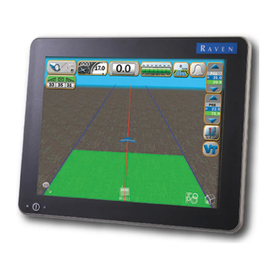
Viper 4 field computer. Orientation The Viper 4 may be mounted in either a portrait or landscape orientation to best suit field operations, operator needs, and implement cabin space. Raven Viper 4 Field Computer with Raven OS FIGURE 1. -
Page 23: Dgps Antenna Mounting Recommendations
The following recommendations are provided to assist with mounting an aerial antenna for use with the Viper 4 integrated receiver. These instructions are not intended to replace instructions provided with any external DGPS equipment. Please refer to and follow all mounting and installation instructions for optional or additional DGPS components provided from the equipment manufacturer. - Page 24 Chapter 4 Viper 4™ Installation Manual...
-
Page 25: Viper 4 System Connections
V iper 4 System CHAPTER C h a p t e r 5 Connections Connecting the Field Computer Best Practices • Use dielectric grease on any connections outside the vehicle cabin to help protect connectors exposed to moisture, chemicals, and the outside environment from dirt, debris, and liquid. •... - Page 26 Chapter 5 Viper 4 Cable Connections (D/N 054-5010-010) FIGURE 1. *Kit Suffix Indicates Included Options. Refer to Figure 1 on page 14. Antenna Cable Viper 4 MBA-6 Antenna Aerial Antenna *Mounting Kit Included Mounting Plate (Not Shown) *Viper 4 Chassis Interface or...
-
Page 27: Viper 4 Adapter Cable
A field computer utilizing an external DGPS receiver will require an console cable with the “DGPS” connector. Install the console or adapter cable as described in the Viper 4 Console Cable section on page 23 or the Viper 4 Adapter Cable section on page 23. -
Page 28: Optional Connections
An ethernet adapter cable is required for the Turck receptacle labeled “3” to connect the Viper 4 to a Slingshot Field Hub to receive RTK corrections. Refer to Figure 3 on page 7. The adapter cable may also be used to connect the Viper 4 with an ethernet enabled device such as a wireless modem. - Page 29 Bring the defective part and proof of purchase to your Raven dealer. If the dealer approves the warranty claim, the dealer will process the claim and send it to Raven Industries for final approval. The freight cost to Raven Industries will be the customer’s responsibility. The Return...
- Page 30 How Can I Get Service? Bring the defective part and proof of purchase to your Raven dealer. If the dealer approves the warranty claim, the dealer will process the claim and send it to Raven Industries for final approval.
- Page 32 Sioux Falls, SD 57117-5107 Fax: 605-331-0426 www.ravenprecision.com www.ravenhelp.com Notice: This document and the information provided are the property of Raven Industries, Inc. and may only be used as authorized by Raven Industries, Inc. All rights reserved under copyright laws. ©Raven Industries, Inc. 2013...
Need help?
Do you have a question about the Viper 4 and is the answer not in the manual?
Questions and answers