Table of Contents
Advertisement
P. O. Drawer E / 161 Gatehouse Road / Sanford, Maine 04073 / USA
800-992-2537 / 207-324-8773 / Fax: 207-324-3869 / bakerco@bakerco.com /
bakerco.com
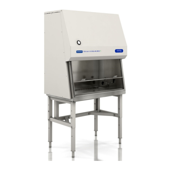
SERVICE MANUAL
Class II, Type A2
Biological Safety Cabinet
MODELS:
SG404 / SG504 / SG604
SG404-INT / SG504-INT / SG604-INT
SG404-JPN / SG504-JPN / SG604-JPN
SG404-AUS / SG604-AUS
M-models are UL listed but not NSF listed
This manual includes information for proper service of this cabinet.
We recommend that it be kept near the cabinet for ready reference.
389D001 Rev G
Advertisement
Table of Contents

Related Manuals for Baker SterilGARD SG604


Summarization of Contents
I - SPECIFICATIONS
Exterior Dimensions
Provides detailed physical measurements for the cabinet models SG404, SG504, and SG604.
Unit Weights
Lists the base and shipping weights for the cabinet in various configurations.
Plumbing Service
Details the standard laboratory air, vacuum, gas, and water service connection requirements.
Electrical Service
Outlines power requirements, circuit protection, and cord specifications for the cabinet.
Exhaust Flow Specifications
Specifies airflow rates (CFM/L/Sec) for different vent configurations and sash openings.
Exhaust Duct Specifications
Provides exhaust duct static pressure ranges for various duct diameters and openings.
Environmental Conditions
Defines the recommended environmental parameters for cabinet operation.
Symbols and Terminology
Explains safety symbols and key terms used in the manual.
II - INSTALLATION
Preparing the SterilGARD®e³ for use
Instructions for unpacking, inspecting the cabinet, and checking parts.
Location within the laboratory
Guidance on selecting the optimal placement for the biosafety cabinet.
Venting into the room
Details on requirements for venting the cabinet exhaust into the laboratory.
Final Connections and Tests
Steps for making final utility connections and performing initial operational tests.
Channel Stand Installation Procedure
Channel Stand Assembly Procedure
Step-by-step instructions for assembling the basic channel stand.
Channel Stand Leg Assembly Procedure
Instructions for assembling adjustable legs to the channel stand.
III - CERTIFICATION
Field Certification Procedures
Overview of procedures for validating cabinet performance by a trained technician.
Cabinet Airflow Verification
Describes methods and tools for verifying cabinet airflow.
HEPA Filter Leak Test Procedure
Protocol for scanning HEPA filters to detect leaks.
Airflow Smoke Pattern Test
Procedure for testing airflow patterns using smoke.
Site Installation Assessment Tests
Tests to assess the quality and safety of the cabinet installation.
IV - MAINTENANCE
HEPA Filter Replacement Procedure
General procedure for replacing HEPA filters, requiring qualified personnel.
Changing the Cabinet Exhaust HEPA Filter
Detailed steps for removing and installing the exhaust HEPA filter.
Changing the Cabinet Supply HEPA Filter
Detailed steps for removing and installing the supply HEPA filter.
View screen Removal Procedure
Instructions for safely removing the front view screen.
Fluorescent Lamp Replacement
Step-by-step guide for replacing the fluorescent lamp.
Ultraviolet Lamp Replacement
Procedure for replacing the UV germicidal lamp.
Touchpad Replacement
Instructions for replacing the cabinet's touchpad control.
Cabinet Pressure Monitor (Optional)
Information on the optional cabinet pressure monitoring system.
Replacement Parts List
A comprehensive list of electrical and mechanical replacement parts.
Ladder Schematics
Electrical ladder diagrams illustrating the cabinet's wiring.
Electrical Panel Assemblies
Diagrams showing the layout and components of electrical panels.
Unit Wiring
General instructions and diagrams for wiring the unit components.
Auxiliary Blower Switch Status Wiring Option
Wiring instructions for the optional blower switch status monitoring.
Auxiliary Cabinet Monitoring Wiring Option
Wiring instructions for the optional cabinet monitoring system.
FlexAIR Canopy Exhaust Connection Wiring
Wiring diagram for the FlexAIR canopy exhaust connection.
Need help?
Do you have a question about the SterilGARD SG604 and is the answer not in the manual?
Questions and answers