
Related Manuals for Eaton W-VAC Series


Summary of Contents for Eaton W-VAC Series
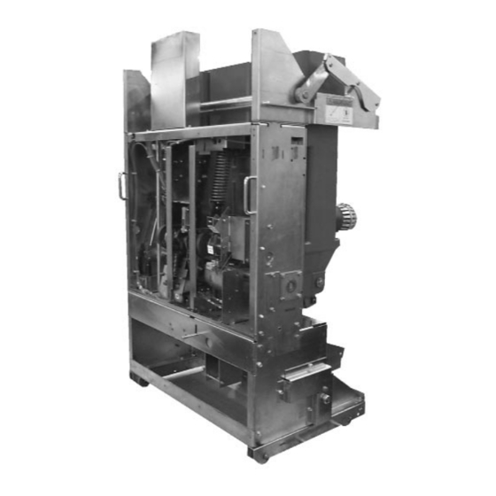
- Page 1 W-VAC 3150A Breaker with Carriage W-VAC Breaker Element Assembly for Single Tier Switchgear W-VAC Breaker with Carriage W-VAC Breaker with Cradle Assembly for Single Tier Switchgear Assembly for Double Tier Switchgear IB131009EN...
- Page 3 All possible contingencies which may arise during installation, operation or maintenance, and all details and variations of this equipment do not purport to be covered by these instructions. If further information is desired by purchaser regarding his particular installation, operation or maintenance of particular equipment, contact an Eaton representative. IB131009EN ...
-
Page 4: Table Of Contents
Instruction Book Page 4 TABLE OF CONTENTS PAGE SECTION 1 INTRODUCTION Type W-VAC, W-VACR and W-VACW Breaker Ratings ..................1 SECTION 2 SAFE PRACTICES SECTION 3 RECEIVING, HANDLING AND STORAGE Receiving ................................14 Handling ................................15 Storage .................................. 15 SECTION 4 INSTALLATION Initial Inspection and Operation .......................... - Page 5 Instruction Book Page 5 5-5 Miscellaneous ................................ 36 5-5.1 Earthing Contact ..............................36 5-5.2 Operations Counter ............................... 36 5-6 Levering Mechanism .............................. 36 5-7 Circuit Breaker Interfacing ............................. 36 5-7.1 Electrical Clearances ............................. 36 SECTION 6 INSPECTION AND MAINTENANCE 6-1 Warning ..................................
- Page 6 Instruction Book Page 6 Type W-VAC Breaker Manual Operation (Single Tier Breaker Shown) ..........23 Flush Mounted Configuration........................26 Behind the Door Configuration ........................27 Closeup of Type W-VAC Breaker Vacuum Interrupters and Current Carrying System ......27 5-4 a Type W-VAC 95 kV BIL Breaker Shown With Left Hand Cover Removed for Clarity Purposes .....
- Page 7 Instruction Book Page 1 SECTION 1: INTRODUCTION WARNING The purpose of this book is to provide instructions for unpacking, storage, installation, operation and mainte- SATISFACTORY PERFORMANCE OF THESE nance of Types W-VAC, W-VACR, and W-VACW BREAKERS IS CONTINGENT UP-ON PROPER Vacuum Circuit Breakers.
- Page 8 Instruction Book Page 2 Table 1.2 Type W-VACR Vacuum Circuit Breaker Ratings Frequency Rated Insulation Level Rated Nominal Current Circuit Rated Rated Short Circuit Breaker Voltage Breaking Current Lighting Power Short Pulse Frequency Circuit Type & Short Circuit Withstand Withstand Making 50-60HZ...
-
Page 9: Type W-Vacr 630A Breaker Element Only Outline Dimensions (Millimeters) & Weights (Kilograms)
Instruction Book Page 3 630A Element 630A = 105kg Figure 1-1 Type W-VACR 630A. breaker element only outline dimensions (millimeters) and weights (kilograms). IB131009EN ... -
Page 10: Type W-Vacr 630A Breaker Element Only Outline Dimensions (Millimeters) & Weights (Kilograms)
Instruction Book Page 4 630A Element 630A = 105kg Figure 1-2 Type W-VACR 630A. breaker element only outline dimensions (millimeters) and weights (kilograms). IB131009EN... -
Page 11: Type W-Vacr 800/1250A Breaker Element Only Outline Dimensions (Millimeters) & Weights (Kg)
Instruction Book Page 5 800/1250A Element 800A/1250A = 110kg Figure 1-3 Type W-VACR 800/1250A. breaker element only outline dimensions (millimeters) and weights (kilograms). IB131009EN ... -
Page 12: Type W-Vacr 800/1250A Breaker Element Only Outline Dimensions (Millimeters) & Weights (Kg)
Instruction Book Page 6 800/1250A Element 800A/1250A = 110kg Figure 1-4 Type W-VACR 800/1250A. breaker element only outline dimensions (millimeters) and weights (kilograms). IB131009EN... -
Page 13: Type W-Vacr 800/1250A Breaker Element Only Outline Dimensions (Millimeters) & Weights (Kg)
Instruction Book Page 7 2000A Element 2000A = 149kg Figure 1-5 Type W-VACR 2000A. breaker element only outline dimensions (millimeters) and weights (kilograms). IB131009EN ... -
Page 14: Type W-Vacr 2000A Breaker Element Only Outline Dimensions (Millimeters) & Weights (Kg)
Instruction Book Page 8 2000A Element 2000A = 149kg Figure 1-6 Type W-VACR 2000A. breaker element only outline dimensions (millimeters) and weights (kilograms). IB131009EN... -
Page 15: Type W-Vacr 2500A Breaker Element Only Outline Dimensions (Millimeters) & Weights (Kg)
Instruction Book Page 9 2500A Element 2500A = 154kg Figure 1-7 Type W-VACR up to 2500A, 50kA. breaker element only outline dimensions (millimeters) and weights (kg.). IB131009EN ... -
Page 16: Type W-Vac Breaker Element Only Outline Dimensions (Millimeters) And Weights (Kilograms)
Instruction Book Page 10 Up to 1250A Element 630A = 115kg 800A/1250A = 121kg (Front View) (Side View) 1600A & 2000A Elements (Side View) (Front View) 1600A/2000A = 160kg Figure 1-8 Type W-VAC breaker element only outline dimensions (millimeters) and weights (kilograms). ... -
Page 17: Outline And Dimensions (Mm) Type W-Vac Breaker Element With Carriage Assembly And Cradle Assembly
Instruction Book Page 11 33.3 “C” POLE “A” POLE “B” POLE 19.34 Earthing Contacts Rating Weight Carriage Up to 15 kV/Up to 1250A to 40kA 1226 1202 1340 Up to 15 kV/1600A and2000A/Up to 40 kA 1299 1275 1340 33.3 “C”... -
Page 18: Outline And Dimensions (Mm) Type W-Vac 3150 Breaker With Carriage Assembly
Instruction Book Page 12 Figure 1-10 Outline and Dimensions (mm) Type W-VAC 3150 breaker with carriage assembly IB131009EN... -
Page 19: Section 2 Safe Practices
Instruction Book Page 13 SECTION 2: SAFE PRACTICES • Do not work on a breaker with the secondary test cou- pler engaged or fixed secondary connections made. Failure to disconnect the test coupler could result in an W-VAC, W-VACR, and W-VACW breakers are electrical shock leading to death, personal injury or equipped with high speed, high energy operating mech- property damage. -
Page 20: Section 3 Receiving, Handling And Storage
Accessories, such immediately with the carrier if damage or loss is detect- as the maintenance tool and levering crank are shipped ed and notify the nearest Eaton Sales Office. separately. Tools and Accessories 3-1 RECEIVING Maintenance Tool: Used to charge the closing springs. -
Page 21: Handling
Instruction Book Page 15 3-3 STORAGE 3-2 HANDING If the circuit breaker is to be placed in storage, maxi- mum protection can be obtained by keeping it in the WARNING original container. DO NOT USE ANY LIFTING DEVICE AS A PLAT- Before placing it in storage, checks should be made to FORM FOR PERFORMING MAINTENANCE, REPAIR make sure that the breaker is free from shipping dam-... -
Page 22: Typical Front View Vcp-W Vacuum Circuit Breaker Element
Instruction Book Page 16 ➀ ➄ Front Panel Operation Counter ➁ ➅ Manual Charge Socket Rating Nameplate ➂ ➆ Open-Closed Indicator Manual Open Button ➃ ➇ Spring Charged/Discharged Indicator Manual Close Button Figure 3-2 Type W-VAC breaker element faceplate ... -
Page 23: Typical Vcp-W Vacuum Circuit Breaker Element With Front Cover Removed
Instruction Book Page 17 ➀ ➈ L.H. Closing Spring Charging Motor ➁ ➉ Anti-pump Relay Charging Pawl ➂ Auxiliary Switch Ratchet Wheel ➃ Motor Cutoff Switch R.H. Closing Spring ➄ Closing Cam Opening Spring ➅ Spring Release (Close Coil) Assembly Manual Charge Socket ➆... -
Page 24: Typical Rear View Vcp-W Vacuum Circuit Breaker Element
Instruction Book Page 18 ➀ ➅ Secondary Disconnect Contact Loading Spring “Wipe Spring” ➁ ➆ Lifter Yoke Opening Operating Rod ➂ ➇ Support Insulator Drive Insulator ➃ ➈ Primary Disconnect Flexible Connector ➄ Vacuum Interrupter Figure 3-4 Rear external view of W-VAC breaker element ... -
Page 25: Typical Vcp-W Vacuum Circuit Breaker Element Escutcheon
Instruction Book Page 19 Side View Rear View ➀ ➅ Mechanism Enclosure Carriage Wheel ➁ ➆ Support Insulator Shoot Bolt Lever ➂ ➇ Primary Disconnect Shutter Operator ➃ ➈ Levering in Screw Levering Device Socket ➄ Carriage Figure 3-5 Side and rear external view W-VAC breaker with carriage assembly for single tier switchgear IB131009EN ... -
Page 26: Front And Rear External View W-Vac Breaker With Cradle Assembly For Double Tier Switchgear
Instruction Book Page 20 Front View Rear View ➀ ➅ Mechanism Enclosure Cradle Wheel ➁ ➆ Support Insulator Shutter Operator ➂ ➇ Primary Disconnect Levering Device Socket ➃ ➈ Levering in Screw Shoot Bolt Lever ➄ ➉ Cradle Earthing Contact Figure 3-6 Front and rear external view W-VAC breaker with cradle assembly for double tier switchgear ... -
Page 27: Front And Rear External View W-Vac 3150A Breaker With Carriage Assembly For Single Tier Switchgear
Instruction Book Page 21 Front View Rear View ➀ ➅ Mechanism Enclosure Carriage Wheel ➁ ➆ Support Insulator Shoot Bolt Lever ➂ ➇ Primary Disconnect Shutter Operator ➃ ➈ Levering in Screw Levering Device Socket ➄ Carriage Figure 3-7 Front and rear external view W-VAC 3150A breaker with carriage assembly for single tier switchgear IB131009EN ... -
Page 28: Section 4 Installation
Instruction Book Page 22 SECTION 4: INSTALLATION breaker. Check contact erosion and wipe as described in Section 6.5. 4-6 PRIMARY CIRCUIT RESISTANCE Check the primary circuit resistance as described in BEFORE PLACING THE BREAKER IN SERVICE, Section 6.8 The resistance should not exceed the val- CAREFULLY FOLLOW THE INSTALLATION PROCE- ues specified. -
Page 29: Type W-Vac Breaker Manual Operation (Single Tier Breaker Shown)
Instruction Book Page 23 a. Inserting the maintenance tool into b. Lifting shoot lever permits insertion the manual charging socket of levering crank c. Manually closing the breaker d. Manually tripping the breaker Figure 4-1 Type W-VAC breaker manual operation (single tier breaker shown) IB131009EN ... -
Page 30: Breaker/Compartment Interface Check
Instruction Book Page 24 ondary contacts when in the disconnected position. The d) Anti-Latch Interlock: This interlock prevents the structure mounted secondary contact blocks are perma- breaker from being closed between the Connected and nently mounted and cannot be moved out for direct con- Test positions. - Page 31 Instruction Book Page 25 Step 6: Withdraw Breaker from Test Position: 1. For the single tier configuration carriage assembly version, lift the shoot bolt lever and pull the breaker out. The breaker will close and trip as it comes out from the Test position.
-
Page 32: Section 5 Description And Operation
(Figure 5-2). 5-1.1 VACUUM INTERRUPTER W-VAC breakers utilize Eaton vacuum inter- rupters to close and open the primary circuit. The mech- anism is All the circuit breakers utilize vacuum interrupters for a front mounted, spring stored energy type, which is interruption and switching functions. -
Page 33: 5-1.2 Contact Erosion Indicator (Except 3150A)
The purpose of the contact erosion indicator is to moni- tor the erosion of the vacuum interrupter contacts, which is very minimal over time with Eaton vacuum interrupters utilizing copper-chrome contact material. If contact erosion reaches 1/8 inch, the interrupter must be replaced. -
Page 34: 5-1.4 "T" Cutout Loading Spring Indicator
A great deal of effort has been spent in the design of all Eaton vacuum breakers, in order to eliminate the need for field adjustments of wipe or stroke. -
Page 35: Stored Energy Mechanism
Instruction Book Page 29 W-VAC, WVACR, and W-VACW designs utilizes contin- 5-2.2 CHARGING uous glass polyester moldings to support individual pole units. All 95 KV BIL 630 through 1250 ampere rated Figure 5-6 is a schematic view of the spring charging breakers require an additional cover to be added to the parts of the stored energy mechanism. -
Page 36: Closing Cam And Trip Linkage
Instruction Book Page 30 ➉ ➂ ➁ ➆ ➇ ➀ ➃ ➄ ➈ ➅ Figure 5-5a Breaker open and closing spring Figure 5-5b Breaker open and closing spring discharged discharged Figure 5-5c Breaker closed and closing Figure 5-5d Breaker closed and closing spring discharged spring charged ➀... -
Page 37: Charging Schematic
Instruction Book Page 31 ➅ ➄ ➃ ➂ ➇ ➉ ➈ ➀ ➆ Breaker Open, Springs Discharged Breaker Closed, Springs Charged ➀ ➇ Pole Shaft Cam Shaft ➁ ➈ Anti-Close Interlock Motor Ratchet Lever ➂ ➉ Spring Release (Close) Latch Drive Pawl ➃... -
Page 38: 5-2.4 Tripping Operation
Instruction Book Page 32 turn. Since the cam surface in contact with the main link 5-3.1 TIMING roller is cylindrical in this region, the spring charging operation does not affect the mechanism linkage. The opening and closing times for the circuit breakers vary depending upon the control voltage and the power Since the primary contacts are completely enclosed in rating. -
Page 39: 5-3.3 Undervoltage Trip Device
Instruction Book Page 33 5-3.3 UNDERVOLTAGE TRIP DEVICE SEVERE PERSONAL INJURY OR PROPERTY DAM- AGE. The undervoltage trip device for all circuit breakers is an electromechanical device that operates to open the All W-VAC and W-VACW breakers are equipped with breaker at 35% or less of the voltage rating of the trip several interlocks. -
Page 40: Typical Dc And Ac Control Schemes
Instruction Book Page 34 Figure 5-7 Typical DC and AC control schemes IB131009EN... -
Page 41: Undervoltage Trip Device Configuration
Instruction Book Page 35 ➃ ➁ ➀ ➇ ➂ ➁ ➅ ➆ ➈ ➄ ➀ ➄ Moving Clapper Trip D Shaft Lever ➁ ➅ Stationary Yoke Slotted Link ➂ ➆ UV Trip Device Coil Pole Shaft Lever ➃ ➇... -
Page 42: Miscellaneous
ADDITIONS TO THE BREAKER ELEMENTS AS SUP- circuit breakers prior to inserting a drawout circuit break- PLIED BY EATON MUST BE MADE IN KEEPING er into a cell, permanently mounting a fixed circuit WITH APPLICABLE IEC STANDARDS. UNDER NO breaker and/or placing a circuit breaker in service. -
Page 43: Section 6 Inspection And Maintenance
Instruction Book Page 37 SECTION 6: INSPECTION AND FAILURE TO FOLLOW ANY OF THESE INSTRUC- TIONS MAY CAUSE DEATH, SERIOUS BODILY MAINTENANCE INJURY, OR PROPERTY DAMAGE. SEE SECTION 2- SAFE PRACTICES FOR MORE INFORMATION. 6-2 FREQUENCY OF INSPECTION WARNING Inspect the breaker once a year when operating in a clean, non corrosive environment. -
Page 44: Inspection And Maintenance Procedures
Instruction Book Page 38 6-3 INSPECTION AND MAINTENANCE PROCEDURES No./Section Inspection Item Criteria Inspection Method Corrective Action 1. Insulation Drive Insulator No dirt Visual Check Clean with lint-free cloth Molded Pole Unit Support No cracking Visual Check Replace cracked unit Insulation Main Circuit to Ground Withstand... - Page 45 Instruction Book Page 39 No./Section Inspection Item Criteria Inspection Method Corrective Action 4. Operating Dust or Foreign Matter No dust or foreign Visual Check Clean as necessary Mechanism matter Lubrication Smooth operation Sight and feel Lubricate very sparingly and no excessive with light machine oil wear...
-
Page 46: Contact Erosion (Except 3150A)
Instruction Book Page 40 Figure 6-2 Vacuum interrupter showing contact erosion Figure 6-3 Vacuum interrupter showing contact erosion indicator with breaker open (shown here for clarity pur- indicator with breaker closed (indicators are checked poses only). only when breaker is closed). WARNING 6-5.1 CONTACT EROSION (3150A ONLY) In order to determine if the contacts of a 3150 ampere... -
Page 47: Insulation
If a solvent is disconnecting terminals in the two motor leads provided required to cut dirt, use Stoddard's Solvent Eaton for this purpose. Connect all points of the secondary dis- 55812CA or commercial equivalent. -
Page 48: Primary Circuit Resistance Check
Instruction Book Page 42 6-8 PRIMARY CIRCUIT RESISTANCE CHECK Since the main contacts are inside the vacuum cham- ber, they remain clean and require no maintenance at any time. Unlike most typical circuit breaker designs, W- VAC, W-VACR and W-VACW breakers do not have slid- ing contacts at the moving stem either. - Page 49 Step 11 - Push the “push to open” clapper to open the The recommendations and information contained herein circuit breaker. are based on Eaton experience and judgment, but should not be considered to be all-inclusive or cov- Step 12 - Inspect the circuit breaker to assure it is in the ering every application or circumstance which may open position and the closing springs are discharged.
- Page 50 Instruction Book Page 44 Figure 6-11 Attaching Tape Around to Back of Cam Figure 6-8 Status Indicators (“A” shows the contact status indication and “B” shows the spring indication.) Figure 6-12 Attaching CloSure Test Tool at Hole “A” Figure 6-9 Starting Tape at Bottom of Cam Figure 6-13 Attaching CloSure Test Tool at Hole “B”...
- Page 51 Instruction Book Page 45 Figure 6-14 Manually Charging Closing Springs Figure 6-17 Move Marker 15 to Right Figure 6-15 Manually Closing Circuit Breaker with Marker in Hole “C”. Figure 6-18 Move Marker 15 to Left Closure Tool Marker Figure 6-19 Remove Marked Masking Tape from Cam Figure 6-16 Top View of Cam and Marker Interface IB131009EN...
- Page 52 Instruction Book Page 46 Width Figure 6-20 Place Tape on Right Side Panel of Breaker * Figure not to scale * Note: Use the center of the marker diameter to determine “X” distance Figure 6-23 Typical Circuit Breaker Front View with CloSure Tool Attached (approximate mechanism chassis width)
-
Page 53: Lubrication
Eaton No. 53701QB. Over a period of time, this many years. They should not be disturbed unless there lubricant may be pushed out of the way or degrade. - Page 54 Instruction Book Page 48 SYMPTOM INSPECTION AREA CONTROL DEFECTS Fails To Close • No Closing Sound • Control Power • Closing Springs charged but breaker does not close (Close Coil does not pick up) (Fuse Blown or switch off) •...
- Page 55 Instruction Book Page 49 SYMPTOM INSPECTION AREA CONTROL DEFECTS Fails to Trip • Control Power • No Trip Sound • Control Circuit (Fuse blown or switch off) • Secondary Disconnect • Auxiliary Switch (a contact no making, poor or burned) •...
-
Page 56: Section 7 Renewal Parts
Specify the method of shipping desired. own stock level based on operating experience. Refer to Table 7.1 for guidance. e.) Send all orders or correspondence to the nearest Eaton sales office. Table 7.1 Recommended W-VAC, W-VACR and W-VACW Spare Parts Line No. - Page 57 Instruction Book Page 51 Line No. Description Style W-VACR Pole Unit Assy, 1250A, 4D13307G13 Up to 15 kV, 31.5 kA, 95 kV BIL W-VACR Pole Unit Assy, Up to 2500A, 4D13307G65 15 kV, 50 kA, 95 kV BIL ...
- Page 58 Instruction Book Page 52 Line No. Description Style W-VAC Pole Unit Assy, 2000A, 4D13307G04 Up to 15 kV, 31.5 kA and 95 kV BIL W-VAC Pole Unit Assy, 630A, 4D13307G06 Up to 17.5 kV, 25kA, 95 kV BIL (Plus) Cover 4D13343H01 W-VAC Pole Unit Assy, 1250A, 4D13307G07...
- Page 59 Instruction Book Page 53 Line No. Description Style W-VACW Pole Unit Assy (continued from previous page) (continued from previous page) 12 kV, 1250A, 31.5kA 69D3313H16 12 kV, 1600A, 31.5kA 69D3313H25 12 kV, 2000A, 31.5kA 69D3313H29 12 kV, 1250A, 40kA 69D3313H17 12 kV, 2000A, 40kA 69D3313H30...
- Page 60 Instruction Book Page 54 Effective: October 2005 Line No. Description Style Shunt Trip Coils 48 VDC 3759A76G01 110-125 VDC/110-125 VAC Cap trip 3759A76G02 220-250 VDC/220-250 VAC Cap trip 3759A76G03 UV Trip Coils 48 VDC 8064A19G01 110/125 VDC 8064A19G02 220/250 VDC 8064A19G03...
- Page 61 ...
- Page 62 Instructions for Installation, Operation and Maintenance of Instruction Book Types W‐VAC, W‐VACR, and W‐VACW Vacuum Circuit Breakers ...
Need help?
Do you have a question about the W-VAC Series and is the answer not in the manual?
Questions and answers