Table of Contents
Advertisement
Quick Links
Residual Current Devices
Residual Current Devices - General Data
Short description of the most important RCD types:
Symbol
G
ÖVE E 8601
S
"röntgenfest"
"umrichterfest"
Description
Eaton standard. Suitable for outdoor installation (distribution boxes for outdoor installation and
building sites) up to -25° C.
Conditionally surge-current proof (>250 A, 8/20 µs) for general application.
RCD sensitive to pulsating DC for application where residual pulsating DC may occur. Non-selec-
tive, instantaneous. Protects only against special forms of residual pulsating DC which have not
been smoothed.
Type B: All-current sensitive RCD switchgear for applications where DC fault currents may occur.
Non-selective, non-delayed. Protection against all kinds of fault currents.
Type B+: All-current sensitive RCD switchgear for applications where DC fault currents may occur.
Non-selective, non-delayed. Protection against all kinds of fault currents. Also meets the require-
ments of the VDE 0664-400 standard (formerly known as VDE V 0664-110) and therefore provides
enhanced fire safety.
RCD of type G (min 10 ms time delay) surge current-proof up to 3 kA. For system components
where protection against unwanted tripping is compulsory to avoid personal injury and damage to
property (§ 12.1.6 of ÖVE/ÖNORM E 8001-1). Also for systems involving long lines and high line
capacity. Some versions are sensitive to pulsating DC. Some versions are available in all-current
sensitive design.
RCD of type S (selective, min 40 ms time delay) surge current-proof up to 5 kA. Mainly used as
main switch according to ÖVE/ÖNORM E 8001-1 § 12.1.5, as well as in combination with surge
arresters.This is the only RCD suitable for series connection with other types if the rated tripping
current of the downstream RCD does not exceed one third of the rated tripping current of the
device of type S. Some versions are sensitive to pulsating DC. Some versions are available in all-
current sensitive design.
"X-ray-proof", for avoiding unwanted tripping caused by x-ray devices.
"Frequency converter-proof", for avoiding unwanted tripping caused by frequency converters,
speed-controlled drives, etc.
Chapter 2.1.1. – 1
EATON CORPORATION xxxxx+xxxx-xxxxEN
Advertisement
Table of Contents

Related Manuals for Eaton xEffect


Summary of Contents for Eaton xEffect
- Page 1 Short description of the most important RCD types: Symbol Description Eaton standard. Suitable for outdoor installation (distribution boxes for outdoor installation and building sites) up to -25° C. Conditionally surge-current proof (>250 A, 8/20 µs) for general application. RCD sensitive to pulsating DC for application where residual pulsating DC may occur. Non-selec- tive, instantaneous.
- Page 2 Tripping time range limit values time range specified by the manufacturer of the measuring instru- Tripping time range non-delayed Tripping time range type S ment. Area of unwanted tripping Tripping time range type G EATON CORPORATION xxxxx+xxxx-xxxxEN Chapter 2.1.1. – 2...
-
Page 3: Protective Measures
50 V AC or 120 V DC is not exceeded. (In ÖVE/ÖNORM E 8001-1 the term "touch voltage" has been omitted. There is only a fault voltage limit of 65 V AC or 120 V DC which must not be exceeded). EATON CORPORATION xxxxx+xxxx-xxxxEN Chapter 2.1.1. – 3... - Page 4 • New level of accuracy -> reduced unwanted tripping • No monthly test required • Comprehensive range of accessories • Real contact position indicator • Fault current tripping indicator • Automatic re-setting possible • Transparent designation plate EATON CORPORATION xxxxx+xxxx-xxxxEN Chapter 2.2.1. – 1...
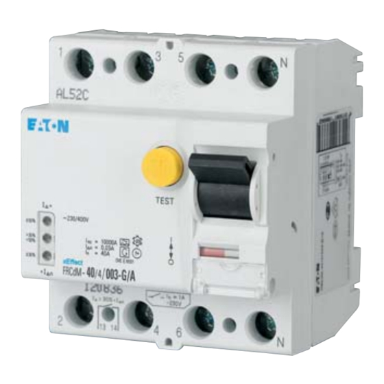
- Page 5 4-pole SG49712 40/0.03 *) FRCdM-40/4/003-U 168643 1/30 40/0.3 FRCdM-40/4/03-U 168644 1/30 63/0.03 *) FRCdM-63/4/003-U 168640 1/30 63/0.3 FRCdM-63/4/03-U 168641 1/30 80/0.3 FRCdM-80/4/03-U 168642 1/30 *) Short time delayed + surge current-proof 3 kA EATON CORPORATION xxxxx+xxxx-xxxxEN Chapter 2.2.1. – 2...
- Page 6 • Shape compatible with and suitable for standard busbar connec- - The green LED becomes active at 0-30% I Δn tion to other devices of the xEffect-series - The yellow LED becomes active at 30-50% I Δn • Twin-purpose terminal (lift/open-mouthed) above and below - The red LED becomes active at >50% I...
-
Page 7: Technical Data
-25°C to +40°C Storage- and transport temperature -35°C to +60°C Resistance to climatic conditions 25-55°C/90-95% relative humidity acc. to IEC 60068-2 Contact position indicator red / green Tripping indicator white / blue Connection diagram 4-pole EATON CORPORATION xxxxx+xxxx-xxxxEN Chapter 2.2.1. – 4... -
Page 8: Remote Indication
1+N (240V) (415V AC Phase-Phase) (240/415V) (240V AC AC Phase-Phase) Electronic works within 50-264V AC ! - Disconnect load side of the switch gear, if you make a insulation test of the installation! EATON CORPORATION xxxxx+xxxx-xxxxEN Chapter 2.2.1. – 5... - Page 9 • New level of accuracy -> reduced unwanted tripping • No monthly test required • Comprehensive range of accessories • Real contact position indicator • Fault current tripping indicator • Automatic re-setting possible • Transparent designation plate EATON CORPORATION xxxxx+xxxx-xxxxEN Chapter 2.2.1. – 6...
- Page 10 Residual Current Devices FRCdM Typ S/B+ Selective + surge current-proof 5 kA, type S/B+ Type Article No. Units Δn Designation package 4-pole SG49812 25/0.3 FRCdM-25/4/03-S/B+ 167888 1/30 40/0.3 FRCdM-40/4/03-S/B+ 167889 1/30 63/0.3 FRCdM-63/4/03-S/B+ 167890 1/30 EATON CORPORATION xxxxx+xxxx-xxxxEN Chapter 2.2.1. – 7...
- Page 11 Residual Current Devices FRCdM Typ S/Bfq Selective + surge current-proof 5 kA, type S/Bfq Type Article No. Units Δn Designation package 4-pole SG49812 25/0.3 FRCdM-25/4/03-S/Bfq 167908 1/30 40/0.3 FRCdM-40/4/03-S/Bfq 167909 1/30 63/0.3 FRCdM-63/4/03-S/Bfq 167910 1/30 EATON CORPORATION xxxxx+xxxx-xxxxEN Chapter 2.2.1. – 8...
- Page 12 • Shape compatible with and suitable for standard busbar connec- - The green LED becomes active at 0-30% I Δn tion to other devices of the xEffect-series - The yellow LED becomes active at 30-50% I Δn • Twin-purpose terminal (lift/open-mouthed) above and below - The red LED becomes active at >50% I...
- Page 13 Storage- and transport temperature -35°C to +60°C Resistance to climatic conditions 25-55°C/90-95% relative humidity acc. to IEC 60068-2 Contact position indicator red / green Tripping indicator white / blue Connection diagram 4-pole Netz Mains Last Load EATON CORPORATION xxxxx+xxxx-xxxxEN Chapter 2.2.1. – 10...
- Page 14 Test button works within 184-264V (30mA) bzw. 184-440V (300mA)! - Disconnect load side of the switch gear, if you make a insulation test of the installation! - Please take care of supply side and load side! EATON CORPORATION xxxxx+xxxx-xxxxEN Chapter 2.2.1. – 11...
Need help?
Do you have a question about the xEffect and is the answer not in the manual?
Questions and answers