TERSUS David User Manual
Hide thumbs
Also See for David:
- User manual (76 pages) ,
- Quick start manual (2 pages) ,
- Quick start manual (13 pages)
Table of Contents

Related Manuals for TERSUS David


Summary of Contents for TERSUS David
-
Page 1: User Manual
User Manual Version V2.1-20190419 User Manual For David GNSS Receiver ©2019 Tersus GNSS Inc. All rights reserved. Sales & Technical Support: sales@tersus-gnss.com & support@tersus-gnss.com More details, please visit www.tersus-gnss.com... -
Page 2: Revision History
User Manual for David GNSS Receiver v2.1 Revision History Version Revision Date Change summary 20180702 Initial Release 20190131 Chapter 2: removed rover kit with 1W radio and base kit with 1W radio, update device names; Chapter 3: section 3.4 firmware update;... -
Page 3: Table Of Contents
User Manual for David GNSS Receiver v2.1 Table of Content Revision History........................1 Table of Content........................2 List of Figures........................... 5 List of Tables..........................9 Notices..……………………………………………………………………………………..10 Overview........................12 Introduction......................12 Receiver Features....................13 Brief Introduction of GNSS and RTK..............13 Devices in David Package..................16 Rover Kit Network Mode.................. - Page 4 User Manual for David GNSS Receiver v2.1 2.2.4 TNC-J to TNC-J Cable 1.0m (Radio Antenna Extension Cable).... 31 2.2.5 Bracket for 460M antenna with TNC-TNC converter........ 32 Base Kit Network Mode..................32 2.3.1 Bracket for Base..................... 34 2.3.2 Tape Measure....................34 2.3.3...
- Page 5 2W Radio RS400L2....................72 30W Radio RS400L30...................75 Typical operation....................78 David as a Rover to receive corrections from Internet........79 David as a Base to transmit corrections to Internet.......... 82 Radios Transmit RTK Corrections between Two David receivers....85 Data Collection for Post Processing..............89 Auto Base Station List Function................92...
-
Page 6: List Of Figures
User Manual for David GNSS Receiver v2.1 List of Figures Figure 1.1 Outlook of David GNSS receiver.............12 Figure 1.2 Outline of David System................14 Figure 1.3 Corrections transmitted via Internet............14 Figure 1.4 Corrections transmitted with radios............15 Figure 2.1 Devices in the box..................16 Figure 2.2 Rover Kit Network Mode................17... - Page 7 Figure 2.34 Telescopic pole for radio antenna............39 Figure 2.35 Hook and Screws for 2W Radio (attached to 2W radio)....40 Figure 2.36 Hook and Screws for David (attached to David)........ 40 Figure 2.37 Bracket for Mobile..................41 Figure 2.38 Toolbag...................... 41 Figure 2.39 Base Kit with 30W Radio................42...
- Page 8 Figure 5.1 Panel of David.................... 70 Figure 5.2 Pin Definition of the COMM1/COMM2/DC ports........70 Figure 6.1 Outline of Android phone to David with Wire – Rover......79 Figure 6.2 Connect David via USB................80 Figure 6.3 Rover setting interface................81 Figure 6.4 Edit Rover configuration................
- Page 9 User Manual for David GNSS Receiver v2.1 Figure 6.11 Outline of Base/Rover with Radios............85 Figure 6.12 Base work mode list................87 Figure 6.13 Edit base configuration................87 Figure 6.14 Rover work mode list................88 Figure 6.15 Edit rover configuration................88 Figure 6.16 Outline of Static Data Collection............
-
Page 10: List Of Tables
Table 10 Definition of the Control Buttons..............44 Table 11 Definition of LEDs..................44 Table 12 David GNSS Performance................68 Table 13 Pin Definition of connectors on David............70 Table 14 Antenna AX3702................... 71 Table 15 Specifications of 2W Radio RS400L2............72 Table 16 Default factory configuration for RS400L2..........74... -
Page 11: Notices
A warning that actions, operations or configurations may result in regulatory noncompliance, safety issues or equipment damage. NUWA is Tersus survey app, four tabs (Project, Device, Survey and Tools) are provided in the Nuwa main interface. All the operations in the Survey software start from these four tabs. - Page 12 Tersus Geomatics Post processing tool for static data https://www.tersus-gnss.com/software/ Office david-receiver Support If there is any problem and the information needed cannot be found in the product documentation, request technical support using the Tersus website at www.tersus-gnss.com, or mail to support@tersus-gnss.com...
-
Page 13: Overview
Tersus DAVID is a cost-efficient, palm-sized GNSS receiver, mainly for the mass survey market, and also for UAV / AGV / Agriculture application. Nuwa, a survey App on Android system, works with David for the survey. And David receiver can communicate with an Android platform such as a phone or tablet via USB cable or an external Bluetooth module. -
Page 14: Receiver Features
Brief Introduction of GNSS and RTK Tersus BX306 GNSS receiver is integrated in David, the board is receiving the GNSS signals from satellites and RTK corrections from the base, and is outputting cm-level position, velocity and time. Figure 1.2 shows the outline of David system;... -
Page 15: Figure 1.2 Outline Of David System
Figure 1.2 Outline of David System The RTK corrections are transmitted from a base, which can be a CORS station or a David receiver. The RTK corrections can be transmitted to the rover via Internet or with external radios. Figure 1.3 Corrections transmitted via Internet... -
Page 16: Figure 1.4 Corrections Transmitted With Radios
User Manual for David GNSS Receiver v2.1 Figure 1.4 Corrections transmitted with radios If RTK corrections are transmitted via Internet, an Android phone or controller will be included in the RTK system to transmit/receive the RTK corrections, refer to section 6.1 and section 6.2 for detailed operations. -
Page 17: Devices In David Package
2. Devices in David Package This chapter is to give detailed introduction about all the devices in the package. David has five variants, which are convenient for customers to select according to their application. Different accessories are included in each variant. -
Page 18: Rover Kit Network Mode
Base Kit with 30W Radio Station. Rover Kit Network Mode In this variant, the David is connected to an Android phone or controller with Bluetooth module or with cables. Tersus Survey Nuwa App is installed and run in the Android phone or controller to receive RTK corrections from a NTRIP caster or a TCP server. -
Page 19: Figure 2.18 Power Bank
User Manual for David GNSS Receiver v2.1 Table 3 Devices in Rover Network Mode Device Name Quantity Items in Figure 2.2 AX3702 GNSS antenna Ranging pole TC20 Controller 3, not included in the package COMM1-Bluetooth module 4, refer to section 2.1.4 DC-2pin to USB power cable 5, refer to Figure 2.7... -
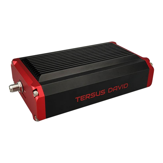
Page 20: David Gnss Receiver
DC port Figure 2.3 David GNSS Receiver The DC port of David is for power input, COMM1 port is for COM1 and CAN ports, and COMM2 port is for COM2 and USB ports, refer to chapter 5 for detailed specification. -
Page 21: Ax3702 Gnss Antenna
User Manual for David GNSS Receiver v2.1 2.1.2 AX3702 GNSS Antenna AX3702 GNSS antenna is used to receive the RF signal from the satellites, and it must be connected to the David with the GNSS antenna cable in the package. Figure 2.4 AX3702 GNSS Antenna If an antenna from other companies is used, contact Tersus to obtain permission, or the David receiver may not work as expected. -
Page 22: Dc-2Pin To Usb Power Cable
User Manual for David GNSS Receiver v2.1 Figure 2.6 GNSS Antenna Connector 2.1.3 DC-2pin to USB Power Cable The power cable is used to connect a power bank to the DC port of David receiver. Figure 2.7 DC-2pin to USB Power Cable 2.1.4 COMM1-Bluetooth Module... -
Page 23: Comm2-7Pin To Usb & Db9 Cable
Download Files from Internal EMMC Card; 2. Connect to USB Type A Female to USB (Micro +Type C) OTG cable (refer to Figure 2.11) to connect the Android phone or controller with David, refer to section 3.3.1. Figure 2.9 COMM2-7pin to USB & DB9 Cable The COMM2-7pin to USB &... -
Page 24: Db9 Male To Usb Type A Male Converter Cable
User Manual for David GNSS Receiver v2.1 2.1.6 DB9 Male to USB Type A Male converter cable DB9 Male to USB Type A Male converter cable to connect with the COMM2-7pin to USB & DB9 Cable in Figure 2.9 of section 2.1.5. -
Page 25: Height Measure Accessory
User Manual for David GNSS Receiver v2.1 2.1.8 Height Measure Accessory The height measure accessory is used to determine the height of the antenna with higher accuracy. Figure 2.12 Height Measure Accessory 2.1.9 Wrench The wrench is used to reinforce the SMA Cable (GNSS antenna cable) to the SMA connector of David receiver. -
Page 26: Figure 2.14 Bracket For Rover
User Manual for David GNSS Receiver v2.1 Figure 2.14 Bracket for Rover Figure 2.15 Ranging Pole Figure 2.16 Magic Tape A yellow carrying case marked with GNSS ROVER is to store all the devices and accessories of rover kit. -
Page 27: Figure 2.17 Carrying Case For Rover
User Manual for David GNSS Receiver v2.1 Figure 2.17 Carrying Case for Rover A power bank is used to power on the David, it is not included in the package, and is to be prepared by the customers, refer to section Power on David for more details. -
Page 28: Rover Kit With 2W Radio Station
User Manual for David GNSS Receiver v2.1 Rover Kit with 2W Radio Station In this variant, the David receiver is connected to an external 2W radio to receive RTK corrections from a base. With an external Bluetooth or cables, the David receiver is connected to an Android phone or controller, which runs Tersus Survey software Nuwa to configure the David GNSS receiver. -
Page 29: Table 6 Rover Kit With 2W Radio Station
User Manual for David GNSS Receiver v2.1 The power bank and controller are not included in the package. The TC20 controller is listed on https://www.tersus-gnss.com/product/tc20-controller Table 6 Rover Kit with 2W Radio Station Device Name Quantity Items in field photos 2W/460MHz radio antenna 1, refer to Figure 2.23... -
Page 30: 460Mhz Radio
User Manual for David GNSS Receiver v2.1 Not in the figure above, refer to Figure Height measure accessory 2.12. Not in the figure above, refer to section GNSS antenna connector 2.1.2 for detail. Not in the figure above, refer to section COMM2-7pin to USB &... -
Page 31: 460Mhz Radio Antenna
Press once to select the output power, which can be 1W or 2W. Button Press protocol button to switch the protocols between TP Protocol (Transparent EOT protocol) , TT (TT450S protocol) and TS (Tersus Button protocol) Two 2W radios must have the same protocol and the same channel frequency before they can communicate each other. -
Page 32: Comm2-7Pin To Usb & 2W-Radio-5Pin Cable
2.2.3 COMM2-7pin to USB & 2W-Radio-5pin Cable The COMM2-7pin to USB & 2W-Radio-5pin Cable is used to connect the David receiver to the 2W radio station & an Android phone. The length of the cable is 0.55m. Figure 2.22 COMM2-7pin-USB & 2W-Radio-5pin Cable COMM2-7pin to USB &... -
Page 33: Bracket For 460M Antenna With Tnc-Tnc Converter
Figure 2.24 Bracket for 460M antenna with TNC – TNC converter Base Kit Network Mode In this variant, the David, working as a base, transmits RTK corrections to a NTRIP caster or a TCP sever. The David is connected to an Android phone with an external Bluetooth or with cables. -
Page 34: Figure 2.25 Base Kit Network Mode
Items in field photo AX3702 GNSS antenna GNSS antenna connector TC20 Controller COMM1-Bluetooth module 4, refer to 2.1.4 DC-2pin to USB power cable Bracket for base 6, refer to Figure 2.26 Power bank 7, refer to Figure 2.18 and Power on David... -
Page 35: Bracket For Base
2.3.1 Bracket for Base This bracket is hooked on the tripod and all the devices in the field (an Android phone, a radio, a David and a power bank) are installed on it, which brings much convenience for field job. -
Page 36: Other Accessories
Figure 2.28 Carrying Case for Base Base Kit with 2W Radio Station In this variant, the David, working as a base, transmits RTK corrections to an external 2W radio. The David is connected to an Android phone with cables or with the Bluetooth module. -
Page 37: Figure 2.29 Base Kit With 2W Radio
User Manual for David GNSS Receiver v2.1 The descriptions of basic components for this kit refer to section 2.1. This section introduces different devices required for Base Kit with 2W Radio Station. Base Kit with 2W Radio Station can work with Rover Kit with 2W Radio Station only. - Page 38 User Manual for David GNSS Receiver v2.1 Table 10 Base Kit with 2W Radio Station Device Name Quantity Items in field photo AX3702 GNSS antenna 1, refer to section 2.1.2 GNSS antenna connector 2, refer to section 2.1.2 2W/460MHz radio 3, refer to section 2.2.1...
-
Page 39: Dc-2Pin To Bullet-Dc Power Cable
User Manual for David GNSS Receiver v2.1 2.4.1 DC-2pin to Bullet-DC Power cable The DC-2pin of this cable is to connect to the DC port of David receiver, the Bullet-DC is to connect with Bullet-DC to Alligator Clips in the figure below. -
Page 40: Metal Plate For Radio Antenna
User Manual for David GNSS Receiver v2.1 Figure 2.32 High Gain Radio Antenna 2.4.4 Metal plate for radio antenna This metal plate is used to fixate the radio antenna to the tripod. Figure 2.33 Metal plate for radio antenna 2.4.5 Telescopic pole for radio antenna The telescopic pole is used to extend the height for radio antenna. -
Page 41: Hook And Screws For 2W Radio
Figure 2.35 Hook and Screws for 2W Radio (attached to 2W radio) 2.4.7 Hook and Screws for David The hook and screws below are attached to David receiver for hanging on the tripod. Figure 2.36 Hook and Screws for David (attached to David) 2.4.8 Bracket for Mobile... -
Page 42: Other Accessories
Figure 2.38 Tool bag Base Kit with 30W Radio Station In this variant, the David, working as a base, transmits RTK corrections to an external 30W radio. The David is connected to an Android phone with cables or with the Bluetooth module. Tersus Survey Nuwa app is installed in the Android phone to configure the David. -
Page 43: Figure 2.39 Base Kit With 30W Radio
User Manual for David GNSS Receiver v2.1 This section introduces different devices required for Base Kit with 30W Radio Station. Base Kit with 30W Radio Station can work with Rover Kit with 2W Radio Station only. Base Kit with 30W Radio Station can support Base network mode. -
Page 44: Table 9 Base Kit With 30W Radio Station
User Manual for David GNSS Receiver v2.1 Table 9 Base Kit with 30W Radio Station Device Name Quantity Items in field photos AX3702 GNSS antenna 1, refer to section 2.1.2 GNSS antenna connector 2, refer to section 2.1.2 GNSS antenna cable 3, refer to section 2.1.2... -
Page 45: Radio
User Manual for David GNSS Receiver v2.1 2.3.1 30W Radio The 30W radio is used when a longer baseline is required. The typical range is 15km, refer to chapter 5 for detailed specification. Figure 2.40 30W Radio Table 10 and Table 11 present the definition of the control buttons and the LED, respectively. -
Page 46: Dc-2Pin & 30W-Radio-Dc-2Pin To Bullet-Dc
RED+BLUE: 5W 2.3.2 DC-2pin & 30W-Radio-DC-2pin to Bullet-DC The DC-2pin of this cable is to connect to the DC port of David receiver, the 30W-Radio-DC-2pin of this cable is to connect to the DC port of 30W radio, and the Bullet-DC is to connect with Bullet-DC to Alligator Clips in Figure 2.31. -
Page 47: General Operation
3.2 Power on David The input voltage to David is 5 – 12 V DC. It’s highly recommended to power on David with an USB port from a power bank (5V DC and 2A or more current output) with the power... - Page 48 After power on, the PV LED is ON for 3 to 5 seconds, then it turns OFF, which means the David is booting up successfully. If the PV LED is NOT acting as the above steps, it means the David is NOT booting up successfully.
-
Page 49: Communication Between Android Phone And David
USB Type A Female to USB (Micro + Type C) OTG cable The Android phone is NOT charging when it’s connected to David with wires. The detailed steps are described as follows: 1. Connect the COMM2 port of David to the USB port of the Android phone... -
Page 50: Figure 3.2 Connect Using Usb Cable
User Manual for David GNSS Receiver v2.1 using the cables mentioned above. 2. Connect the AX3702 GNSS antenna to David with the GNSS antenna cable. 3. Power on the David receiver with a power bank. 4. Run Nuwa, click [Device] -> [Connect]. -
Page 51: External Bluetooth Connection
The detailed steps are described as follows: 1. Install the Bluetooth module to the COMM1 port of David. 2. Connect the AX3702 GNSS antenna to David with the GNSS antenna cable. 3. Power on the David receiver with a power bank 4. -
Page 52: Figure 3.4 Connect Using Bluetooth
User Manual for David GNSS Receiver v2.1 Figure 3.4 Connect using Bluetooth Figure 3.5 Search Bluetooth device A Bluetooth device can be removed from the Available Device list by pressing it for a few seconds. -
Page 53: Firmware Update
5. Connect the USB port of the DC-2pin to USB Power Cable to a USB port of a computer or an external power bank with 5V supply, 3.4.2 USB to Serial COMM Port driver After completing the hardware connection, David receiver is powered on automatically when the power cable is connected to a power source. - Page 54 Windows search and install the driver software automatically. In the situations of automatic search failed and the computer not connecting to the internet, select [Browse my computer for driver software] and browse the location of the driver software which is downloaded from Tersus website https://www.tersus-gnss.com/software.
-
Page 55: Figure 3.7 Com Port Is Recognized By The Computer In The Computer
User Manual for David GNSS Receiver v2.1 Figure 3.7 COM port is recognized by the computer in the Computer Management Figure 3.8 Update Driver Software manually... -
Page 56: Firmware Update
Tersus technical support. The firmware version of the current David receiver can be examined in Tersus GNSS Center by typing ‘LOG VERSION’ in the command area, and in Nuwa app by clicking [Device] -> [Device Info]. The detailed steps for firmware update are as follows. -
Page 57: Figure 3.10 Pc Software Icons On Desktop
2. In the TersusUpdate interface, the software recognizes the serial port and scans the baud rate automatically. Select the Port which is connected to David receiver, browse the location for the updated firmware file, and click [Next] to enter the next step. -
Page 58: Figure 3.12 Update Progress Of The Firmware Update
User Manual for David GNSS Receiver v2.1 Figure 3.12 Update Progress of the firmware update 4. The update is successful is shown in the figure below. Figure 3.13 Firmware update successful interface... - Page 59 5. Click [OK] and [Finish] to close the firmware update window. The receiver would reset automatically. 6. After the David receiver is boot up, the current firmware version can be checked in Tersus GNSS Center by typing ‘LOG VERSION’ in the command area, and in Nuwa app by clicking [Device] ->...
-
Page 60: Figure 3.14 Advance Setting For Firmware Update
After firmware update is finished, power off the receiver, wait for five seconds and power on the receiver again. This option is for experienced users. If you’re not sure whether it should be selected, contact Tersus technical support before selecting this option. -
Page 61: Auth Code
User Manual for David GNSS Receiver v2.1 Auth Code An auth code is used to determine the features and valid time for a David receiver. If the auth code is expired, the receiver will not work. To get a new auth code to register, check information as follows: 1. -
Page 62: Download Files From Internal Emmc Card
Figure 3.15 Device Information interface on Nuwa app 3.6 Download Files from Internal eMMC Card The files saved on David’s internal eMMC card can be downloaded to the computer via a serial port or an USB port (recommended and used in the following example). -
Page 63: Figure 3.17 File Download Using Tersusdownload
User Manual for David GNSS Receiver v2.1 The detailed steps of downloading files from EMMC card are as follows: 1. Connect the COMM2 port of David receiver to the USB port of a computer using COMM2-7pin to USB & DB9 cable or COMM2-7pin to USB &... -
Page 64: Input Command Directly To The Gnss Board
It is recommended to ensure the computer has available CPU and memory when downloading files. Input command directly to the GNSS board Users can input commands directly to the BX306 board inside David to configure the receiver, the steps are described as below. -
Page 65: Figure 3.21 Input Command In Data Terminal On Nuwa App
User Manual for David GNSS Receiver v2.1 1. Follow the instructions in section 3.3.1 or section 3.3.2 to connect the android phone to the David receiver. 2. Run Nuwa app, click [Device] -> [Data Terminal]. 3. Users can input commands in the command window according to the Log &... -
Page 66: Introduction Of Nuwa
User Manual for David GNSS Receiver v2.1 4. Introduction of Nuwa Nuwa is the Tersus survey app, which runs in an Android phone. All the configuration commands for David are input of Nuwa, and all the operations of David are completed on Nuwa. Four menu tabs are provided in the main interface which are Project, Device, Survey and Tools. -
Page 67: Figure 4.2 Nuwa App Interface 1 - Project
User Manual for David GNSS Receiver v2.1 2) Nuwa is tested with: Huawei Mate 7/Honor 7/9, Oppo A57, Vivo X9, Samsung C7 Pro and Tersus TC20 Controller. 3) It is highly recommended that an Android phone with better hardware performance than those above is used to run Nuwa app. -
Page 68: Figure 4.4 Nuwa App Interface 3 - Survey
User Manual for David GNSS Receiver v2.1 Figure 4.4 Nuwa app interface 3 – Survey Figure 4.5 Nuwa app interface 4 – Tools... -
Page 69: Specification
User Manual for David GNSS Receiver v2.1 5. Specification 5.1 David Receiver Table 12 David GNSS Performance GNSS Performance 1.5m RMS (Horizontal) Single positioning 3.0m RMC (Vertical) 10mm+1ppm (Horizontal) Position Accuracy RTK Positioning 15mm+1ppm (Vertical) 3mm+0.5ppm (Horizontal) Static post processing 5mm+0.5ppm (Vertical) - Page 70 User Manual for David GNSS Receiver v2.1 Mechanical Drawing Environmental Operating Temperature -40C to +85C Storage Temperature -55C to +95C Humidity MIL-STD-810G, Method 507.5 Procedure II (95%) Random Vibration MIL-STD 810G Method 514.6, Category 24 (7.7 g RMS) Sinusoidal Vibration...
-
Page 71: Figure 5.1 Panel Of David
User Manual for David GNSS Receiver v2.1 Figure 5.1 Panel of David Table 13 Pin Definition of connectors on David Connector Pin No. COMM1 COMM2 RS-232 RS-232 TXD1 TXD2 RXD1 RXD2 CAN_H/PPS USB D+ CAN_L/EVENT USB D- Note 1: The default configurations for pin 6 and pin 7 of COMM1 port are CAN_H and CAN_L. -
Page 72: Antenna Ax3702
User Manual for David GNSS Receiver v2.1 5.2 Antenna AX3702 Table 14 Antenna AX3702 Antenna Specification GPS L1/L2/L5; BDS B1/B2/B3; Tracking signals GLONASS L1/L2 Impedance 50 Ohm Polarization RHCP Axial Ratio ≤ 3dB Azimuth Coverage 360° Output VSWR ≤ 2.0 Peak Gain 5.5dBi... -
Page 73: Radio Rs400L2
User Manual for David GNSS Receiver v2.1 Mechanical Drawing 5.3 2W Radio RS400L2 Table 15 Specifications of 2W Radio RS400L2 Communication Interface 9.6kbps in the air Interface RS-232, baud rate 38400 Voltage and Power Input voltage DC 5 – 12V Power consumption in 6.5W (DC 12V, transmitting power 2W) - Page 74 User Manual for David GNSS Receiver v2.1 Data rate in air 9600bps @ 25KHz RF sensitivity Better than 13dB @ -119dBm Decode sensitivity -116 dBm BER 10E-5@9600bps Protocol Transparent EOT, TT450S and Tersus RF Specification Frequency range 10MHz (457MHz – 467MHz)
-
Page 75: Table 16 Default Factory Configuration For Rs400L2
User Manual for David GNSS Receiver v2.1 Table 16 Default factory configuration for RS400L2 Channel Frequency 457.550MHz 458.050MHz 458.550MHz 459.050MHz 459.550MHz 460.550MHz 461.550MHz 462.550MHz 463.550MHz 464.550MHz... -
Page 76: Radio Rs400L30
User Manual for David GNSS Receiver v2.1 5.4 30W Radio RS400L30 Table 17 Specifications of 5W Radio RS400L30 Communication Interface DTE-DCE Interface 9.6kbps in the air Serial port: RS-232, Baud rate 38400 Interaction High (about 30W) PWR LED: OFF high (about 20W) - Page 77 User Manual for David GNSS Receiver v2.1 Channel number 116 (channel 00 – 15 are configurable, channel 16 – 116 are fixed) Adjacent channel selectivity 60dB Environment Temperature Operating -30 – +60C Storage -40 – 85C Dust proof and waterproof...
-
Page 78: Table 18 Default Factory Configuration For Rs400L30
User Manual for David GNSS Receiver v2.1 Pin 1: GND Pin 2: PWR input Power input port Table 18 Default factory configuration for RS400L30 Channel Frequency 457.550MHz 458.050MHz 458.550MHz 459.050MHz 459.550MHz 460.550MHz 461.550MHz 462.550MHz 463.550MHz 464.550MHz 463.000MHz 463.100MHz 463.200MHz 463.300MHz 463.400MHz... -
Page 79: Typical Operation
An external large capacity power if a base kit with 30W or with 2W radio station is used. A tripod (optional). A tribrach (optional) It is highly recommended that a David base variant is installed on a tripod. -
Page 80: David As A Rover To Receive Corrections From Internet
1. Install the GNSS antenna on a ranging pole at a point interested. 2. Connect the antenna to David with the GNSS antenna cable. 3. Connect the COMM2 port of David to the USB port of an android phone... -
Page 81: Figure 6.2 Connect David Via Usb
6. Select [USB] in the option list of Connect Type as shown in Figure 6.2. 7. Click [Connect Config] to update configuration accordingly. 8. Click [Connect] to enable the communication with David. 9. Back to [Device] -> [Rover] 10. Select [Default: PDA Network+Default Server1] as shown in Figure 6.3, click [Detail] to configure the parameters of the Network. -
Page 82: Figure 6.3 Rover Setting Interface
User Manual for David GNSS Receiver v2.1 Figure 6.3 Rover setting interface Figure 6.4 Edit Rover configuration Figure 6.5 Rover is receiving RTK corrections... -
Page 83: David As A Base To Transmit Corrections To Internet
David as a Base to transmit corrections to Internet Figure 6.6 Outline of Android phone to David with Wire – Base Two cables are used to connect the COMM2 port of David to the USB port of the Android phone which are: ... -
Page 84: Figure 6.7 Connect David Via Usb
User Manual for David GNSS Receiver v2.1 3. Connect the antenna to David with the GNSS antenna cable. 4. Connect the COMM2 port of David to the USB port of an android phone with cables. 5. Power on David with a power bank. -
Page 85: Figure 6.8 Base Setting Interface
User Manual for David GNSS Receiver v2.1 Figure 6.8 Base setting interface Figure 6.9 Edit Base configuration Figure 6.10 Base is transmitting corrections... -
Page 86: Radios Transmit Rtk Corrections Between Two David Receivers
BASE Figure 6.11 Outline of Base/Rover with Radios The detailed steps of David with 30W radio as a base transmitting corrections to a David with 2W radio as a rover are as follows: Hardware connection for David as a base with 30W radio 1. - Page 87 User Manual for David GNSS Receiver v2.1 5. Connect the antenna to the base David with the GNSS antenna cable. 6. Connect the COMM2 port of the David receiver to the USB port of an Android phone using COMM2-7pin to USB & 30W-Radio-5pin cable.
-
Page 88: Figure 6.12 Base Work Mode List
Figure 6.12 Base work mode list Figure 6.13 Edit base configuration Software configuration for David as a rover with 2W radio 20. Refer to section 3.3.1 for the communication between an Android phone and the David as a rover. -
Page 89: Figure 6.14 Rover Work Mode List
User Manual for David GNSS Receiver v2.1 21. Run Nuwa app, click [Device] -> [Rover]. 22. Select [Ext.Radio+38400], click [Detail]. 23. Ensure the Data Link is Radio and Baud Rate is correct. 24. Click [OK] to return to the Rover interface, click [Start] to complete the configuration Figure 6.14 Rover work mode list... -
Page 90: Data Collection For Post Processing
David has worked 500 hours 40min, (500*3600 + 40*60)/100 = 18024, the file name is 00018024.dat. 2) Update time: if the David has not obtained the GNSS time, the update time of the files is 19800000 0:0 (YYYYMMDD HH:MM). If the David has obtained the GNSS time, the update time is the UTC time. -
Page 91: Figure 6.16 Outline Of Static Data Collection
2. Install a tribrach on the tripod, adjust it to horizontal level and install the GNSS antenna and the antenna connector on the tribrach. 3. Connect the AX3702 GNSS antenna to the David with the GNSS antenna cable. 4. Create communication between the David and the Android phone with cables, refer to section 3.3.1. -
Page 92: Figure 6.17 Survey Interface On Nuwa App
User Manual for David GNSS Receiver v2.1 Figure 6.17 Survey interface on Nuwa app Figure 6.18 Static survey configuration... -
Page 93: Auto Base Station List Function
The procedure is introduced as below: 1. Follow Figure 3.6 and the detailed steps in section 3.4.1 to create communication between a David receiver and Tersus GNSS Center. 2. Under the menu, click [Tool] -> [Auto Base Station List] to get below interface. -
Page 94: Figure 6.20 Fixed Position For Base Station
User Manual for David GNSS Receiver v2.1 recommended that valid position range is >20m. 4. After the specific time (in the example, 0.01 hour is 36 seconds), the base is fixed within 36 seconds averaging position. 5. Click [Refresh], the fixed position is displayed as below. -
Page 95: Radio Operation
User Manual for David GNSS Receiver v2.1 2W Radio operation 6.6.1 Radio Function Description Figure 6.21 Front Panel of the 2W Radio Definition Channel switching button Power switching button Protocol switching button Current channel display Power indicator (H/L) Transceiver mode indicator... - Page 96 User Manual for David GNSS Receiver v2.1 LED displays the current channel value; the channel display is 0 to 9, and the default is 0. 3) Power switching Press the power switching button once, the power is switched once; the power indicator is steady red to indicate high power 2W, and indicator is steady green to indicate low power 1W, and the default is high power.
- Page 97 User Manual for David GNSS Receiver v2.1 1) Large amount of heat would be generated when the radio is in transmission. When the radio is working, please do not place the radio in poor ventilated box, wrap or cover any item on the surface of the radio.
-
Page 98: Radio Operation
User Manual for David GNSS Receiver v2.1 30W Radio operation 6.7.1 Radio Function Description Figure 6.22 Front Panel of the 30W Radio Definition Field intensity / power voltage indicator Digitron display Transmit / Receive indicator Power / warning indicator Power ON/OFF button Channel switching button –... - Page 99 The digitron displaying P2 indicates Transparent protocol, P3 indicates TT450S protocol, and P6 indicates the custom protocol TERSUS. The default protocol is P2 which is Transparent protocol. After configuration, press ON/OFF to power off the radio and it will start with new configuration.
- Page 100 User Manual for David GNSS Receiver v2.1 1) Large amount of heat would be generated when the radio is in transmission. When the radio is working, please do not place the radio in poor ventilated box, wrap or cover any item on the surface of the radio.
-
Page 101: Terminology
User Manual for David GNSS Receiver v2.1 7. Terminology Table 19 List of Terminology Abbreviation Definition ASCII American Standard Code for Information Interchange Compact Measurement Record CORS Continuously Operating Reference Stations Direct Current Electro Static Discharge ECEF Earth Center Earth Fixed... - Page 102 User Manual for David GNSS Receiver v2.1 SSID Service Set Identifier TTFF Time to First Fix Transistor-Transistor Logic level UART Universal Asynchronous Receiver/Transmitter Universal Serial BUS WGS84 World Geodetic System 1984...
- Page 103 Proprietary Notice All Information in this document is subject to change without notice and does not reflect the commitment on Tersus GNSS Inc. No part of this manual may be reproduced or transmitted by all means without authorization of Tersus GNSS Inc.
Need help?
Do you have a question about the David and is the answer not in the manual?
Questions and answers