Sign In
Upload
Manuals
Brands
Tersus Manuals
Receiver
David
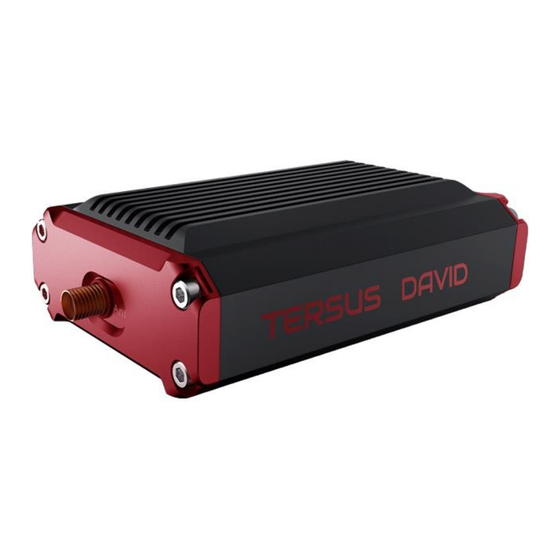
Tersus David Palm-sized GNSS receiver Manuals
Manuals and User Guides for Tersus David Palm-sized GNSS receiver. We have
3
Tersus David Palm-sized GNSS receiver manuals available for free PDF download: User Manual, Quick Start Manual
Tersus David User Manual (103 pages)
Brand:
Tersus
| Category:
Receiver
| Size: 3 MB
Table of Contents
User Manual
1
Revision History
2
Table of Contents
3
Table of Content
3
List of Figures
6
List of Tables
10
Table 1 Document / Software Used in this User Manual
11
Notices
11
1 Overview
13
Introduction
13
Figure 1.1 Outlook of David GNSS Receiver
13
Receiver Features
14
Brief Introduction of GNSS and RTK
14
Figure 1.2 Outline of David System
15
Figure 1.3 Corrections Transmitted Via Internet
15
Figure 1.4 Corrections Transmitted with Radios
16
2 Devices in David Package
17
Figure 2.1 Devices in the Box
17
Table 2 Five David Variants
17
Figure 2.2 Rover Kit Network Mode
18
Rover Kit Network Mode
18
Figure 2.18 Power Bank
19
Table 3 Devices in Rover Network Mode
19
David GNSS Receiver
20
Figure 2.3 David GNSS Receiver
20
Table 4 Definition of Leds
20
AX3702 GNSS Antenna
21
Figure 2.4 AX3702 GNSS Antenna
21
Figure 2.5 TNC-J to SMA Cable 1.5M (GNSS Antenna Cable)
21
COMM1-Bluetooth Module
22
DC-2Pin to USB Power Cable
22
Figure 2.6 GNSS Antenna Connector
22
Figure 2.7 DC-2Pin to USB Power Cable
22
Figure 2.8 COMM1-Bluetooth Module
22
COMM2-7Pin to USB & DB9 Cable
23
Figure 2.9 COMM2-7Pin to USB & DB9 Cable
23
Table 5 Functions of COMM2-7Pin to USB & DB9 Cable
23
DB9 Male to USB Type a Male Converter Cable
24
Figure 2.10 DB9 Male to USB Type a Male Converter Cable
24
Figure 2.11 USB Type a Female to USB (Micro + Type C) OTG Cable
24
USB Type a Female to USB (Micro + Type C) OTG Cable
24
Figure 2.12 Height Measure Accessory
25
Figure 2.13 Wrench
25
Height Measure Accessory
25
Other Accessories
25
Wrench
25
Figure 2.14 Bracket for Rover
26
Figure 2.15 Ranging Pole
26
Figure 2.16 Magic Tape
26
Figure 2.17 Carrying Case for Rover
27
Figure 2.19 Rover Kit with 2W Radio Station
28
Table 6 Rover Kit with 2W Radio Station
29
460Mhz Radio
30
Figure 2.20 2W/460Mhz Radio
30
Table 7 Button Description for 2W/460Mhz Radio
30
460Mhz Radio Antenna
31
Figure 2.21 2W/460Mhz Radio Antenna
31
Table 8 LED Definition
31
COMM2-7Pin to USB & 2W-Radio-5Pin Cable
32
Figure 2.22 COMM2-7Pin-USB & 2W-Radio-5Pin Cable
32
Figure 2.23 TNC-J to TNC-J Cable 1.0M (Radio Antenna Extension Cable)
32
TNC-J to TNC-J Cable 1.0M (Radio Antenna Extension Cable)
32
Bracket for 460M Antenna with TNC-TNC Converter
33
Rover Kit with 2W Radio Station
28
Base Kit Network Mode
33
Figure 2.24 Bracket for 460M Antenna with TNC - TNC Converter
33
Figure 2.25 Base Kit Network Mode
34
Bracket for Base
35
Figure 2.26 Bracket for Base
35
Tape Measure
35
Other Accessories
36
Base Kit with 2W Radio Station
36
Figure 2.27 Tape Measure
36
Figure 2.28 Carrying Case for Base
36
Figure 2.29 Base Kit with 2W Radio
37
Bullet-DC to Alligator Clip
39
DC-2Pin to Bullet-DC Power Cable
39
Figure 2.30 DC-2Pin to Bullet DC Power Cable
39
Figure 2.31 Bullet-DC to Alligator Clips
39
High Gain Radio Antenna
39
Figure 2.32 High Gain Radio Antenna
40
Figure 2.33 Metal Plate for Radio Antenna
40
Figure 2.34 Telescopic Pole for Radio Antenna
40
Metal Plate for Radio Antenna
40
Telescopic Pole for Radio Antenna
40
Bracket for Mobile
41
Figure 2.35 Hook and Screws for 2W Radio (Attached to 2W Radio)
41
Figure 2.36 Hook and Screws for David (Attached to David)
41
Hook and Screws for 2W Radio
41
Hook and Screws for David
41
Other Accessories
42
Base Kit with 30W Radio Station
42
Figure 2.37 Bracket for Mobile
42
Figure 2.38 Toolbag
42
Figure 2.39 Base Kit with 30W Radio
43
Table 9 Base Kit with 30W Radio Station
44
Figure 2.40 30W Radio Station
45
Radio
45
Table 10 Definition of the Control Buttons
45
Table 11 Definition of Leds
45
COMM2-7Pin to USB & 30W-Radio-5Pin Cable
46
DC-2Pin & 30W-Radio-DC-2Pin to Bullet-DC
46
Figure 2.41 DC-2Pin & 30W-Radio-DC-2Pin to Bullet-DC
46
Figure 2.42 COMM2-7Pin to USB & 30W-Radio-5Pin Cable
46
3 General Operation
47
Install the GNSS Antenna
47
Power on David
47
Communication between Android Phone and David
49
Wires Connection
49
Figure 3.1 Outline of Android Phone to David with Wires
49
Figure 3.2 Connect Using USB Cable
50
External Bluetooth Connection
51
Figure 3.3 Outline of Android Phone to David with Bluetooth
51
Figure 3.4 Connect Using Bluetooth
52
Figure 3.5 Search Bluetooth Device
52
Firmware Update
53
Hardware Connection
53
USB to Serial COMM Port Driver
53
Figure 3.6 Outline of David Connected to a Computer
53
Figure 3.7 COM Port Is Recognized by the Computer in the Computer
55
Figure 3.8 Update Driver Software Manually
55
Management
55
Firmware Update
56
Figure 3.9 Two Methods of Searching for Driver Software
56
Figure 3.10 PC Software Icons on Desktop
57
Figure 3.11 Firmware Settings in Tersusupdate Software
57
Figure 3.12 Update Progress of the Firmware Update
58
Figure 3.13 Firmware Update Successful Interface
58
Figure 3.14 Advance Setting for Firmware Update
60
Auth Code
61
Download Files from Internal EMMC Card
62
Figure 3.15 Device Information Interface on Nuwa App
62
Figure 3.16 Download File from EMMC Card
62
Figure 3.17 File Download Using Tersusdownload
63
Figure 3.18 Select Serial Port for Download Port
63
Input Command Directly to the GNSS Board
64
Figure 3.19 Select Download Speed
64
Figure 3.20 File Downloading in Process
64
Figure 3.21 Input Command in Data Terminal on Nuwa App
65
4 Introduction of Nuwa
66
Figure 4.1 Booting up Page of Nuwa App
66
Figure 4.2 Nuwa App Interface 1 - Project
67
Figure 4.3 Nuwa App Interface 2 - Device
67
Figure 4.4 Nuwa App Interface 3 - Survey
68
Figure 4.5 Nuwa App Interface 4 - Tools
68
5 Specification
69
David Receiver
69
Table 12 David GNSS Performance
69
Figure 5.1 Panel of David
71
Figure 5.2 Pin Definition of the COMM1/COMM2/DC Ports
71
Table 13 Pin Definition of Connectors on David
71
Antenna AX3702
72
Table 14 Antenna AX3702
72
Radio RS400L2
73
Table 15 Specifications of 2W Radio RS400L2
73
Table 16 Default Factory Configuration for RS400L2
75
Radio RS400L30
76
Table 17 Specifications of 5W Radio RS400L30
76
Table 18 Default Factory Configuration for RS400L30
78
6 Typical Operation
79
David as a Rover to Receive Corrections from Internet
80
Figure 6.1 Outline of Android Phone to David with Wire - Rover
80
Figure 6.2 Connect David Via USB
81
Figure 6.3 Rover Setting Interface
82
Figure 6.4 Edit Rover Configuration
82
Figure 6.5 Rover Is Receiving RTK Corrections
82
David as a Base to Transmit Corrections to Internet
83
Figure 6.6 Outline of Android Phone to David with Wire - Base
83
Figure 6.7 Connect David Via USB
84
Figure 6.8 Base Setting Interface
85
Figure 6.9 Edit Base Configuration
85
Figure 6.10 Base Is Transmitting Corrections
85
Radios Transmit RTK Corrections between Two David Receivers
86
Figure 6.11 Outline of Base/Rover with Radios
86
Figure 6.12 Base Work Mode List
88
Figure 6.13 Edit Base Configuration
88
Figure 6.14 Rover Work Mode List
89
Figure 6.15 Edit Rover Configuration
89
Data Collection for Post Processing
90
Figure 6.16 Outline of Static Data Collection
91
Figure 6.17 Survey Interface on Nuwa App
92
Figure 6.18 Static Survey Configuration
92
Auto Base Station List Function
93
Figure 6.19 Auto Base Station List Interface
93
Figure 6.20 Fixed Position for Base Station
94
Radio Operation
95
Figure 6.21 Front Panel of the 2W Radio
95
Radio Operation
98
Figure 6.22 Front Panel of the 30W Radio
98
7 Terminology
101
Table 19 List of Terminology
101
Advertisement
Tersus David User Manual (76 pages)
Brand:
Tersus
| Category:
Receiver
| Size: 3 MB
Table of Contents
Table of Contents
2
Table 1 the Document / Software Used in this User Manual
7
1 Overview
9
Introduction
9
Receiver Features
9
Figure 1 Outlook of David GNSS Receiver
9
Brief Introduction of GNSS and RTK
10
Figure 2 Outline of David System
10
Figure 3 Corrections Transmitted Via Internet
11
Figure 4 Corrections Transmitted with Radios
11
2 Devices in David Package
12
Figure 5 David in the Box
12
Table 2 Seven David Variants
12
Figure 6 Field Photo 1 - 1
13
Rove Kit Mobile Mode
13
Figure 13 Bracket for Rover
14
Figure 16 USB Type a Male to DB9 Male Cable
14
Figure 17 USB Type a Male to USB Type a Male Cable
14
Table 3 Devices in Rover Mobile Mode
14
David Receiver
15
Figure 8 David Receiver
15
GNSS Antenna
15
Table 4 Definition of Leds
15
Figure 10 RF Cable
16
Figure 9 AX3702 (HG) Antenna
16
The 2Pin-USB Power Cable
16
Bracket for Rover
17
COMM1-Bluetooth Module
17
Figure 11 2Pin-USB Power Cable
17
Figure 12 Bluetooth Module
17
COMM2-7Pin-USB & DB9 Data Cable
18
Figure 14 GNSS Antenna Connector
18
GNSS Antenna Connector
18
Figure 15 COMM2-7Pin-USB & DB9 Data Cable
19
Other Accessories
19
Table 5 Functions of COMM2-7Pin-USB & DB9 Data Cable
19
Figure 18 USB Type a Female to USB (Micro + Type C) OTG Cable
20
Figure 19 Height Measure Accessory
20
Figure 7 Field Photo 1 - 2
14
Figure 20 Battery Bank
21
Figure 21 Field Photo 2 - 1
21
Rover Kit with 1W Radio Station
21
Figure 22 Field Photo 2-2
22
Table 6 Rover Kit with 1W Radio Station
22
RS900C 1W/915Mhz Radio
23
Figure 23 RS900C 1W Radio Station
23
Rover Kit with 2W Radio Station
23
Table 7 LED Definition
23
Figure 24 Field Photo 3 - 1
24
Figure 25 Field Photo 3 - 2
24
RS400L2 2W/460Mhz Radio
25
Table 8 Rover Kit with 2W Radio Station
25
Figure 26 2W /460Mhz Radio
26
Table 9 Button Manual
26
COMM2-7Pin-USB & 5Pin Cable
27
Base Kit Mobile Mode
27
Figure 27 COMM2-7Pin-USB & 5Pin Cable
27
Table 10 LED Definition
27
Figure 28 Field Photo 4
28
Table 11 Base Kit Mobile Mode
28
Bracket for Base
29
Tape Meter
29
Base Kit with 1W Radio Station
30
Figure 31 Field Photo 5
30
Base Kit with 2W Radio Station
31
Figure 29 Bracket for Base
31
Figure 30 Tape Meter
31
Table 12 Base Kit with 1W Radio Station
31
Base Kit with 30W Radio Station
32
Figure 32 Field Photo 7 - 1
32
Figure 33 Field Photo 7 - 2
33
Table 13 Base Kit with 30W Radio Station
33
Figure 34 30W Radio Station
34
Radio
34
Table 14 the Definition of the Control Buttons
34
Figure 35 Power Cable for 30W Radio
35
Other Cables
35
Table 15 Definition of Leds
35
Figure 36 COMM Cable for 30W Radio
36
Figure 37 David GNSS Receiver Installation Hook
36
3 General Operation
37
Install the GNSS Antenna
37
Power on David
37
Communication between Android Phone and David
38
With Wires
39
Figure 38 Outline of Android Phone to David with Wires
39
Table 16 Detailed Steps
40
With an External Bluetooth
41
Figure 39 Outline of Android Phone to David with Bluetooth
41
Table 17 Detailed Steps
41
FW Upgrade & Auth Code
42
Figure 40 Outline of David Connected to a Computer
42
Firmware Updates
43
Table 18 Preparation for FW Update
43
Table 19 Detailed Steps for FW Update
44
Auth Code
46
Download Files from Internal Emmc Card
47
Figure 41 Download File from Emmc Card
47
Table 20 Detailed Steps to Download Files from Emmc Card
47
Input Command Directly to the GNSS Board
50
Table 21 Input Commands to the BX306 Directly
50
4 Introduction of Nuwa
52
Figure 42 Booting up Page
52
Figure 43 Four Main Windows of Nuwa
53
5 Specification
54
David Receiver
54
Table 22 David GNSS Performance
54
Figure 44 Panel of David
55
Figure 45 Pin Definition of the COMM1/COMM2/DC Ports
56
Table 23 Pin Definition
56
Antenna Ax3702 (Hg)
57
Table 24 Antenna AX3702 (HG)
57
Radio RS900C
58
Table 25 Specification for RS900C
58
Radio RS400L2
60
Table 26 Specification for RS400L2
60
Radio RS400L30
62
Table 27 RS400L30 Radio Specification
62
6 Typical Operating
65
David as a Rover to Receive Corrections from Internet
65
Figure 46 Outline of Android Phone to David with Wire
66
Table 28 Detailed Steps for Rover Receive Corrections from Internet
66
David as a Base to Transmit Corrections to Internet
68
Figure 47 Outline of Android Phone to David with Wire
68
Table 29 Detailed Steps for Base Transmit Corrections to Internet
69
Radios Transmit RTK Corrections between Two Davids
71
Figure 48 Outline of Base/Rover with Radios
71
Table 30 Detailed Steps for David with Radios
71
Data Collection for Post Processing
73
Figure 49 Outline of Static Data Collection
74
Table 31 Detailed Steps for Static Data Collection
74
7 Terminology
76
Table 32 List of Terminology
76
Tersus David Quick Start Manual (13 pages)
Brand:
Tersus
| Category:
Receiver
| Size: 1 MB
Table of Contents
System Structure
2
Rover Kit Network Mode
3
Base Kit Network Mode
5
Base Kit with 2W Radio
6
Base Kit with 30W Radio
7
Exemption of Liability
12
Technical Support
12
Advertisement
Advertisement
Related Products
TERSUS David30
Tersus BX Series
Tersus BX306
Tersus BX306Z
Tersus BX316
Tersus BX316D
Tersus BX316R
TERSUS BX50L-TAP
TERSUS LUKA
Tersus NeoRTK
Tersus Categories
Receiver
Radio
Controller
Cell Phone
Network Hardware
More Tersus Manuals
Login
Sign In
OR
Sign in with Facebook
Sign in with Google
Upload manual
Upload from disk
Upload from URL