Table of Contents
Advertisement
Quick Links
Advertisement
Table of Contents

Related Manuals for TERSUS David30


Summary of Contents for TERSUS David30
- Page 1 User Manual Version V2.0-20210721 User Manual For David30 GNSS Receiver ©2021 Tersus GNSS Inc. All rights reserved. Sales Enquiry: sales@tersus-gnss.com Technical Support: support@tersus-gnss.com More details, please visit www.tersus-gnss.com...
-
Page 2: Revision History
User Manual for David30 GNSS Receiver v2.0 Revision History Version Revision Date Change summary 20210427 Initial Release 20210721 Add CE&FCC marks and section7; upgrade the information of 2W radio RS460H and 28w radio RS400H3. -
Page 3: Table Of Contents
User Manual for David30 GNSS Receiver v2.0 Table of Content Revision History........................1 Table of Content........................2 List of Figures........................... 5 List of Tables..........................8 Notices............................9 1. Overview..........................12 1.1 Introduction........................12 1.2 Receiver Features.......................13 1.3 Brief Introduction of GNSS and RTK............... 13 2. - Page 4 2.5.2 28W-Radio power cable..................39 3. General operation......................40 3.1 Install the GNSS antenna..................40 3.2 Power on David30.......................41 3.3 Communication between Android device and David30........42 3.4 Firmware Update......................44 3.4.1 Hardware Connection..................44 3.4.2 USB to Serial COMM Port driver...............44 3.4.3 Firmware Update....................
- Page 5 5.4 28W Radio RS400H3....................64 6. Typical operation....................... 67 6.1 David30 as a Rover to receive corrections from Internet........68 6.2 David30 as a Base to transmit corrections to Internet.......... 72 6.3 Radios Transmit RTK Corrections between Two David30........77 6.4 Data Collection for Post Processing................
-
Page 6: List Of Figures
Figure 2.8 Magic Tape ................. 24 Figure 2.9 Ranging Pole................24 Figure 2.10 Carrying Case for Rover ............25 Figure 3.3 Outline of Android device to David30 with Bluetooth.... 42 Figure 3.4 Connect using Bluetooth............43 Figure 3.5 Search Bluetooth device............43 Figure 3.6 Outline of David30 connected to a Computer......44... - Page 7 Figure 5.1 Panel of David30 ............... 60 Figure 5.2 Pin Definition of the COMM1/COMM2/DC ports ....60 Figure 6.1 Outline of Android device to David30 with Wire – Rover ..68 Figure 6.2 Connect David30 via USB............69 Figure 6.3 Rover setting interface............... 70 Figure 6.4 Edit Rover configuration.............70...
- Page 8 User Manual for David30 GNSS Receiver v2.0 Figure 6.19 Auto Base Station List interface..........85 Figure 6.20 Fixed position for base station..........86 Figure 6.21 Front Panel of the 2W Radio...........87 Figure 6.22 Transmit power................94 Figure 6.23 Serial baud rate self-adaption..........95...
-
Page 9: List Of Tables
Table 7 Base Kit with 2W Radio Station............32 Table 8 Definition of LED indicators............... 11 Table 9 David30 GNSS Performance............60 Table 10 Pin Definition of connectors on David30........62 Table 11 Antenna AX4E02................11 Table 12 Specifications of 2W Radio RS460H..........64 Table 13 Default factory configuration for RS460H........ -
Page 10: Notices
The Declaration of Conformity may be obtained from Tersus GNSS Inc. FCC Notices The David30 GNSS Receiver has been tested and found to comply with the radiated and conducted emission limits under FCC Rules and Regulations Part 15B for a Class A digital device. The Class A limits are designed to provide reasonable protection against harmful interference in a residential installation. - Page 11 A warning that actions, operations or configurations may result in regulatory noncompliance, safety issues or equipment damage. NUWA is Tersus survey app, four tabs (Project, Device, Survey and Tools) are provided in the Nuwa main interface. All the operations in the Survey software start from these four tabs.
-
Page 12: Table 1 Document / Software Used In This User Manual
Tersus Geomatics Post processing tool for static data https://www.tersus-gnss.com/software/D Office avid30-receiver Support If there is any problem and the information needed cannot be found in the product documentation, request technical support using the Tersus website at www.tersus-gnss.com, or mail to support@tersus-gnss.com... -
Page 13: Overview
Tersus David30 is a cost-efficient, palm-sized GNSS receiver, mainly for the mass survey market, and also for UAV / AGV / Agriculture application. Nuwa, a survey app on Android system, works with David30 for the survey. And David30 receiver can communicate with an Android platform such as a device or tablet via USB cable or an external Bluetooth module. -
Page 14: Receiver Features
IP67 for water & dust proof, work reliably in harsh condition Brief Introduction of GNSS and RTK Tersus BX40C GNSS board is integrated in David30, the board is receiving the GNSS signals from satellites and RTK corrections from the base, and is outputting cm-level position, velocity and time. -
Page 15: Figure 1.2 Outline Of David30 System
Figure 1.2 Outline of David30 System The RTK corrections are transmitted from a base, which can be a CORS station or a David30 receiver. The RTK corrections can be transmitted to the rover via Internet or with external radios. Figure 1.3 Corrections transmitted via Internet... -
Page 16: Figure 1.4 Corrections Transmitted With Radios
User Manual for David30 GNSS Receiver v2.0 Figure 1.4 Corrections transmitted with radios If RTK corrections are transmitted via Internet, an Android device or controller will be included in the RTK system to transmit/receive the RTK corrections, refer to section 6.1 and section 6.2 for detailed operations. -
Page 17: Devices In David30 Package
2. Devices in David30 Package This chapter is to give detailed introduction about all the devices in the package. David30 has five variants, which are convenient for customers to select according to their application. Different accessories are included in each variant. -
Page 18: Rover Kit Network Mode
User Manual for David30 GNSS Receiver v2.0 Rover Kit Network Mode In this variant, the David30 is connected to an Android device or controller with Bluetooth module or with cables. Tersus Survey Nuwa app is installed and run in the Android device or controller to receive RTK corrections from a NTRIP caster or a TCP server. -
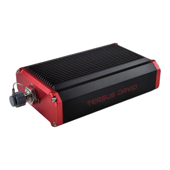
Page 19: David30 Gnss Receiver
COMM2 port Figure 2.2 David30 GNSS Receiver The DC port of David30 is for power input and CAN port, COMM1 port is for COM1, PPS and Event, and COMM2 port is for COM2 and USB ports, refer to section 5.1 for detailed specification of David30. -
Page 20: Ax4E02 Gnss Antenna
User Manual for David30 GNSS Receiver v2.0 2.1.2 AX4E02 GNSS Antenna AX4E02 GNSS antenna is used to receive the RF signal from the satellites, and it must be connected to the David30 with the GNSS antenna cable in the package. Figure 2.3 AX4E02 If an antenna from other companies is used, contact Tersus to obtain permission, or the David30 receiver may not work as expected. -
Page 21: Dc-5Pin Power Cable
2. The Serial-5pin to DC JACK & DB9 Male cable and the DC JACK male with two wires (the brown wire connects to power and the blue wire connects to ground) below are optional. It is to power David30 receiver using external power source, which is not included in the package. -
Page 22: Comm1-Bluetooth Module
Figure 2.10 COMM1-Bluetooth Module The Bluetooth can only be installed to the COMM1 port of David30. This Bluetooth module is used to connect to the COMM1 port of David30 receiver. The SSID of this Bluetooth module is BT420R-xxxxx_xxxxxx, where the first xxxxx is the last 5 digits of the Bluetooth serial number, which is printed on the Bluetooth module. -
Page 23: Db9 Male To Usb Type A Male Converter Cable
The other function of this cable is to connect to USB Type A Female to USB (Micro +Type C) OTG cable (refer to Figure 2.12) to connect the Android device or controller with David30, refer to section 3.3.1. Figure 2.11 COMM2-7pin to USB & DB9 Cable The COMM2-7pin to USB &... -
Page 24: Usb Type A Female To Usb (Micro + Type C) Otg Cable
User Manual for David30 GNSS Receiver v2.0 2.1.7 USB Type A Female to USB (Micro + Type C) OTG cable This cable is to connect the device output with USB type A male connector to an android device with micro or type C interface. -
Page 25: Figure 2.7 Bracket For Rover
User Manual for David30 GNSS Receiver v2.0 Figure 2.15 Bracket for Rover Figure 2.16 Magic Tape Figure 2.17 Ranging Pole... -
Page 26: Figure 2.10 Carrying Case For Rover
Figure 2.18 Carrying Case for Rover A power source can be used to power on the David30, however it is not included in the package, and is to be prepared by the customers, refer to section Power on David30 for more details. -
Page 27: Rover Kit With 2W Radio Station
User Manual for David30 GNSS Receiver v2.0 Rover Kit with 2W Radio Station In this variant, the David30 receiver is connected to an external 2W radio to receive RTK corrections from a base. With an external Bluetooth or cables, the David30 receiver is connected to an Android device or controller, which runs Tersus Survey software Nuwa to configure the David30 GNSS receiver. -
Page 28: Radio Rs460H
User Manual for David30 GNSS Receiver v2.0 2.2.1 2W Radio RS460H This radio works at 410~470MHz frequency, the max output power of this radio is 2W and the typical range is 5km. Refer to chapter 5 for specification details. Figure 2.18 2W Radio RS460H... -
Page 29: 410-470Mhz Radio Whip Antenna
User Manual for David30 GNSS Receiver v2.0 Table 6 LED Definition Description RED: 2W output is selected, GREEN: 1W output is selected. Blink RED: data is transmitting. Blink GREEN: data is receiving. GREEN: Transparent protocol is selected. RED: TT450 protocol is selected. -
Page 30: Tnc-J To Tnc-J Cable 1.0M (Radio Antenna Extension Cable)
User Manual for David30 GNSS Receiver v2.0 David30 receiver to the 2W radio station & an Android device. The length of the cable is 0.55m. Figure 2.20 COMM2-7pin-USB & 2W-Radio-5pin Cable COMM2-7pin to USB & 2W-Radio-5pin Cable can only be installed into the COMM2 port of David30. -
Page 31: Bracket For 2W Radio Antenna With Tnc-Tnc Converter
Figure 2.22 Bracket for 2W radio antenna with TNC – TNC converter Base Kit Network Mode In this variant, the David30, working as a base, transmits RTK corrections to a NTRIP caster or a TCP sever. The David30 is connected to an Android device with an external Bluetooth or with cables. -
Page 32: Tape Measure
User Manual for David30 GNSS Receiver v2.0 Figure 2.23 Bracket for Base 2.3.2 Tape Measure Working with height measure accessory, the tape measure gives position of a point on ground with mm-level accuracy. Figure 2.24 Tape Measure 2.3.3 Other accessories A yellow carrying case marked with GNSS BASE is to store all the devices and accessories of base kit. -
Page 33: Base Kit With 2W Radio Station
User Manual for David30 GNSS Receiver v2.0 Base Kit with 2W Radio Station In this variant, the David30, working as a base, transmits RTK corrections to an external 2W radio. The David30 is connected to an Android device with cables or with the Bluetooth module. Tersus Survey Nuwa app is installed in the Android device to configure the David30. -
Page 34: Table 7 Base Kit With 2W Radio Station
User Manual for David30 GNSS Receiver v2.0 The two tripods and the tribrach in Figure 2.26 are not included in the package. Power bank of 5V output is not suitable to supply power for Base kit with 2W Radio, a large battery of 12V output is recommended. -
Page 35: Dc-5Pin Power Cable
User Manual for David30 GNSS Receiver v2.0 2.4.1 DC-5pin Power cable The DC-5pin of this cable is to connect to the DC port of David30 receiver, the Serial-5pin to DC JACK & DB9 Male cable in the figure below. Figure 2.27 Serial-5pin to DC JACK & DB9 male cable 2.4.2 DC JACK male... -
Page 36: Metal Plate For Radio Antenna
User Manual for David30 GNSS Receiver v2.0 Figure 2.29 High Gain Radio Antenna 2.4.4 Metal plate for radio antenna This metal plate is used to fixate the radio antenna to the tripod. Figure 2.30 Metal plate for radio antenna 2.4.5 Telescopic pole for radio antenna The telescopic pole is used to extend the height for radio antenna. -
Page 37: Hook And Screws For 2W Radio
Figure 2.32 Hook and Screws for 2W Radio (attached to 2W radio) 2.4.7 Hook and Screws for David30 The hook and screws below are attached to David30 receiver for hanging on the tripod. Figure 2.33 Hook and Screws for David30 (attached to David30) 2.4.8 Bracket for Mobile... -
Page 38: Other Accessories
Figure 2.35 Tool bag Base Kit with 28W Radio RS400H3 In this variant, the David30, working as a base, transmits RTK corrections to an external 28W radio RS400H3. The David30 is connected to an Android device with cables or with the Bluetooth module. Tersus Survey Nuwa app is installed in the Android device to configure the David30. -
Page 39: Radio Rs400H3
User Manual for David30 GNSS Receiver v2.0 Install the radio antenna before switching the radio transceiver to transmit mode, or the radio transceiver may be damaged due to overheating. The energy to be transmitted cannot be emitted out without the antenna, which may cause the temperature rise and overheat of the radio module. -
Page 40: Radio Power Cable
The DC-5pin of the 28W-Radio power cable is to connect to the DC port of David30 receiver, the 28W-Radio-DC-5pin of this cable is to connect to the DC port of 28W radio, and the Bullet-DC is to connect with Bullet-DC to Alligator Clips in Figure 2.28. -
Page 41: General Operation
User Manual for David30 GNSS Receiver v2.0 3. General operation The general operation of David30 is related to the Tersus Survey Nuwa application, which is introduced in the software manual. This chapter describes how to do the hardware connection only. -
Page 42: Power On David30
After power on, the SV LED is ON for 3 to 5 seconds, then it turns OFF, which means the David30 is booting up successfully. If the SV LED is NOT acting as the above steps, it means the David30 is NOT booting up successfully. -
Page 43: Communication Between Android Device And David30
The detailed steps are described as follows: 1. Install the Bluetooth module to the COMM1 port of David30. 2. Connect the AX4E02 GNSS antenna to David30 with the GNSS antenna cable. 3. Power on the David30 receiver with a power supply. -
Page 44: Figure 3.4 Connect Using Bluetooth
User Manual for David30 GNSS Receiver v2.0 Figure 3.4 Connect using Bluetooth Figure 3.5 Search Bluetooth device A Bluetooth device can be removed from the Available Device list by pressing it for a few seconds. -
Page 45: Firmware Update
3.4.2 USB to Serial COMM Port driver After completing the hardware connection, David30 receiver is powered on automatically when the power cable is connected to a power source. Simultaneously the computer recognizes the COM port in the Computer... -
Page 46: Figure 3.7 Com Port Is Recognized By The Computer In The Computer
In the situations of automatic search failed and the computer not connecting to the internet, select [Browse my computer for driver software] and browse the location of the driver software which is downloaded from Tersus website https://www.tersus-gnss.com/software. Figure 3.7 COM port is recognized by the computer in the Computer Management... -
Page 47: Firmware Update
Figure 3.8 Update Driver Software manually Figure 3.9 Two methods of searching for driver software 3.4.3 Firmware Update The updated firmware is released and available for downloading on Tersus web site https://www.tersus-gnss.com/software, or it can be obtained from Tersus technical support. -
Page 48: Figure 3.10 Pc Software Icons On Desktop
User Manual for David30 GNSS Receiver v2.0 The firmware version of the current David30 receiver can be examined in Tersus GNSS Center by typing ‘LOG VERSION’ in the command area, and in Nuwa app by clicking [Device] -> [Device Info]. -
Page 49: Figure 3.11 Firmware Settings In Tersusupdate Software
User Manual for David30 GNSS Receiver v2.0 Figure 3.11 Firmware Settings in TersusUpdate software 3. The firmware is updating in progress as shown in Figure 3.12 below. Do not power off the receiver during the verification and update progress. Figure 3.12 Update Progress of the firmware update... -
Page 50: Figure 3.13 Firmware Update Successful Interface
5. Click [OK] and [Finish] to close the firmware update window. The receiver would reset automatically. 6. After the David30 receiver is boot up, the current firmware version can be checked in Tersus GNSS Center by typing ‘LOG VERSION’ in the command area, and in Nuwa app by clicking [Device] ->... -
Page 51: Figure 3.14 Advance Setting For Firmware Update
If the [Advance Setting] is checked, select [Manual Hardware Reset] in the pop-up window and click [OK]. Click [Next] in the previous interface, power off the David30 receiver, wait for five seconds and power on the receiver again. Figure 3.14 Advance Setting for firmware update After firmware update is finished, power off the receiver, wait for five seconds and power on the receiver again. -
Page 52: Auth Code
User Manual for David30 GNSS Receiver v2.0 Auth Code An auth code is used to determine the features and valid time for a David30 receiver. If the auth code is expired, the receiver will not work. To get a new auth code to register, check information as follows: 1. -
Page 53: Download Files From Internal Emmc
User Manual for David30 GNSS Receiver v2.0 3. Or connect the David30 with Nuwa app, click [Device] -> [Device Info] to get the register info. Copy the auth code in the registration file and paste it to the TersusSurvey folder of the android device, click [Register] to complete the registration and the auth code will be shown in the window below. -
Page 54: Input Command Directly To The Gnss Board
Figure 3.17 Download file from eMMC The detailed steps of downloading files from eMMC are as follows: 1. Connect the COMM2 port of David30 receiver to the USB port of a computer using COMM2-7pin to USB & DB9 cable or COMM2-7pin to USB &... - Page 55 User Manual for David30 GNSS Receiver v2.0 configure the receiver, the steps are described as below. 1. Follow the instructions in section 3.3.1 or section 3.3.2 to connect the android device to the David30 receiver. 2. Run Nuwa app, click [Device] -> [Data Terminal].
-
Page 56: Introduction Of Nuwa
Nuwa is the Tersus survey app, which runs in an Android device. All the configuration commands for David30 are input of Nuwa, and all the operations of David30 are completed on Nuwa. Four menu tabs are provided in the main interface which are Project, Device, Survey and Tools. Refer to the user manual for Nuwa app for details. -
Page 57: Figure 4.2 Nuwa App Interface 1 - Project
User Manual for David30 GNSS Receiver v2.0 problems to run Nuwa app. 2) Nuwa is tested with: Huawei Mate 7/Honor 7/9, Oppo A57, Vivo X9, Samsung C7 Pro and Tersus TC20 Controller. 3) It is highly recommended that an Android device with better hardware performance than those above is used to run Nuwa app. -
Page 58: Figure 4.4 Nuwa App Interface 3 - Survey
User Manual for David30 GNSS Receiver v2.0 Figure 4.4 Nuwa app interface 3 – Survey Figure 4.5 Nuwa app interface 4 – Tools... -
Page 59: Specification
User Manual for David30 GNSS Receiver v2.0 5. Specification 5.1 David30 Receiver Table 9 David30 GNSS Performance GNSS Performance Signal tracking GPS L1 C/A, L2C, L2P, L5; GLONASS L1 C/A, L2 C/A; BeiDou B1I, B2I, B2a, B3I; Galileo E1, E5a, E5b; QZSS L1 C/A, L2C, L5 1.5m RMS (Horizontal) - Page 60 User Manual for David30 GNSS Receiver v2.0 Mechanical Drawing Environmental Operating Temperature -40C to +70C Storage Temperature -40C to +85C Humidity MIL-STD-810G, Method 507.5 Procedure II (95%) Random Vibration MIL-STD 810G Method 514.6, Category 24 (7.7 g RMS) Sinusoidal Vibration...
-
Page 61: Figure 5.1 Panel Of David30
Table 10 Pin Definition of connectors on David30 COMM1 COMM2 Connector Pin No. RS-232 RS-232 TXD3 TXD1 TXD2 RXD3 RXD1 RXD2 USB D+ EVENT USB D- The pin definition’s view from outside to David30 is as below. Figure 5.2 Pin Definition of the COMM1/COMM2/DC ports... -
Page 62: Antenna Ax4E02
User Manual for David30 GNSS Receiver v2.0 5.2 Antenna AX4E02 Table 11 Antenna AX4E02 Antenna Specification GPS L1/L2/L5/L-Band, GLONASS L1/L2/L3, Tracking signals BeiDou B1/B2/B3, Galileo E1/E5a/E5b/E6, QZSS L1/L2/L5/L6, SBAS L1/L5 and IRNSS L5 Impedance 50 Ohm Polarization RHCP Axial Ratio ≤... -
Page 63: Radio Rs460H
User Manual for David30 GNSS Receiver v2.0 Storage temperature -55C - +85C Damp 45% - 95% Mechanical Drawing 5.3 2W Radio RS460H Table 12 Specifications of 2W Radio RS460H Voltage and Power Input voltage DC 5 ~ 12V 6W (DC 5V, transmitting power 2W) - Page 64 User Manual for David30 GNSS Receiver v2.0 Low power (1W) 30.5 1.0dBm @ DC5V Power stability 1dB Sensitivity 115dBm@BER 10 , 9600bps Co-channel rejection >-12dB Adjacent channel selectivity >50dB@25KHz Distance(Typical) 5-7KM Modem Air baud rate 19200/9600/4800bps Serial baud rate 115200/38400(default)/19200/9600bps...
-
Page 65: Radio Rs400H3
User Manual for David30 GNSS Receiver v2.0 Table 13 Default factory configuration for RS460H Channel Frequency 457.550MHz 458.050MHz 458.550MHz 459.050MHz 459.550MHz 460.550MHz 461.550MHz 462.550MHz 463.550MHz 464.550MHz Customized frequency 410~470MHz 5.4 28W Radio RS400H3 Table 14 Specifications of 28W Radio RS400H3... - Page 66 User Manual for David30 GNSS Receiver v2.0 Modem Air baud rate 4800bps, 9600bps, 19200bps Modulation Type GMSK/4FSK Serial port baud rate 9600bps, 19200bps, 38400bps, 57600bps, 115200bps Protocol TrimTalk, TrimMark3, Transparent-EOT, Satel Environmental Operating -40 ~ +65C Temperature Storage -50 ~ +85C...
- Page 67 User Manual for David30 GNSS Receiver v2.0 Pin 1: PWR (9~16V DC) Pin 2: Power GND Data & power interface Pin 3: RXD Pin 4: Signal GND Pin 5: TXD View from outside to radio Table 5 Default factory configuration for RS400H3...
-
Page 68: Typical Operation
An external large capacity power if a base kit with 28W or with 2W radio station is used. A tripod (optional). A tribrach (optional) It is highly recommended that a David30 base variant is installed on a tripod. It is normal that the metal case of David30 is hot during operation. -
Page 69: David30 As A Rover To Receive Corrections From Internet
1. Install the GNSS antenna on a ranging pole at a designated point. 2. Connect the antenna to David30 with the GNSS antenna cable. 3. Connect the COMM2 port of David30 to the USB port of an android device... -
Page 70: Figure 6.2 Connect David30 Via Usb
6. Select [Bluetooth] in the option list of Connect Type as shown in Figure 6.2. 7. Click [Connect Config] to update configuration accordingly. 8. Click [Connect] to enable the communication with David30. 9. Back to [Device] -> [Rover] 10. Select [Default: PDA Network+Default Server1] as shown in Figure 6.3, click [Detail] to configure the parameters of the Network. -
Page 71: Figure 6.3 Rover Setting Interface
User Manual for David30 GNSS Receiver v2.0 Figure 6.3 Rover setting interface Figure 6.4 Edit Rover configuration... -
Page 72: Figure 6.5 Rover Is Receiving Rtk Corrections
User Manual for David30 GNSS Receiver v2.0 Figure 6.5 Rover is receiving RTK corrections The detailed steps of configuring David30 using Tersus GNSS Center via cables are listed below: 1) Use the ‘COMM2-7pin to USB&DB9 cable’ to connect the COMM2 cable and a computer;... -
Page 73: David30 As A Base To Transmit Corrections To Internet
David30 as a Base to transmit corrections to Internet Figure 6.6 Outline of Android device to David30 with Wire – Base Two cables are used to connect the COMM2 port of David30 to the USB port of the Android device which are: ... - Page 74 GNSS antenna and the antenna connector on it. 3. Connect the antenna to David30 with the GNSS antenna cable. 4. Connect the COMM2 port of David30 to the USB port of an android device with cables. 5. Power on David30 with a power supply.
-
Page 75: Figure 6.7 Connect David30 Via Usb
User Manual for David30 GNSS Receiver v2.0 Figure 6.7 Connect David30 via Bluetooth Figure 6.8 Base setting interface Figure 6.9 Edit Base configuration... -
Page 76: Figure 6.10 Base Is Transmitting Corrections
User Manual for David30 GNSS Receiver v2.0 Figure 6.10 Base is transmitting corrections The detailed steps of configuring David30 using Tersus GNSS Center via cables are listed below: 1. Use the ‘COMM2-7pin to USB&DB9 cable’ to connect the COMM2 cable and a computer;... - Page 77 User Manual for David30 GNSS Receiver v2.0 For example: FIX POSITION xx.xxxxxx xx.xxxxxxx xx.xx or POSAVE ON 0.02 //Turn on position average for 0.02 hour (72s) LOG COM2 RTCM1006 ONTIME 10 //output the base coordinate LOG COM2 RTCM1074 ONTIME 1...
-
Page 78: Radios Transmit Rtk Corrections Between Two David30
Figure 6.11 Outline of Base/Rover with Radios The detailed steps of David30 with 28W radio as a base transmitting corrections to a David30 with 2W radio as a rover are as follows: Hardware connection for David30 as a base with 28W radio 1. - Page 79 5. Connect the AX4E02 antenna to the base David30 with the GNSS antenna cable. 6. Connect the COMM2 port of the David30 receiver to the USB port of an Android device using COMM2-7pin to USB & 28W-Radio-5pin cable. 7. Install the GNSS antenna cable from the telescopic pole to the 28W radio station.
-
Page 80: Figure 6.12 Base Work Mode List
User Manual for David30 GNSS Receiver v2.0 and the David30 as a base. 15. Run Nuwa app, click [Device] -> [Base]. 16. Select [Auto Startup+Ext.Radio+38400+RTCM32], click [Detail]. 17. If [Auto Start] is selected for start method, skip to step 20. -
Page 81: Figure 6.14 Rover Work Mode List
User Manual for David30 GNSS Receiver v2.0 Software configuration for David30 as a rover with 2W radio 20. Refer to section 3.3.1 for the communication between an Android device and the David30 as a rover. 21. Run Nuwa app, click [Device] -> [Rover]. -
Page 82: Data Collection For Post Processing
If the collection frequency increases, the data size would increase proportionately. David30 provides up to 8GB internal eMMC for data collection, before data collection, estimate whether the free space is enough for the data collection. Refer to section 3.6 to delete the files on eMMC to get more free space. -
Page 83: Figure 6.16 Outline Of Static Data Collection
2. Install a tribrach on the tripod, adjust it to horizontal level and install the GNSS antenna and the antenna connector on the tribrach. 3. Connect the AX4E02 GNSS antenna to the David30 with the GNSS antenna cable. 4. Create communication between the David30 and the Android device with cables, refer to section 3.3.1. -
Page 84: Figure 6.17 Survey Interface On Nuwa App
User Manual for David30 GNSS Receiver v2.0 Figure 6.17 Survey interface on Nuwa app Figure 6.18 Static survey configuration The detailed steps of configuring David30 using Tersus GNSS Center via cables are listed below: 1. Use the ‘COMM2-7pin to USB&DB9 cable’ to connect the COMM2 cable and a computer;... - Page 85 User Manual for David30 GNSS Receiver v2.0 2. Open Tersus GNSS Center application on the computer and type below commands in the command window: UNLOGALL //remove all logs LOG FILE RANGECMPB ONTIME 15.00 NOHOLD //save the compressed version of the RANGE log...
-
Page 86: Auto Base Station List Function
The procedure is introduced as below: 1. Follow Figure 3.6 and the detailed steps in section 3.4.1 to create communication between a David30 receiver and Tersus GNSS Center. 2. Under the menu, click [Tool] -> [Auto Base Station List] to get below interface. -
Page 87: Figure 6.20 Fixed Position For Base Station
User Manual for David30 GNSS Receiver v2.0 3. Input the valid position range, check PosAve On, and click [Modify]. It is recommended that valid position range is >20m. 4. After the specific time (in the example, 0.01 hour is 36 seconds), the base is fixed within 36 seconds averaging position. -
Page 88: Radio Operation
User Manual for David30 GNSS Receiver v2.0 2W Radio operation 6.6.1 Radio Function Description Figure 6.21 Front Panel of the 2W Radio Definition Channel switching button Power switching button Protocol switching button Current channel display Power indicator (H/L) Transceiver mode indicator... -
Page 89: Radio Installation
User Manual for David30 GNSS Receiver v2.0 LED displays the current channel value; the channel display is 0 to 9, and the default is 0. 3) Power switching Press the power switching button once, the power is switched once; the power indicator is steady red to indicate high power 2W, and indicator is steady green to indicate low power 1W, and the default is high power. -
Page 90: Antenna Installation
User Manual for David30 GNSS Receiver v2.0 is installed in the rover station bracket. 1) Large amount of heat would be generated when the radio is in transmission. When the radio is working, please do not place the radio in poor ventilated box, wrap or cover any item on the surface of the radio. -
Page 91: Radio Operation
User Manual for David30 GNSS Receiver v2.0 28W Radio operation 6.7.1 Radio basic operation 1) Buttons There are five buttons on the radio RS400H3. The following table shows the detailed description of these buttons. Table 6 Buttons description of radio RS400H3... - Page 92 User Manual for David30 GNSS Receiver v2.0 button about 1 second to power on the radio; If the voltage is lower than the under-voltage threshold value (11.0V by default, depending on the user’s actual setting value), the red power indicator light flickers twice in one second;...
- Page 93 User Manual for David30 GNSS Receiver v2.0 Figure 6.22 Device information Channel and frequency Under this menu, you can set up the current transmitting/receiving frequency, select required communication frequency through up and down buttons, and press the power key to select this frequency as the current communication frequency, the star character “*”...
- Page 94 User Manual for David30 GNSS Receiver v2.0 Figure 6.24 Data protocol Air baud rate Under this menu, you can set up the current communication air baud rate. Different protocols support different types of air baud rates. For example, TRANSEOT supports 4800 and 9600 bps, while TRIMMK3 supports 19200bps.
-
Page 95: Figure 6.22 Transmit Power
User Manual for David30 GNSS Receiver v2.0 Figure 6.22 Transmit power Serial baud rate Under this menu, you can set up the current serial port communication baud rate. Currently it supports following baud rates: 9600, 19200, 38400, 57600, and 115200 bps. Select required serial port communication baud rate through... -
Page 96: Figure 6.23 Serial Baud Rate Self-Adaption
User Manual for David30 GNSS Receiver v2.0 normally. If the serial port baud rate is successfully self-adaptive, a message box pops up indicating successful self-adaptive matching, meanwhile, self-adaptive triggering enabling stops automatically. If the serial port baud rate is not successfully self-adaptive, this function is always operating. -
Page 97: Radio Installation
User Manual for David30 GNSS Receiver v2.0 To detect whether there is any interference in the current channel, you can modify the detection channel number manually and press the power button for detection. There are three levels of detection result: superior, moderate, poor. -
Page 98: Antenna Installation
User Manual for David30 GNSS Receiver v2.0 power. It may cause scald if the surface of the machine is touched directly. Please pay special attention. 6.7.3 Antenna Installation Whether the antenna is properly installed and erected would seriously affect the transmission distance of the radio, hence the correct connection and installation of the antenna is of high importance. -
Page 99: Lightning-Proof Design
User Manual for David30 GNSS Receiver v2.0 7. Lightning-Proof Design The regional surface displacement monitoring system of the ground disaster monitoring uses lightning rods for direct lightning protection, single power supply arrester and communication cable arrester for inductive lightning protection. -
Page 100: Inductive Lightning Protection
User Manual for David30 GNSS Receiver v2.0 Technical Parameters 1) Lightning current capacity(KA): 200; 2) Resistance(Ω): ≤1; 3) Height(m): 2.1; 4) Weight(kg): 4.8; 5) Maximum wind resistance(m/s): 40; 6) Installation size(mm): φ70±0.26. 7.2 Inductive lightning protection 7.2.1Power lightning protection Metal cabinet is used to shield inductive lightning, and the power unit is additionally assisted with lightning protection socket and single power supply arrester. -
Page 101: 3Grounding Net
User Manual for David30 GNSS Receiver v2.0 processing equipment. The grounding terminal of the arrester is connected to the lightning protection net, with anti-rust paint on the connection to ensure conductivity, and the grounding resistance is less than 4Ω. The lightning arrester has certain insertion loss, which has an impact on the strength of the data signal. -
Page 102: Terminology
User Manual for David30 GNSS Receiver v2.0 8. Terminology Table 17 List of Terminology Abbreviation Definition ASCII American Standard Code for Information Interchange Compact Measurement Record CORS Continuously Operating Reference Stations Direct Current Electro Static Discharge ECEF Earth Center Earth Fixed... - Page 103 User Manual for David30 GNSS Receiver v2.0 SSID Service Set Identifier TTFF Time to First Fix Transistor-Transistor Logic level UART Universal Asynchronous Receiver/Transmitter Universal Serial BUS WGS84 World Geodetic System 1984...
- Page 104 Proprietary Notice All Information in this document is subject to change without notice and does not reflect the commitment on Tersus GNSS Inc. No part of this manual may be reproduced or transmitted by all means without authorization of Tersus GNSS Inc.
Need help?
Do you have a question about the David30 and is the answer not in the manual?
Questions and answers