Table of Contents
Advertisement
Quick Links
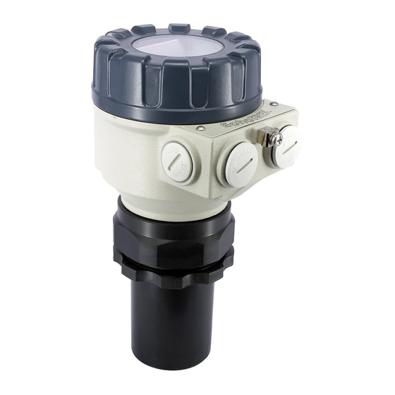
SP-300, SP-300 series
t wo-wire compact ult rasonic
level t ransmit t er
INSTALLATION AND PROGRAMMING MANUAL
2
edition
nd
0 4 0 8
HiTECH/NIVELCO
301 Oxford Valley Road, Bldg 505, Yardley, PA 19067
Tel.: (215) 321-6012 ♦ Fax: (215) 321.6067
Technical support: 888.NIVELCO (888.648-3526)
e-mail:sales@hitechtech.com ♦ http://www.hitechtech.com
♦
BKI 03 ATEX 027X ♦ spa3804a0600p_02
1 / 38
Advertisement
Table of Contents

Related Manuals for NIVELCO EasyTREK SP-300 Series


Summary of Contents for NIVELCO EasyTREK SP-300 Series
- Page 1 INSTALLATION AND PROGRAMMING MANUAL edition 0 4 0 8 HiTECH/NIVELCO 301 Oxford Valley Road, Bldg 505, Yardley, PA 19067 Tel.: (215) 321-6012 ♦ Fax: (215) 321.6067 Technical support: 888.NIVELCO (888.648-3526) e-mail:sales@hitechtech.com ♦ http://www.hitechtech.com ♦ BKI 03 ATEX 027X ♦ spa3804a0600p_02 1 / 38...
- Page 2 Min. measuring distance BASIC CONCEPTS AND ELEMENTS OF ULTRASONIC MEASUREMENT DIST = Distance (measured) LEV = Level (calculated: H-DIST ) VOL = Volume (calculated from LEV) Device data Application data Measurement ♦ 2 / 38 ♦ BKI 03 ATEX 027X spa3804a0600p_02...
-
Page 3: Table Of Contents
CONTENTS 1. INTRODUCTION..................5 5.3.2. Current output ................20 5.3.3. Digital communication ............... 21 2. TECHNICAL DATA ................6 5.3.4. Measurement optimisation ............21 5.3.5. Volume (content) measurement..........25 2.1 General data..................6 5.3.6. Open channel flow measurement ..........26 2.2 Additional data for Ex certified devices………………………………5 5.3.7. -
Page 5: Introduction
A Total beam angle of 5°-7° at –3 dB as is featured by most of HiTECH/Nivelco’s SenSonic transducers ensuring a reliable measurement The EasyTREK compact ultrasonic level transmitters from HITECH/NIVELCO in narrow silos with uneven side walls as well as in process tanks with are excellent tools for level measurement of liquids. -
Page 6: Technical Data
∅6mm x 3m (available max. length 30m) Electrical protection Class III SELV Under optimal circumstances of reflection and stabilised transducer temperature. For pressures below 1 bar representative of Nivelco should be consulted. 2.2 A DDITIONAL DATA FOR EX CERTIFIED DEVICES Ex marking II1G EEx ia IIB T6 IP68 µ... -
Page 7: Special Data
2.3 S PECIAL DATA PP, PVDF PTFE PECIAL DATA FOR TRANSDUCERS ALSO APPLIES TO EX MODELS Type SP -39 SP -38 - SP -37 - SP -36 - SP -34 - Transducer material PP, PVDF PTFE PP, PVDF PTFE PP, PVDF PTFE PP or PVDF PP or PVDF... -
Page 8: Dimensions
2.6 D IMENSIONS EasyTREK EasyTREK EasyTREK EasyTREK EasyTREK SP -39 - / PP, PVDF, SP -38 - / PP, PVDF, SP -37 - / PP, PVDF, SP -36 - / PP, PVDF, SP -34 - / PP, PVDF, PTFE PTFE PTFE PTFE PTFE... -
Page 9: Installation
3. INSTALLATION 3.1 L IQUID EVEL EASUREMENT POSITION The ideal position of the EasyTREK is on the radius r = (0.3 … 0.5) R of the (cylindrical) tank / silo. (Take also sonic cone on page 1 into consideration.) SENSOR ALIGNMENT TEMPERATURE The sensor face has to be parallel to the Make sure that the transmitter is... - Page 10 OBSTACLES WIND Make sure that no objects (cooling pipes, bracing members, Intensive air (gas) movements in the vicinity of the ultrasonic thermometers etc.) protrude into the sensing cone of the ultrasonic cone is to be avoided. A strong draft of wind may "blow away" beam.
-
Page 11: Open Channel Flow Measurement
• Install the unit in a place defined by the characteristics of the metering channel along the longitudinal axis of the flume or weir. In case of Parshall flumes supplied by NIVELCO the location of the sensor is marked. •... -
Page 12: Putting Into Operation
5. PUTTING INTO OPERATION 5.1. U SAGE Subsequent to powering the correctly wired device would start to tick and after 10 - 20 s ECHO LED go on and 4 ... 20 mA signal appears on the current output. Measurement will be according to the factory setting. The factory setting is throughout apt to check proper working and to perform simple measurement tasks but features residing in the unit can only be utilised by adjusting the EasyTREK to the application by programming. -
Page 13: Safety Regulations For Units With Ex Approvals
5.2. S AFETY REGULATION FOR THE X APPROVED UNITS Diameter of the cable should match the cable conduit. The cable outside the unit should be fixed so that it should be free of loading. The terminal box should be selected in accordance with the electrical class of the area. Transmitter can only be powered by certified intrinsically safe current loop. -
Page 14: Programming
- EView software run on the PC connected through HART modem to the loop or - Nivelco made MultiCONT multi-channel process control unit. Since these access methods differ in their form and handling present manual does not review them. The information is contained in the relevant descriptions and user’s manuals. - Page 15 P01: - - 1 a Measurement Mode FACTORY DEFAULT: 11 Parameter value „a” will determine the basic measurement value that will be transmitted. Subsequently values for the relays are also relating to these quantities. Measurement Transmitted value Display symbol mode Distance Distance DIST...
- Page 16 VOL% − VOL%= Transmitted value − (H-DIST) P40…P45 Parameters to set P01(a) P01(a) = P02(b) P02(b) ≥ X ≥ X P40…P45 100% P40…P45 A: Shortest measurable distance B: Volume (content) pertaining to the greatest measurable level C: Whole value of the vessel D: diagram valid for the default value of P10 P11 ♦...
- Page 17 P02: - c b a Calculation units FACTORY DEFAULT: 000 Temperature °C °F This table is interpreted according to P00(c) , P01(a) and P02(c) and is irrelevant in case of percentage measurement [ P01(a)= 2 or 4 )] Volume Weight (set also P32) Volume flow Metric Metric...
- Page 18 P05: - - - - Minimum measuring distance (Dead zone- Close-end blocking) FACTORY DEFAULT: X as per chart The range, beginning with the sensor’s surface, within which (due to the physical restraint of the ultrasound measurement system) measurement can not be made, is called the dead zone. The EasyTREK will not accept any echo within the blocking distance set here. Close end blocking may be represented as the extension of the dead zone within which a possible echo will not be taken into consideration making possible to exclude disturbing objects near to the sensor.
- Page 19 P06: - - - - Far end blocking FACTORY DEFAULT: 0 Far end blocking is the range below the level set in parameter P06 . The far-end blocking can be used to avoid disturbing effect of stirrer or heaters at the bottom of the tanks. Detecting echoes in this range the unit provides special signals.
-
Page 20: Current Output
5.3.2. C URRENT UTPUT P08: - - - - Fixed current output FACTORY DEFAULT: 0 By this step the output current can be set for a fix value selected from between 3,8 mA and 20,5 mA. This function is not operational as per the factory default: 0. -
Page 21: Digital Communication
5.3.3. D IGITAL COMMUNICATION P19: - - - a Short (HART) address of the unit FACTORY DEFAULT : 2 These addresses with 0 … 15 are, in accordance with the HART standard, for distinguishing units in the same loop. • Address: 0 current output of 4 …... - Page 22 P25: - - - a Selection of Echo within the measuring window FACTORY DEFAULT: 0 A so-called measuring window is formed around the echo signal. The position of this measuring window determines the flight time for calculation of the distance to the target. (the picture below can be seen on the test oscilloscope) Received Echo 1.
- Page 23 P28 - - - a Echo loss indication FACTORY DEFAULT: 0 Echo loss indication Remark During short echo-loss (for the period of twice the time set in P20 ) analogue output will hold last value. After this period the current value according to the setting in P12 and via HART ERROR CODE 2 will be transmitted.
- Page 24 P29 - - - - Blocking out of disturbing object FACTORY DEFAULT: 0 One fixed object in the tank, disturbing the measurement, can be blocked out. By the use the Echo Map ( P70 ) the precise distance of disturbing object can be read out.
-
Page 25: Volume (Content) Measurement
5.3.5. V OLUME CONTENT MEASUREMENT P40: - - ba Tank shape FACTORY DEFAULT: Tank shape Also to be set Standing cylindrical tank shape (value of “b” as below) P40 (b), P41 Attention! Standing cylindrical tank with conical bottom P41 , P43 , P44 The value „a”... -
Page 26: Open Channel Flow Measurement
5.3.6. O PEN CHANNEL FLOW MEASUREMENT P40: - - b a Devices, formula, data FACTORY DEFAULT: Devices, formula, data Also to be set Type Formula Qmin [l/s] Qmax [l/s] “P” [cm] GPA-1P1 Q [l/s]= 60.87 * h 1,552 0.26 5.38 GPA-1P2 Q [l/s]= 119.7 * h 1,553... - Page 27 P41-45: Flume/weir dimensions FACTORY DEFAULT: P40=00 . Nivelco Parshall flumes (GPA1P1 … GPA-1P9) For further details see the Manual of the Parshall flume EasyTREK EasyTREK P40=09 General Parshall flume 0.305 < P42 (width) <2.44 ⋅ ⋅ ⋅ 2,5 < P42...
- Page 28 P40= 10 Palmer-Bowlus (D/2) flume /s]= f(h1/ P41 ) * P41 , where h1[m]= h+( P41 /10) P41 [m] D/10 P40= 11 Palmer-Bowlus (D/3) flume /s]= f(h1/ P41 ) * P41 , where h1[m]= h+( P41 /10) P41 [m] D/10 P40= 12 Palmer-Bowlus (rectangular) flume /s]= C * P42 * h...
- Page 29 P40= 13 Khafagi Venturi flume 15cm Q [m /s] = 1,744 P42 h + 0,091 h P42 [m] h [m] EasyTREK EasyTREK P40= 14 P40=14 Bottom step weir 0,0005 < Q [m /s] < 1 0,3 < P42 [m] < 15 0,1 <...
- Page 30 P40= 16 Trapezoidal weir P40=16 0,0032 < Q [m /s] < 82 20 < P41 [°] < 100 0,5 < P42 [m] < 15 0,1 < h [m] < 2 Q [m /s] = 1,772 P42 h + 1,320 tg( P41 /2) h 2,47 Accuracy: ±...
- Page 31 P40= 19 P40=19 THOMSON (90°-notch) weir 0,0002 < Q [m /s] < 1 0,05 < h [m] < 1 /s] = 1,320 h 2,47 Accuracy: ± P40= 20 P40=20 Circular weir 0,0003 < Q [m /s] < 25 0,02 < h [m] < 2 /s] = m * b D , where b = f (h/D) m= 0,555+0,041 h/ P41 +( P41 /(0,11 h))
-
Page 32: 32-Point Linearisation
5.3.7. 32-P OINT LINEARISATION P47: - - - a Linearisation FACTORY DEFAULT: 0 Linearisation is the method of assigning requested (calibrated or calculated) level, volume or flow to values measured by the transmitter. It can be used for instance if the sound velocity is not known (LEVEL⇒LEVEL) or in the case of tank with other shape than under 6.4 or open channel other than under 6.5 (LEVEL ⇒... -
Page 33: Informational Parameters (Read Out Parameters)
5.3.8. I NFORMATIONAL PARAMETERS READ OUT PARAMETERS P60: - - - - Overall operating hours of the unit (h) P61: - - - - Time elapsed after last switch-on (h) P64: - - - - Actual temperature of the transducer (°C/°F) Broken loop of the thermometer will be indicated by display of the Pt Error message initiated by a signal sent via HART. -
Page 34: Additional Parameters For Flow Metering
The need for cleaning of the sensor head may occur. Cleaning should be performed by utmost care where scraping or denting of the transducer have to be avoided. Repair under or after the guarantee period should only be carried out by Nivelco. Devices for repair should only be returned duly cleaned and disinfected. ♦... -
Page 35: Error Codes
7. ERROR CODES Error Error description Causes and solutions Code Memory error Contact local agent No Echo Echo loss See Action 5 and 6 Hardware error Contact local agent Display overflow Check settings Sensor error or improper installation/mounting, level in Verify sensor for correct operation and check for correct mounting the dead band according to the User’s Manual... -
Page 36: Parameter Table
8. PARAMETER TABLE Par. Page Description Value Par. Page Description Value d c b a d c b a Application/Engineering Units Echo loss indication Measurement Mode Blocking out a disturbing object Calculation units – Sound velocity values in different gases Maximum Measuring Distance Specific gravity Minimum Measuring Distance... - Page 37 Page Description Value Description Value Par. Par. Page d c b a d c b a – TOT2 volume flow totalised – – – – – – Overall operating hours of the unit – Time elapsed after last switch-on – –...
-
Page 38: Sound Velocity Values In Different Gases
9. SOUND VELOCITY VALUES IN DIFFERENT GASES The following table contains the sound velocity values of various gases measured at 20°C . Gases Formula Sound Velocity (m/s) Gases Formula Sound Velocity (m/s) 252.8 267,3 Acetaldehyde Ethanol 340.8 329,4 Acetylene Ethylene Ammonia 429,9 Helium...
Need help?
Do you have a question about the EasyTREK SP-300 Series and is the answer not in the manual?
Questions and answers