
Related Manuals for vacuubrand ME 2 NT


Summary of Contents for vacuubrand ME 2 NT
- Page 1 Technology for Vacuum Systems Instructions for use ME 2 NT - ME 4 NT - ME 4S NT MZ 2 NT - MZ 2D NT - MZ 2S NT ME 8 NT - ME 8S NT - MD 4 NT - MD 4S NT - MV 2 NT...
- Page 2 2 of 67 Dear customer, Your VACUUBRAND diaphragm pumps are designed to provide you with many years of trouble-free service with optimal performance. Our many years of practical experience allow us to provide a wealth of application and safety information. Please read these instructions for use before the initial operation of your pump.
- Page 3 page 3 of 67 Achtung: Die vorliegende Betriebsanleitung ist nicht in allen EU-Sprachen verfügbar. Der Anwender darf die beschriebenen Geräte nur dann in Betrieb nehmen, wenn er die vorliegende Anleitung versteht oder eine fachlich korrekte Übersetzung der voll- ständigen Anleitung vorliegen hat. Die Betriebsanleitung muss vor Inbetriebnahme der Geräte vollständig gelesen und verstanden werden, und alle geforderten Maß- nahmen müssen eingehalten werden.
- Page 4 page 4 of 67 Bemærk: Denne manual foreligger ikke på alle EU sprog. Brugeren må ikke be- tjene apparatet hvis manualen ikke er forstået. I det tilfælde skal en teknisk korrekt oversættelse af hele manual stilles til rådighed. Manual skal være gennemlæst og forstået før apparatet betjenes og alle nødvendige forholdsregler skal tages.
- Page 5 page 5 of 67 Figyelem! Ez a kezelési utasítás nem áll rendelkezésre az EU összes nyelvén. Ha a felhasználó nem érti jelen használati utasítás szövegét, nem üzemeltetheti a készüléket. Ez esetben a teljes gépkönyv fordításáról gondoskodni kell. Üzembe helyezés előtt a kezelőnek végig kell olvasnia, meg kell értenie azt, továbbá az üzemeltetéshez szükséges összes mérést el kell végeznie.
- Page 6 page 6 of 67 Attentie: Deze gebruiksaanwijzing is niet in alle talen van de EU verkrijgbaar. De gebruiker moet niet met dit apparaat gaan werken als voor hem/haar de gebruiks- aanwijzing niet voldoende duidelijk is. Bij gebruik van deze apparatuur is het nood- zakelijk een technisch correcte vertaling van de complete gebruiksaanwijzing te hebben.
- Page 7 page 7 of 67 Varning: Denna instruktion är inte tillgänglig på alla språk inom EU. Användaren får inte starta utrustningen om hon/han inte förstår denna instruktion. Om så är fallet måste en tekniskt korrekt instruktion göras tillgänglig. Instruktionen måste läsas och förstås helt före utrustningen tas i drift och nödvändiga åtgärder göres.
-
Page 8: Table Of Contents
page 8 of 67 Contents Safety information! ............. 9 Important information! ................. 9 General information ................11 Intended use..................11 Setting up and installing the equipment ..........12 Ambient conditions ................14 Operating conditions ................. 15 Safety during operation ..............16 Maintenance and repair..............19 Additional safety information for ME 4R NT ........ -
Page 9: Safety Information
Make operating personnel aware of dangers arising from the pump and the pumped substances. VACUUBRAND disclaims any liability for inappropri- ate use of these pumps and for damage from failure to follow instructions contained in this manual. - Page 10 page 10 of 67 ➨ DANGER indicates a hazardous situation which, if not avoided, will result in death or serious injury. + WARNING indicates a hazardous situation which, if not avoided, could result in death or serious injury. • CAUTION indicates a hazardous situation which, if not avoided, could result in minor or moderate injury.
-
Page 11: General Information
page 11 of 67 General information Remove all packing material from the packing box. Re- NOTICE move the product from its packing-box and retain all pack- aging until the equipment is inspected and tested. Re- move the protective caps from the inlet and outlet ports and retain for future use. -
Page 12: Setting Up And Installing The Equipment
page 12 of 67 and +40°C). Periodically check maximum temperatures if installing the pump in a cabinet or a housing. Make sure ventilation is adequate to maintain recommended operating temperature. Install an external automatic ventilation system if necessary. If pumping hot process gases, make sure that the maximum permitted gas in- let temperature is not exceeded. - Page 13 page 13 of 67 + Do not permit any uncontrolled pressurizing. Make sure that the exhaust pipeline cannot become blocked. If there is an exhaust isolation valve, make sure that you cannot operate the equipment with the valve closed to avoid a risk of bursting! + Always provide a free and pressureless exhaust outlet to avoid damage to pump valves and risk of bursting.
-
Page 14: Ambient Conditions
page 14 of 67 Keep a minimum distance of 8 in (20 cm) between the NOTICE cooling fan and surrounding items (e.g., housing, walls, etc.). Check fan regularly for dust/dirt. Clean fan guard grill if necessary to avoid a reduction of ventilation. Use only hoses at the inlet and outlet of the pump with an inner diameter at least as large as the diameter of the pump’s tubing (to avoid overpressure at the outlet, and... -
Page 15: Operating Conditions
page 15 of 67 To the best of our knowledge the equipment is in com- NOTICE pliance with the requirements of the applicable EC-direc- tives and harmonized standards (see ”Declaration of Con- formity”) with regard to design, type and model. Directive EN 61010-1 gives in detail the conditions under which the equipment can be operated safely (see also IP degree of protection, “Technical data”, pg. -
Page 16: Safety During Operation
page 16 of 67 + The pumps are not suitable for pumping dust. Do not pump dust. • Do not pump substances which may form deposits in- side the pump. The pumps are not suitable for pumping substances which may form deposits inside the pump. Deposits and condensate in the pump may lead to in- creased temperatures even to the point of exceeding the maximum permitted temperatures. - Page 17 page 17 of 67 failure, mechanically generated sparks, hot surfaces or static electricity may ignite these mixtures. Use inert gas for venting, if necessary. ➨ Drain appropriately or otherwise remove any potentially explosive mixtures at the outlet of the pump, or dilute them with inert gas to non-explosive concentrations.
- Page 18 page 18 of 67 lead to dangerous conditions. In case of a diaphragm failure or in case of a leak in the manifold, pumped sub- stances might be released into the environment or into the pump housing or motor. Comply with all notes regarding proper use of the pumps, as well as operation and maintenance guidance.
-
Page 19: Maintenance And Repair
For details and for the online ”Instructions for repair” man- ual see www.vacuubrand.com. In case of normal wear, the lifetime of the diaphragms and valves is > 10000 operating hours. Bearings have a typical durability of 40000 h. -
Page 20: Additional Safety Information For Me 4R Nt
page 20 of 67 ➨ Note: The pump may be contaminated with process chemicals, which have been pumped during operation. Ensure that the pump is completely decontaminated before maintenance commences. + Take adequate precautions to protect people from the effects of dangerous substances if contamination has occurred. - Page 21 page 21 of 67 “Use and operation”, pg. 38. Use the equipment only as intended, that is, for genera- NOTICE tion of vacuum or for compression of gases in vessels de- signed for that purpose. Any other use will automatically invalidate all warranty and liability claims.
-
Page 22: Important Information: Equipment Marking (Atex)
The overall category of the equipment depends on the connected com- ponents. If the connected components do not comply with the classifi- cation of the VACUUBRAND equipment, the specified category of the VACUUBRAND equipment is no longer valid. Vacuum pumps and vacuum gauges in category 3 are intended for con- nection to equipment in which during normal operation explosive atmo- spheres caused by gases, vapors or mists normally don’t occur;... - Page 23 page 23 of 67 The pumps are marked with ”X” (according to EN 13463-1), i.e., restric- tions of the operation conditions: • The equipment is designated for a low degree of mechanical stress and has to be installed in a way so that it cannot be damaged from outside.
-
Page 24: Technical Data
page 24 of 67 Technical data General technical data valid for all pumps Permissible ambient temperature °F 14 to 140 / 50 to 104 storage / operation (°C) (-10 to +60 / +10 to +40) Permissible relative atmospheric mois- 30 to 85 ture during operation (no condensation) No-load speed 50/60 Hz 1500 / 1800... - Page 25 page 25 of 67 ME 4 NT Type MZ 2 NT MZ 2S NT ME 4S NT Maximum pumping speed 2.4 / 2.6 1.3 / 1.4 1.2 / 1.4 50/60 Hz (ISO 21360) (4.0 / 4.4) (2.2 / 2.4) (2.0 / 2.3) 52 (70) Torr Ultimate vacuum (absolute)
- Page 26 page 26 of 67 Type MZ 2D NT ME 8 NT ME 8S NT Maximum pumping speed 1.4 / 1.5 4.3 / 4.8 4.2 / 4.6 50/60 Hz (ISO 21360) (2.3 / 2.5) (7.3 / 8.1) (7.1 / 7.8) Torr Ultimate vacuum (absolute) (mbar) (70)
- Page 27 page 27 of 67 Type MD 4S NT MD 4 NT MV 2 NT Maximum pumping speed 2.2 / 2.5 1.3 / 1.4 50/60 Hz (ISO 21360) (3.8 / 4.3) (2.2 / 2.4) Torr 0.75 Ultimate vacuum (absolute) (mbar) (1.0) (0.5) Maximum permissible inlet pressure (absolute)
- Page 28 28 of 67 Type ME 4R NT ME 2 NT Maximum pumping speed 2.2 / 2.5 1.2 / 1.3 50/60 Hz (ISO 21360) (3.8 / 4.2) (2.0 / 2.2) Torr Ultimate vacuum (absolute) (mbar) (100) (70) Maximum permissible inlet...
- Page 29 page 29 of 67 Type MD 4CRL NT Maximum pumping speed 2.0 / 2.2 50/60 Hz (ISO 21360) (3.4 / 3.8) Torr Ultimate vacuum (absolute) (mbar) (1.5) Maximum permissible inlet pressure (absolute) (bar) (1.1) Maximum permissible outlet pressure (absolute) (bar) (1.1) Maximum pressure difference between inlet and outlet...
-
Page 30: Wetted Parts
page 30 of 67 Wetted parts Components Wetted materials aluminum alloy Housing cover (AlMgSi0.5 or AlSi12) Head cover aluminum alloy (AlSi12) Diaphragm clamping disc aluminum alloy (AlSi12) Diaphragm clamping disc (ME 4S NT / ETFE glass fiber reinforced MZ 2S NT / ME 8S NT / MD 4S NT) Diaphragm Diaphragm (ME 4S NT / MZ 2S NT / PTFE... -
Page 31: Abbreviations
page 31 of 67 Components Wetted materials Connection tube PTFE Fittings stainless steel Seal rings Vacuum / pressure adjustment device (ME 4R NT) O-ring Valve block aluminum alloy Seal ring at manometer copper Hollow bolt, dispensing screw stainless steel Overpressure safety relief device We reserve the right for technical modification without prior notice! Abbreviations ETFE: Ethylene/Tetrafluoroethylene... -
Page 32: Pump Parts
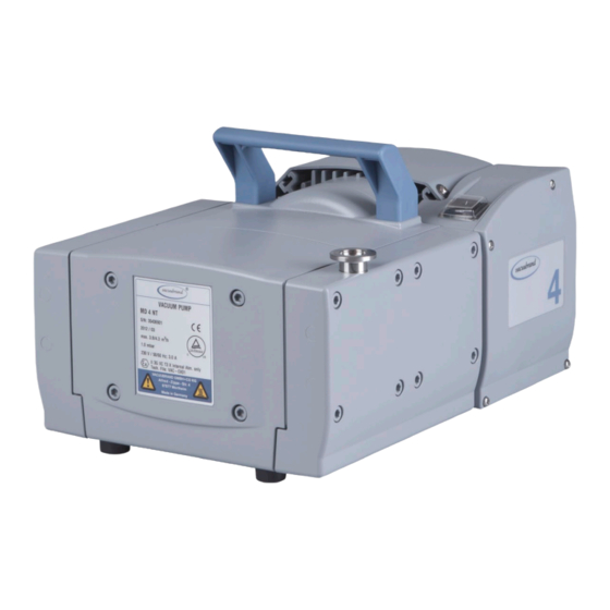
page 32 of 67 Pump parts Position Component Inlet Outlet ON/OFF switch Power connection Handle Pump rating plate Inlet with vacuum adjustment device Outlet with pressure adjustment device Dispensing screw Overpressure manometer Vacuometer Overpressure safety relief device Voltage selection switch We reserve the right for technical modification without prior notice! Power connection (all pump designs) - Page 33 page 33 of 67 ME 4 NT ME 4 NT / ME 4S NT (fig.: ME 4 NT)
- Page 34 page 34 of 67 ME 4R NT MZ 2 NT / MZ 2S NT (fig.: MZ 2 NT)
- Page 35 page 35 of 67 MZ 2D NT ME 8 NT / ME 8S NT...
- Page 36 page 36 of 67 MD 4 NT / MV 2 NT (fig.: MV 2 NT) MD 4 NT MD 4S NT...
- Page 37 page 37 of 67 MD 4CRL NT...
-
Page 38: Use And Operation
page 38 of 67 Use and operation Installing a pump in a vacuum system ➨ If dangerous or polluting fluids could be released at the outlet, install an appropriate system to catch and dis- pose of those fluids. + Connect a gas-tight exhaust line at the pump outlet if necessary. - Page 39 page 39 of 67 • Reduce the transmission of vibration. Prevent mechan- ical load due to rigid pipelines. Insert elastic hoses or flexible elements as couplings between the pump and rigid pipes. Note: Flexible elements will compress or flatten when evacuated if not designed for use under vacuum.
- Page 40 page 40 of 67 Use connecting hoses with large diameter and keep them as short as possible to avoid flow losses. Locate the pump as closely as possible to the application. Always install outlet tubing descending from the pump to avoid backflow of condensate towards the pump.
- Page 41 page 41 of 67 C: Manometer with pressure compensation valve pressure Vent the manometer using the pressure com- compensation pensation valve. Close the valve after ventila- valve tion. + Repeat if necessary until dial shows zero with measuring connection at atmospheric pressure.
-
Page 42: During Operation
page 42 of 67 During operation ➨ Vent and dispose of potentially dangerous gases or vapors at the outlet of the pump appropriately. + Due to the high compression ratio, the pump might gen- erate overpressure at the outlet. Check pressure com- patibility with system components (e.g., exhaust tubing or exhaust valve) at the outlet. - Page 43 page 43 of 67 ME 4R NT: • Note: There are no stops at the end of the dispensing screws’ threads! Do not completely unscrew the dis- pensing screws! Do not start the pump if the pressure difference between NOTICE inlet and outlet ports exceeds max.
-
Page 44: Shutdown & Storage
page 44 of 67 - Turning the dispensing screw counterclockwise: vacu- um is decreased (higher pressure) (Intake of additional bleed air via the dispensing screw.) - Turning the dispensing screw clockwise: vacuum is in- creased (lower pressure) Use the pressure adjustment device at the outlet port of the pump to control the overpressure accordingly: - Turning the dispensing screw counterclockwise: pres- sure is decreased (Pump blows off via dispensing... -
Page 45: Accessories
(Simultaneous operation of two systems at different pressure levels, stainless steel/FFKM, leak rate < 1.6*10-3 Torr*cfm for pressure differences > 375 Torr (500 mbar)) For additional accessories such as vacuum valves, small-flange components, vac- uum gauges or vacuum controllers refer to www.vacuubrand.com... -
Page 46: Troubleshooting
page 46 of 67 Troubleshooting Fault Possible cause Remedy ❑ Pump does not ➨ Electrical power cord ✔ Plug in power cord. start or stops im- not plugged in, electri- Check fuse. mediately. cal supply failure? ➨ Device fuse blown? ✔... - Page 47 page 47 of 67 Fault Possible cause Remedy ❑ Pump too noisy. ➨ Atmospheric or high ✔ Connect hose or silencer pressure at the pump to pump outlet. Be careful inlet? not to cause outlet over- pressure, especially with condensable vapors. ➨...
-
Page 48: Replacing Diaphragms And Valves
page 48 of 67 Replacing diaphragms and valves + Please read section ”Replacing diaphragms and valves” com- pletely before starting maintenance. The pictures may show other versions of pumps. This does not change the method of replacing diaphragms and valves. ➨... - Page 49 - Regular maintenance will improve the lifetime of the pump and also protect both users and the environment. Service kit for ME 2 NT................696877 Service kit for ME 4 NT / MZ 2 NT ..............696860 Service kit for MD 4 NT / MV 2 NT .............696861 Service kit for ME 8 NT ................
-
Page 50: Cleaning And Inspecting The Pump Heads
page 50 of 67 Cleaning and inspecting the pump heads ME 4R NT: ➨ Use an open end wrench (width 17) to re- move the screw-in fitting from the pump head (steady fitting with a second open end wrench width 20), and remove along with the connecting hose. - Page 51 page 51 of 67 View of the disassembled pump head parts MZ 2 NT (fig.: MZ 2 NT, MZ 2D NT and MD 4 NT) MZ 2D NT MD 4 NT Pump head parts: F: Countersunk head screw A: Housing cover G: Diaphragm B: O-rings (not ME 8 NT) H: Diaphragm support disc...
-
Page 52: Replacing The Diaphragm
➨ Disassemble the housing cover (A) to check the valves (C). ➨ Unscrew four (ME 2 NT / ME 4(R, S) NT / MZ 2(D, S) NT) or eight (ME 8 NT / MD 4(S, CRL) NT / MV 2 NT) Allen screws with a 5mm wide Allen key. - Page 53 Henkel Technologies ® ® Replacing the diaphragms of pumps ME 2 NT, ME 4(R, S) NT, MZ 2(S) NT, ME 8 NT, MD 4(S, CRL) NT, MV 2 NT: + Check diaphragm (G) for damage and re- place if necessary.
- Page 54 page 54 of 67 + Too few washers: The pump will not attain vacuum specification. Too many washers: Diaphragm clamping disc will hit head cover, causing noisy operation and possibly causing the pump to seize up. + If the old diaphragm is difficult to separate from the diaphragm support disc, immerse assembly in naphtha or petroleum ether.
-
Page 55: Assembling The Pump Heads
page 55 of 67 Assembling the pump heads ➨ Bring the diaphragms (G) into a position, in which they are in contact with the housing (K) and centered with respect to the bore. ➨ Put on head cover (D). + Pay attention to the correct orientation of the head covers: Align the nib at the head cover (D) with the notch of the housing cover (A). -
Page 56: Assembling Fittings (Me 4(R, S) Nt, Mz 2(D, S) Nt, Md 4Crl Nt)
page 56 of 67 ➨ Screw in the Allen head screws at the head covers diagonally at first slightly with a 5 mm wide Allen key, then tighten. + Recommended torque: 8.9 ft (12 Nm). Assembling fittings (ME 4(R, S) NT, MZ 2(D, S) NT, MD 4CRL NT) ME 4R NT: ➨... - Page 57 page 57 of 67 ME 4(S) NT, MZ 2(D, S) NT MD 4CRL NT ➨ N ote: Always perform a leak test using an appropriate leak detector (e.g., helium leak detector) after opening the pump! Leak rate (integral) see “Technical data”, pg. 24. Replace diaphragms and valves of the opposite side of the pump in the same way! Checking the ultimate vacuum...
-
Page 58: Replacing The Fuse
page 58 of 67 Replacing the fuse ➨ Switch off the pump. ➨ Disconnect the electrical power cord before opening the terminal box. After disconnecting from power, wait two minutes to allow the capacitors to discharge. + The replacing of the fuse has to be carried out by a trained electrician. -
Page 59: Notes On Return To The Factory
page 59 of 67 Notes on return to the factory Repair - return - DAkkS calibration Safety and health of our staff, laws and regulations re- NOTICE garding the handling of dangerous goods, occupational health and safety regulations and regulations regard- ing safe disposal of waste require that for all pumps and other products, the “Health and safety clearance form”, pg. - Page 60 page 60 of 67 We submit repair quotations only on request and always at the customer’s expense. If an order is placed, the costs incurred for problem diagnosis are offset from the costs for repair or from the purchase price, if the customer pre- fers to buy a new product instead of repairing the defec- tive one.
- Page 61 page 61 of 67 Scrapping and waste disposal: Dispose of the equipment and any components removed from it safely in accordance with all local and national safety and environmental requirements. Particular care must be taken with components and waste oil which have been contaminated with dangerous substances from your processes.
-
Page 62: Warranty
62 of 67 Warranty VACUUBRAND shall be liable for insuring that this prod- uct, including any agreed installation, has been free of de- fects at the time of the transfer of risk. VACUUBRAND shall not be liable for the consequences... - Page 63 By our signature below, we acknowledge that we accept liability for any damage caused by providing in- complete or incorrect information and that we shall indemnify VACUUBRAND from any claims as regards damages from third parties. We are aware that as expressed in § 823 BGB (Public Law Code of Ger- many) we are directly liable for injuries or damages suffered by third parties, particularly VACUUBRAND employees occupied with handling/repairing the product.
-
Page 64: Ec Declaration Of Conformity Of The Machinery
Membranvakuumpumpe / Diaphragm vacuum pump / Pompe à membrane: Typ / Type / Type: ME 2 NT / ME 4 NT / ME 4S NT / MZ 2 NT / MZ 2D NT /MZ 2S NT / ME 8 NT / ME 8S NT / MD 4 NT / MD 4S NT / MD 4CRL NT / MV 2 NT Artikelnummer / Order number / Numéro d‘article: 730000, 730002 / 731000, 731001, 731002,... - Page 65 Bevollmächtigter für die Zusammenstellung der technischen Unterlagen / Person authorized to compile the technical file / Personne autorisée à constituer le dossier technique: Dr. J. Dirscherl · VACUUBRAND GMBH + CO KG · Alfred-Zippe-Str. 4 · 97877 Wertheim · Ger- many Wertheim, 25.05.2012...
- Page 66 page 66 of 67 This certificate is only valid for pumps with the respec- tive mark (Licensed Test mark) on the pump rating plate.
- Page 67 Alfred-Zippe-Str. 4 · 97877 Wertheim / Germany T +49 9342 808-0 · F +49 9342 808-5555 info@vacuubrand.com · www.vacuubrand.com VACUUBRAND GMBH + CO KG - Technology for Vacuum Systems - © 2012 VACUUBRAND GMBH + CO KG Printed in Germany Manual-no.: 999155 / 05/25/2012...
Need help?
Do you have a question about the ME 2 NT and is the answer not in the manual?
Questions and answers