
Related Manuals for vacuubrand ME 4C VARIO select


Summary of Contents for vacuubrand ME 4C VARIO select
- Page 1 Speed controlled Chemistry diaphragm pumps ME 4C VARIO select MZ 2C VARIO select MD 4C VARIO select Instructions for use Original instructions EN OI no.: 20901103...
- Page 2 ® (US-Reg.No 3,833,788), VACUUBRAND (US-Reg.No 3,733,388), ® VACUU·VIEW , GREEN VAC (US-Reg.No. 4,924,553), VACUU·PURE ® ® ® (US-Reg No. 5,559,614) and also the shown company logos are registered trademarks of VACUUBRAND GMBH + CO KG in Germany and/or other countries.
- Page 3 page 3 of 76 Achtung: Die vorliegende Betriebsanleitung ist nicht in allen EU-Sprachen verfügbar. Der Anwender darf die beschriebenen Geräte nur dann in Betrieb nehmen, wenn er die vorliegende Anleitung versteht oder eine fachlich korrekte Übersetzung der voll- ständigen Anleitung vorliegen hat. Die Betriebsanleitung muss vor Inbetriebnahme der Geräte vollständig gelesen und verstanden werden, und alle geforderten Maß- nahmen müssen eingehalten werden.
- Page 4 page 4 of 76 Bemærk: Denne manual foreligger ikke på alle EU sprog. Brugeren må ikke be- tjene apparatet hvis manualen ikke er forstået. I det tilfælde skal en teknisk korrekt oversættelse af hele manual stilles til rådighed. Manual skal være gennemlæst og forstået før apparatet betjenes og alle nødvendige forholdsregler skal tages.
- Page 5 page 5 of 76 Figyelem! Ez a kezelési utasítás nem áll rendelkezésre az EU összes nyelvén. Ha a felhasználó nem érti jelen használati utasítás szövegét, nem üzemeltetheti a készüléket. Ez esetben a teljes gépkönyv fordításáról gondoskodni kell. Üzembe helyezés előtt a kezelőnek végig kell olvasnia, meg kell értenie azt, továbbá az üzemeltetéshez szükséges összes mérést el kell végeznie.
- Page 6 page 6 of 76 Attentie: Deze gebruiksaanwijzing is niet in alle talen van de EU verkrijgbaar. De gebruiker moet niet met dit apparaat gaan werken als voor hem/haar de gebruiks- aanwijzing niet voldoende duidelijk is. Bij gebruik van deze apparatuur is het nood- zakelijk een technisch correcte vertaling van de complete gebruiksaanwijzing te hebben.
- Page 7 page 7 of 76 Upozornenie: Tento manuál nie je k dispozícii vo všetkých jazykoch EÚ. Užívateľ nesmie obsluhovať zariadenie, pokiaľ nerozumie tomuto manuálu. V takomto prípa- de musí byť k dispozícii technicky správny preklad celého manuálu. Pred obsluhou zariadenia je potrebné si prečítať celý manuál a porozumieť mu, a musia byť prijaté všetky opatrenia.
- Page 8 page 8 of 76 The document ”Safety information for vacuum equipment” and the instruction for use of the vacuum controller VACUU•SELECT ® are part of this manual! Read the ”Safety information for vacuum equipment” and observe the instructions contained therein! Apart from a short description of the VACUU•SELECT operating pan- ®...
-
Page 9: Table Of Contents
page 9 of 76 Contents Safety information! ............11 Important information! ................11 General information ................13 Intended use..................13 Setting up and installing the equipment ..........14 Ambient conditions ................17 Operating conditions ................. 17 Safety during operation ..............19 Maintenance and repair.............. - Page 10 page 10 of 76...
-
Page 11: Safety Information
Make operating personnel aware of dangers arising from the pump and the pumped substances. VACUUBRAND disclaims any liability for inappropri- ate use of these pumps and for damage from failure to follow instructions contained in this manual. - Page 12 page 12 of 76 ➨ DANGER indicates a hazardous situation which, if not avoided, will result in death or serious injury. ☞ WARNING indicates a hazardous situation which, if not avoided, could result in death or serious injury. • CAUTION indicates a hazardous situation which, if not avoided, could result in minor or moderate injury.
-
Page 13: General Information
page 13 of 76 General information Remove all packing material from the packing box. Re- move the product from its packing-box and retain all pack- aging until the equipment is inspected and tested. Re- move the protective caps from the inlet and outlet ports and retain for future use. -
Page 14: Setting Up And Installing The Equipment
page 14 of 76 ☞ Comply with all notes on correct vacuum and electri- cal connections; see section “Use and operation”, pg. ☞ Do not use the pump to generate pressure. ☞ The pumps are designed for ambient temperatures during operation between +50°F and +104°F (+10°C and +40°C). - Page 15 page 15 of 76 The supply cable may be fitted with a molded Europe- an IEC plug or a plug suitable for your local electrical supply. The cable contains wires color coded as fol- lows: green or green and yellow: ground; blue or white: neutral;...
- Page 16 page 16 of 76 • Avoid overpressure of more than 17.5 psi absolute (1.2 bar absolute) in the event that inert gas is connected to the pump, to the gas ballast or to a venting valve. • Note: Flexible elements will shrink when evacuated. •...
-
Page 17: Ambient Conditions
page 17 of 76 Comply with all applicable and relevant safety require- ments (regulations and guidelines). Implement the re- quired actions and adopt suitable safety measures. Ambient conditions ➨ Do not reach for this product if it has fallen into liquid. There is a risk of deadly electrical shock. - Page 18 page 18 of 76 sive atmospheres. Do not pump potentially explo- sive atmospheres with those pumps. ➨ Pumps bearing the mark on their rating plates ” ” are approved for the pumping of potentially explo- sive atmospheres according to their ATEX classifica- tion imprinted on their rating plate, but they are not approved for operation in potentially explosive at- mospheres (see section “...
-
Page 19: Safety During Operation
page 19 of 76 • Consider interactions and chemical reactions of the pumped media. Ensure that the materials of the pump’s wetted parts are compatible with the pumped substances, see section “Technical data”, pg. 26. When changing the substances pumped, we recom- mend purging the pump with air or inert gas prior to changing the pumped media. - Page 20 page 20 of 76 ☞ Make sure that the exhaust pipeline cannot become blocked. ☞ Attention: At pressures above approximately 810 Torr (1080 mbar) the pressure reading becomes incorrect. The display flashes and a warning message is dis- played. Release pressure immediately! Risk of burst- ing! ☞...
- Page 21 page 21 of 76 • Pumping at high inlet pressure may lead to overpres- sure at the gas ballast valve. Pumped gases or con- densate might be expelled if the valve is open. If an in- ert gas supply is connected to the gas ballast, ensure that its inlet pipeline is not contaminated.
-
Page 22: Maintenance And Repair
For details and for the online ”Instructions for repair” man- ual see www.vacuubrand.com. In normal use, the lifetime of the diaphragms and valves is typically 15,000 operating hours. Bearings have a typical durability of 40000 h. - Page 23 page 23 of 76 occurred. Use appropriate protective clothing, safety goggles and protective gloves. ☞ Wear parts have to be replaced regularly. ☞ Never operate a defective or damaged pump. ☞ Vent the pump before starting maintenance. Isolate the pump and other components from the vacuum system. Allow sufficient cooling of the pump.
-
Page 24: Important Information: Equipment Marking (Atex)
Important information: Equipment marking (ATEX) Only valid for products with ATEX marking. If the ATEX marking is shown on the rating plate of the respective product, VACUUBRAND GMBH + CO KG assures, that the device complies with the provi- sions of the directive 2014/34/EU. The applied harmonized stand- ards are indicated in the EC Declaration of Conformity of the Ma- chinery (see instructions for use). - Page 25 page 25 of 76 • The equipment is designated for a low degree of mechanical stress and has to be installed in a way so that it cannot be damaged from outside. Pumping units have to be installed so that they are protected against shocks from the outside and against glass splinters in the event of breakage (implosion).
-
Page 26: Technical Data
page 26 of 76 Technical data General technical data valid for all pumps ATEX approval if the ATEX marking II 3/- G Ex h IIC T3 Gc X is shown on the rating plate Internal Atm. only Inner part (pumped gases) Tech.File: VAC-EX02 Maximum permissible inlet pressure (absolute) -
Page 27: Gas Inlet Temperatures
page 27 of 76 Gas inlet temperatures Permitted range of gas Operating condition Inlet pressure temperatures at inlet ➨ 50 °F to 104 °F > 75 Torr (100 mbar) Continuous operation (high gas load) (+10 °C to +40 °C) ➨ 32 °F to 140 °F* <... - Page 28 page 28 of 76 VACUU•SELECT Controller with VACUU•SELECT Sensor VACUU•SELECT Sensor; external gauge head, capacitive, Pressure transducer ceramic diaphragm (alumina), absolute pressure, gas type independent Display color display with touchscreen Pressure units / scale (selectable) Torr, mbar or hPa Measuring range (absolute) 810 - 0.1 Torr (1080 - 0.1 mbar) Maximum control range (absolute)* 810 - 0.1 Torr (1080 - 0.1 mbar)
- Page 29 page 29 of 76 VACUU•SELECT Controller with VACUU•SELECT Sensor Plug-in connector VACUU • BUS Supply voltage (via VACUU • BUS) 24 VDC Device fuse on circuit board Nano fuse 4 A/t Max. power of controller Power sensor 0.2 W Max. switching current (24V / VACUU •...
-
Page 30: Wetted Parts
Pump Head cover ETFE carbon fiber reinforced Diaphragm clamping disc ETFE carbon fiber reinforced Diaphragm PTFE Valves FFKM (ME 4C VARIO select: PTFE) O-rings Valve head ECTFE carbon fiber reinforced Gas ballast tube, inlet, outlet PTFE carbon reinforced Tubing PTFE... -
Page 31: Pump Parts
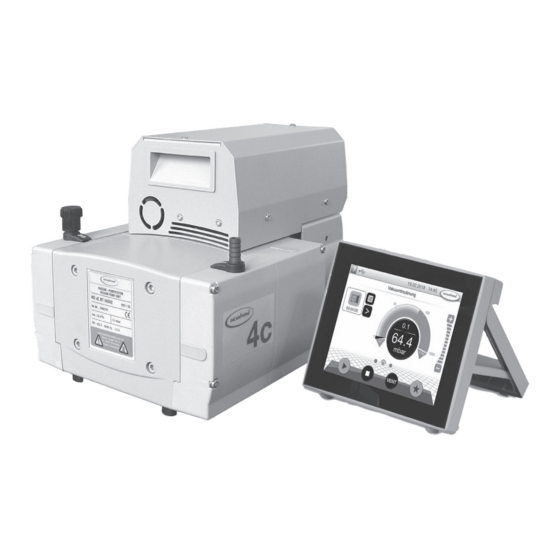
1 Diaphragm pump VARIO select 2 Fan 3 Recessed grip 4 Pump rating plate 5 Inlet 6 Gas ballast valve VACUU•SELECT controller 8 Mains connection 9 ON/OFF switch 10 Outlet (silencer) 11 Fuse holder VACUU•BUS cable to controller ME 4C VARIO select... - Page 32 page 32 of 76 MZ 2C VARIO select MD 4C VARIO select...
- Page 33 page 33 of 76 VACUU•SELECT controller (operating panel and sensor) Component 13 Touchscreen of operating panel 14 Stand (extended) VACUU•SELECT sensor with connection options...
-
Page 34: Vacuu•Select Parts
page 34 of 76 VACUU•SELECT parts Component 1 ON/OFF button 2 Cover of USB port, type A* 3 Screen 4 Chemically resistant plastic housing 5 Rubber feet 3x connection sockets for VACUU•BUS components ® 7 Recess for VACUU•SELECT Sensor ® Power supply via VACUU•BUS ®... - Page 35 page 35 of 76 Operating panel (Top view / Front view / Rear view)
- Page 36 page 36 of 76 Operating panel (Side view) (extending the stand) VACUU•SELECT Sensor (Side view / Top view) Component 1 VACUU•SELECT Sensor 2 VACUU•BUS plug attachment, detachable (option) 3 Venting valve connection 4 Vacuum screw connection 5 Port for VACUU•BUS® plug attachment (park position) 6 Hole for screws VACUU•BUS port...
-
Page 37: Use And Operation
page 37 of 76 Use and operation Apart from a short description of the VACUU•SELECT operating panel, ® this manual describes the mechanical structure of the diaphragm pump. Operation of the VACUU•SELECT vacuum controller and its func- ® tions are described in the separate VACUU•SELECT manual. - Page 38 page 38 of 76 • Reduce the transmission of vibration. Prevent mechan- ical load due to rigid pipelines. Insert elastic hoses or flexible elements as couplings between the pump and rigid pipes. Note: Flexible elements will compress or flatten when evacuated if not designed for use under vacuum.
- Page 39 page 39 of 76 When assembling, ensure vacuum-tightness. After as- sembly, check the whole system for leaks. Secure hose connections at the pump appropriately, e.g., with hose clamps, to protect against accidental detach- ment. To reduce pump noise emanating from the pump exhaust port, connect an exhaust hose or use a silencer (see “Ac- cessories”, pg.
-
Page 40: Vacuu•Select Controller
(e.g., VACUU•SELECT Sensor, etc.) has to be connected to the operating panel. The VACUU•SELECT Controller can only be operated with components compatible with the VACUUBRAND VACUU•BUS system, (see “Accessories”, pg. 52). The vacuum controller controls VACUUBRAND VARIO diaphragm pumps and optional coolant and venting valves. - Page 41 page 41 of 76 Connect the VACUU•SELECT Sensor via hose or small flange connection to the vacuum application. Do not mount the sensor directly at the pump but close to the applica- tion. The cross-section of the tubing should be as large as possible.
- Page 42 page 42 of 76 Operating panel - Process screen Description 1 Status bar 2 Analogue pressure display – pressure curve Digital pressure display – pressure value (target value, actual value, pressure unit) 4 Process screen with context features 5 Screen navigation 6 Operating elements for control Operating panel - Operating elements Button...
- Page 43 page 43 of 76 Operating panel - Operation (➨ see manual of VACUU•SELECT Controller) Start the pump / process: Stop the pump / process: Venting:...
- Page 44 page 44 of 76 During operation ➨ Vent and dispose of potentially dangerous gases or vapors at the outlet of the pump appropriately. ☞ Due to the high compression ratio, the pump might generate overpressure at the outlet. Check pressure compatibility with system components (e.g., exhaust tubing or exhaust valve) at the outlet.
-
Page 45: Important Notes Regarding The Use Of Gas Ballast
page 45 of 76 Check the pump regularly for external soiling and depos- its. Clean the pump if necessary to avoid an increase of the pump’s operating temperature. Operation with silencer (optional) at the outlet: Operating the pump at a high inlet pressure or pumping dusty gases for a long time may cause clogging of the silencer. - Page 46 page 46 of 76 This constitutes a risk of significant damage to equip- ment and/or facilities, a risk of personal injury or even loss of life. ☞ Make sure that air/gas intake through the gas ballast valve can never lead to hazardous, explosive or oth- erwise dangerous mixtures.
-
Page 47: Shutdown & Storage
page 47 of 76 Shutdown & storage The pump can be switched off under vacuum. Short-term: Has the pump been exposed to condensate? - Allow the pump to continue to run at atmospheric pres- sure for a few minutes. Has the pump been exposed to media which may damage the pump materials or form deposits? - Check and clean pump heads if necessary. -
Page 48: Readjustment Of Vacuum Sensor
page 48 of 76 Readjustment of vacuum sensor The device was adjusted using factory standards, which are traceable through regular calibration in an accredited laboratory (DAkkS calibration laboratory) to the German national pressure standard. Depending on the process and/or accuracy requirements, check the adjustment and readjust if necessary. - Page 49 page 49 of 76 Note: Adjustment under vacuum with an actual pressure higher than 0.1 Torr (mbar) reduces the accuracy of the measurement. If the pressure is significantly higher than 0.1 Torr (mbar), adjustment to a reference pressure is rec- ommended.
-
Page 50: Calibration In The Factory
50 of 76 Calibration in the factory Control of measuring equipment The VACUUBRAND DAkkS calibration laboratory is accredited by the Deutsche Akkreditierungsstelle GmbH (national accreditation body of the Federal Republic of Germany) for the measurable variable pressure in the pressure range from 7.5*10... -
Page 51: Cleaning The Pressure Transducer
page 51 of 76 Cleaning the pressure transducer Attention: Never use a pointed or sharp-edged tool to clean the pressure transducer. Never touch the ceramic diaphragm of the pressure transducer with hard objects. - Fill the measurement chamber with a solvent (e.g., benzene) and allow sufficient cleaning time. -
Page 52: Accessories
........20636002 Small flange KF DN 16, for assembly directly at the valve head ....20699918 (at inlet of ME 4C VARIO select / MD 4C VARIO select; at outlet of ME 4C VARIO select / MZ 2C VARIO select) Small flange KF DN 16, for assembly directly at the valve head ....20699919 (at outlet of MD 4C VARIO select) Adapter to PTFE tubing**, for assembly directly at the valve head ...20636274... - Page 53 Please contact VACUUBRAND for further ® information. Listed modules are designed for surface-mounted installation. Different catalog numbers are used for modules designed for flush-mounting with concealed tubing. For additional accessories such as vacuum valves, small-flange components, vacuum gauges or vacuum controllers refer to www.vacuubrand.com.
-
Page 54: Troubleshooting
page 54 of 76 Troubleshooting ➨ See also section „ Error - Cause - Remedy“ in the manual of the VACUU•SELECT vacuum controller Fault Possible cause Remedy ❑ Readings deviate ➨ Vacuum sensor dirty. ✔ Clean sensor measuring from the reference chamber. - Page 55 page 55 of 76 Fault Possible cause Remedy ❑ Vacuum pump ➨ VACUU•BUS plug-in ✔ Check VACUU•BUS plug- does not start. connection or cables in connection and cables defective or not con- to the controller. nected. ➨ Motor overloaded. ✔ Allow the motor to cool Thermal protection has down.
- Page 56 page 56 of 76 Fault Possible cause Remedy ❑ No display. ➨ VACUU•BUS plug-in ✔ Check VACUU•BUS plug- connection or cables in connection and cables defective or not con- to the controller. nected. ➨ Controller switched off. ✔ Switch on controller. ➨...
-
Page 57: Replacing Diaphragms And Valves
page 57 of 76 Replacing diaphragms and valves ☞ Please read section ”Replacing diaphragms and valves” com- pletely before starting maintenance. The pictures may show other versions of pumps. This does not change the method of replacing diaphragms and valves. ➨... -
Page 58: Cleaning And Inspecting The Pump Heads
- Regular maintenance will improve the lifetime of the pump and also protect both users and the environment. Service kit for ME 4C VARIO select ............20696864 Service kit for MZ 2C VARIO select ............20696869 Service kit for MD 4C VARIO select ............20696870 Diaphragm key (width 66 mm) ..............20636554... - Page 59 ☞ Service only one side of the pump at a time to avoid the mixing of parts. Fittings and tubing of the different pump models: ME 4C VARIO select MZ 2C VARIO select MD 4C VARIO select...
- Page 60 page 60 of 76 View of the disassembled pump head parts (fig.: MD 4C VARIO select) A: Head alignment pin / mark L: Fillister head screw B: Connecting rod M: O-ring C: Housing N: Valve D: Washer O: Valve head E: Diaphragm support disc P: Hose nozzle F: Diaphragm...
-
Page 61: Replacing The Diaphragm
page 61 of 76 ➨ For maintenance, lay the pump on its side with the pump heads to be maintained at the top. Support the pump appropriately. ➨ Remove the 4 screws affixing the head cov- er cowling (W) with a Torx driver T20. Pay attention to the washers under the screws and remove. - Page 62 page 62 of 76 ☞ Check diaphragm (F) for damage and re- place if necessary. ➨ Lift diaphragm carefully sidewise. ☞ Never use a pointed or sharp-edged tool to lift the diaphragm. ➨ Use the diaphragm key to grip the diaphragm support disc (E) below the diaphragm.
-
Page 63: Replacing The Valves
page 63 of 76 ☞ Assemble the original number of washers (D) between diaphragm support disc (E) and connecting rod (B). ➨ Screw diaphragm clamping disc (G), dia- phragm (F), diaphragm support disc (E), and washers (D) to connecting rod (B). ➨... - Page 64 page 64 of 76 ➨ Remove valve heads (O) along with the disc springs (R), connection tube if applicable, hose nozzles (P) and connection fasten- ers (Q) or move the valve heads carefully aside. Note position and orientation of the valve heads.
- Page 65 page 65 of 76 ➨ Position clamping bracket (S) with counter- sunk bores facing upwards. ➨ Align the countersunk bores with the thread- ed pegs. ➨ Loosely fasten the countersunk screws and correct the alignment of the valve heads if necessary.
- Page 66 page 66 of 76 ➨ Put head cover cowling on. ➨ Slide the head cover cowling in the grooves of the caps (I) and under the connection fasteners (Q). ➨ Install the washers. Use a Torx driver T20 to attach the 4 screws holding the head cover cowling.
-
Page 67: Replacing The Device Fuse
page 67 of 76 Replacing the device fuse ➨ Switch off the pump. ➨ Disconnect the electrical power cord before un- screwing the fuse holder. Identify and eliminate the cause of failure before switch- ing on the pump again. fuse holder ➨... -
Page 68: Repair - Maintenance - Return - Calibration
3 or 4. These devices cannot be checked, maintained or re- paired. Also decontaminated devices must not returned to VACUUBRAND due to a residual risk.. The same conditions apply to on-site work. No repair, maintenance, return or calibration is possi- ble unless the correctly completed health and safety clearance form is returned. - Page 69 page 69 of 76 If you do not wish a repair on the basis of our quotation, the device may be returned to you disassembled and at your expense. In many cases, the components must be cleaned in the factory prior to repair. For cleaning we use an environmentally friendly water based process.
-
Page 70: Warranty
70 of 76 Warranty VACUUBRAND shall be liable for insuring that this prod- uct, including any agreed installation, has been free of de- fects at the time of the transfer of risk. VACUUBRAND shall not be liable for the consequences... -
Page 71: Declarations And Certificates
Hersteller / Manufacturer / Fabricant: VACUUBRAND GMBH + CO KG VACUUBRAND GMBH + CO KG · Alfred-Zippe-Str. 4 · 97877 Wertheim · Germany Hiermit erklärt der Hersteller, dass das Gerät konform ist mit den Bestimmungen der Richtlinien: Hereby the manufacturer declares that the device is in conformity with the directives: Par la présente, le fabricant déclare, que le dispositif est conforme aux directives:... - Page 72 Manufacturer: VACUUBRAND GMBH + CO KG VACUUBRAND GMBH + CO KG · Alfred-Zippe-Str. 4 · 97877 Wertheim · Germany Hereby the manufacturer declares that the device is in conformity with the directives: Supply of Machinery (Safety) Regulations 2008 (S.I. 2008 No. 1597, as amended by S.I. 2019 No. 696) ƒ...
- Page 73 page 73 of 76 – a “Product Conformity Assessment” (PCA) procedure was performed. As defined in GB/T 26572 the “Maximum Con- centration Value” limits (MCV) apply t • • • • • • ous environmental pollution, cause serious bodily injury or damage to the user’s assets. 有毒有害物质或元素...
- Page 74 page 74 of 76 表示该有毒有害物质在该部件所有均质材料中的含量均在GB/T 26572规定的限量要求以下。 表示该有毒有害物质至少在该部件某一均质材料中的含量超出GB/T 26572规定的限量要求。 电池、玻璃器皿和配件可能不属于所附设备所包含的内容,它们可能有各自单独的EFUP标记和/或可能正在维 护其部件EFUP标记的更新。 除上表所示信息外,还需声明的是,这些部件并非是有意用铅( )、 汞 ( )、铬( )、六价铬 ( )、多溴联苯( )或多溴二苯醚( )来制造的。 –...
- Page 75 page 75 of 76...
- Page 76 Seitenzahl VACUUBRAND > Support > Manuals Manufacturer: VACUUBRAND GMBH + CO KG VACUUBRAND GMBH + CO KG Alfred-Zippe-Str. 4 Alfred-Zippe-Str. 4 97877 Wertheim 97877 Wertheim GERMANY GERMANY Phone: Head office +49 9342 808-0 Sales +49 9342 808-5550 Service +49 9342 808-5660...
Need help?
Do you have a question about the ME 4C VARIO select and is the answer not in the manual?
Questions and answers