Sign In
Upload
Manuals
Brands
Union Instruments Manuals
Measuring Instruments
CWD3000 EXP
Union Instruments CWD3000 EXP Manuals
Manuals and User Guides for Union Instruments CWD3000 EXP. We have
1
Union Instruments CWD3000 EXP manual available for free PDF download: Operating Instructions Manual
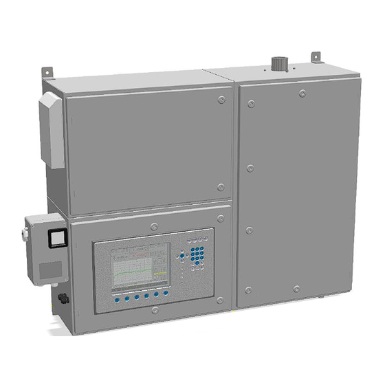
Union Instruments CWD3000 EXP Operating Instructions Manual (120 pages)
Explosion-Protected Combustion Calorimeter
Brand:
Union Instruments
| Category:
Measuring Instruments
| Size: 1 MB
Table of Contents
Table of Contents
3
1 Technical Data
5
Name Plate
5
Fig. 1.1: Name Plate (Example)
5
Dimensions
6
Fig. 1.2: Housing Dimensions
6
Device Overview
7
Explosion Marking as Per EC Type Examination
7
Marking as Per the Iecex Scheme
7
Voltage Supply
7
Fig. 1.3: Markings and Warning Information
7
Interfaces
8
Heating Value Measurement Display Times
8
Gas Inputs
8
Process Gas, Calibration Gas and Test Gas
8
Ignition Protection Gas
8
Combustion Gas
10
Linearity and Measuring Ranges
10
Fig. 1.4: Measuring Ranges and Accuracy
11
Ambient Conditions of Installation Location
12
2 EU Declaration of Conformity
13
3 Safety Instructions
15
Warning Information and Symbols
15
Principle, Intended Use
16
Other Applicable Operating Instructions
16
Additional Information
16
Personnel and Qualification
17
Safety Instructions
18
General Safety Instructions
18
Information on Specific Hazards
18
Recurring Operator Training
18
Information on Explosion Protection
19
Owner Safety Precautions
19
Performing a Workplace Risk Assessment
20
4 Protective Equipment
21
Pressurized Enclosure Ignition Protection Type
21
Protective Housing with Doors
22
Monitoring of the Flushing Process and Overpressure of Flushing System
22
Cable Bushings
22
Fig. 4.1: Housing, Rooms with Lockable Doors
22
Fig. 4.2: Depiction of Control Unit for Pre-Flushing and Overpressure (Example)
22
Thermal Cutoff
23
Solenoid Valve
23
Fig. 4.3: Depiction of Combustion Gas Inlet Solenoid Valves (Example)
23
Pressure Switches
24
Fig. 4.4: Depiction of Pressure Switches (Example)
24
Markings and Warning Information
25
Fig. 4.5: Markings and Warning Information (Example)
25
Fig. 4.6: Warning Information on Electrical Connection Plate (Example) Interior, Cell
26
Fig. 4.7: Name Plate with ATEX/IECEX Marking (Example)
26
5 Description and Connections
27
External Overview and Housing Connections
27
Fig. 5.1: Device Overview
27
Interior Connections and Components
28
Fig. 5.2: Housing with no Doors (Example Showing Carrier Gas Option)
28
Accessories
29
6 Transport, Installation and Acceptance
31
Transport
31
Environmental Conditions
33
Storage Conditions
33
Installing and Connecting
34
Installation Location
35
Wall Mounting
36
Fig. 6.1: Wall Mounting
36
Gas Connections
37
Fig. 6.2: Ignition Protection Gas Connection, Compressed Air, 6 MM Screw Fitting
38
Fig. 6.3: Connections for Process, Calibration, Carrier and Test Gases, 6 MM Screw Fitting
40
Fig. 6.4: Flue Gas/Exhaust Air Connection
41
Opening and Closing of the Housing Doors
42
Electrical Connection
43
Fig. 6.5: Electrical Connection, Control Unit (Example)
44
Voltage Supply
44
Electrical Interfaces
46
Fig. 6.6: Disconnector Unit Gönnheimer FS852, Example
46
Connector Assignment for Input/Output Signals
47
Fig. 6.7: Connector Assignment of Input/Output IO External Type 06
47
Removing/Attaching Transport Securing Devices
50
Fig. 6.8: Transport Securing Devices (Example Shown)
50
Fig. 6.9: Transport Securing Devices of Pressure Controller
51
Owner Safety Precautions
52
Documentation
52
7 Commissioning/Switching on
53
8 Description of the Work Stations/Operator Control Elements
55
Fig. 8.1: Work Stations (Example)
55
9 Operation
57
Operation of Membrane Keyboard/Description of Display
57
Fig. 9.1: Operator Control Elements/Structure of Display
57
Basic Operation
59
Available Displays
59
General Information
60
Fig. 9.2: General Information
60
Fig. 9.3: Information on Overpressure Differential Pressure
61
9.5 Menu Structure
63
Menu Structure
63
Main Menu
64
Main Menu - Options
65
Main Menu - Options - I/O
66
Main Menu - Options - I/O - Analog Outputs
67
Main Menu - Options - I/O - Digital Outputs
68
Main Menu - Options - I/O - Ma Display
70
Main Menu - Options - I/O - Digital Inputs
71
Main Menu - Options - I/O - Display
72
Main Menu - Options - Calibration
73
Main Menu - Options - Calibration - Configuration of Calibration Gas
74
Main Menu - Options - Calibration - Automatic Calibration
75
Main Menu - Options - Calibration - Automatic Calibration 2
76
Main Menu - Options - Calibration - Calibration
76
Main Menu - Options - Calibration - Save Base Calibration
76
Main Menu - Options - Calibration - Calibration Limits
77
Main Menu - Options - System
78
Main Menu - Options - System - General
79
Main Menu - Options - System - Ignition
81
Main Menu - Options - System - Update
81
Main Menu - Options - System - CSV Export
82
Main Menu - Options - System - Hold Signal On/Off
82
Main Menu - Options - System - Load Factory Settings
82
Main Menu - Options - System - Settings
83
Main Menu - Options - System - Settings - Date/Time
83
Main Menu - Options - System - Settings - Language
84
Main Menu - Options - System - Settings - Password
85
Main Menu - Options - System - Settings - Change Color
86
Main Menu - Options - System - Settings - Hardware 1
87
Main Menu - Options - Service
88
Main Menu - Trend
89
Main Menu - Graphic - Select Time
90
Main Menu - Graphic - Select Value
91
Main Menu - Graphic - Select Signal
92
Main Menu - Graphic - Select Unit
92
Main Menu - Graphic - Select Curve
93
Main Menu - Event List
94
Main Menu - Device Information
96
10 Decommissioning/Switching off
97
11 Maintenance
99
Preparations
99
Maintenance/Inspection
100
Cleaning the Surface and Display
101
12 Troubleshooting
105
Preparations for Troubleshooting
106
Changing/Replacing Fuses
107
Changing/Replacing the Battery
107
Unstable Measured Value
107
Drift of Measured Value
107
Faulty Ignition
107
Error/Status Messages
108
13 Service
111
14 Disposal
113
15 Spare Parts
115
16 Appendix
117
Profibus Data Structure
117
Table 1: Profibus Data Structure
117
Serial Interface RS 232 Data Structure (Optional)
118
Index
119
Figures
120
List of Tables
120
Advertisement
Advertisement
Related Products
Union Instruments CWD2005 Plus
Union Instruments CWD 2005
Union Instruments CWD2000 EX
Union Instruments CWD
Union Instruments CWD Plus
Union Instruments CWD2005 SPC
Union Instruments INCA 1000
Union Instruments INCA 2000
Union Instruments INCA 3000
Union Instruments INCA 4000
Union Instruments Categories
Measuring Instruments
Accessories
Control Systems
More Union Instruments Manuals
Login
Sign In
OR
Sign in with Facebook
Sign in with Google
Upload manual
Upload from disk
Upload from URL