
Related Manuals for Pfeiffer Vacuum MVP 040-2


Summary of Contents for Pfeiffer Vacuum MVP 040-2
- Page 1 Betriebsanleitung • Operating Instructions Translation of the Original Operating Instructions Diaphragm Pumps MVP 040-2, MVP 070-3/3C...
-
Page 2: Table Of Contents
Table of contents Table of contents About this manual ........3 Validity. -
Page 3: About This Manual
1 About this manual 1.1 Validity This operating manual is for customers of Pfeiffer Vacuum. It describes the func- tioning of the designated product and provides the most important information for safe use of the unit. The description follows applicable EU guidelines. All informa- tion provided in this operating manual refer to the current state of the product's de- velopment. -
Page 4: Safety
Safety Pictograph Prohibition of an action or activity in connection with a definitions source of danger, the disregarding of which may result in serious accidents. Warning of a displayed source of danger in connection with operation of the unit or equipment. Command to perform an action or task associated with a source of danger, the disregarding of which may result in serious accidents. -
Page 5: Proper Use
• Installation, operating and maintenance regulations must be complied with. • Other accessories than those described in this manual must not be used without the agreement of Pfeiffer Vacuum. • When pumping gases which could form explosive or ignitable mixtures, take suitable precautions: –... -
Page 6: Transport And Storage
Transport and storage 3 Transport and storage 3.1 Transport Î Remove the locking cap from the vacuum and fore-vacuum flange immediately before connecting! Î Use only the handles provided for that purpose to lift the pump. – Do not use the interhead connections on the top side of the pump to carry the pump. -
Page 7: Product Description
Product description 4 Product description 4.1 Product identification To correctly identify the product when communicating with Pfeiffer Vacuum, al- ways have the information from the rating plate available. • Pump model and model number • Serial number • Date of manufacture Scope of delivery •... -
Page 8: Function
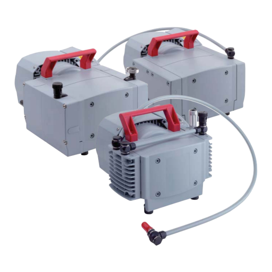
The diaphragm vacuum pumps of the series MVP 070-3 are three stage and those of the MVP 040-2 series are two stage, dry compressor vacuum pumps. The pumps are positive displacement pumps with a periodic change of size of the suction chamber produced by the movement of the diaphragm. - Page 9 Product description Vacuum connection Exhaust Power switch Voltage selector switch Gas ballast valve Fig. 4: MVP 070-3C...
-
Page 10: Installation
Installation 5 Installation 5.1 Setting up the pump Installation location Observe the following requirements when setting up the pump: • Note the load-bearing capacity of the mounting surface. • Maximum installation altitude 2000 m (above mean sea level) • Permissible ambient temperature: +12 ... 40°C •... -
Page 11: Connecting To The Mains Power Supply
Installation WARNING Emission of toxic substances from the exhaust! Danger of poisoning from emitted gases or vapours, which can be detrimental to health and/or can pollute the environment, depending on the particular application. Î Comply with the applicable regulations when working with toxic substances. Î... - Page 12 Installation Single phase motors Î The mains voltage must be determined on-site each time before the pump is in- stalled or moved to a different location. NOTE Overvoltage! An incorrect voltage range setting can damage the motor. Î Disconnect the pump from the power supply. Î...
-
Page 13: Operation
Operation 6 Operation 6.1 Before switching on the pump Î Compare the voltage information on the rating plate with the mains voltage. Î Check that the exhaust connection allows free flow (max. permissible pressure 1.1 bar absolute). – Activate the shut-off valves in such a way that they open before or at the same time as the pump is started. -
Page 14: Pumping Condensable Vapours
Operation 6.3 Pumping condensable vapours Should the process gases contain condensable gases present at high percentages, the vacuum pump must be operated with a gas ballast (i.e. with an open gas ballast valve). WARNING Reactive, explosive or otherwise dangerous mixtures! Uncontrolled gas inlet at the gas ballast valve can result in dangerous mixtures. -
Page 15: Maintenance
Î Re-assemble pump in reverse order. NOTE Service work should be carried out by qualified personal only! Pfeiffer Vacuum is not liable for any damage to the pump resulting from work carried out improperly. Î Take advantage of our service training programs; additional information at www.pfeiffer-vacuum.net. -
Page 16: Cleaning And Replacing Diaphragm And Valves
Checklist for inspec- Certain repair and overhaul work should only be performed by Pfeiffer Vacuum Service (PV). Pfeiffer Vacuum will be released from all warranty and liability claims tion, maintenance if the required intervals for inspection, maintenance, or overhaul are exceeded or... - Page 17 Maintenance 40 A1 2.3 K1 10 3 16 K2 G2 26 Fig. 7: MVP 040-2 Vacuum connection with Silencer Inlet and outlet valve compression coupling in G Sealing ring seal 1/4" Diaphragm spring was- Countersink screw Spacer disks Countersink screw...
- Page 18 Maintenance Î First gently and then firmly tighten diagonally-offset cheesehead screws26; torque: 12 Nm. NOTE Dissimilar valves! Pump not achieving the specified end pressure Î Make sure the valves have the correct mounting orientation; the outlet valve in head cover K1 and the inlet valve in head cover K2 are from PTFE (white). The two other valves are from FPM (brown).
- Page 19 Maintenance MVP 070-3 Cleaning and repla-cing the valves Î Turn off the vacuum pump, vent to atmospheric pressure and allow to cool, if necessary. Î Disconnect the drive motor from the mains and secure it so that it cannot be switched on.
- Page 20 Maintenance Changing the Diaphragm Attach the diaphragm key Î Carefully raise the diaphragm at the side without causing it any damage; do not use sharp-edged tools. Î Slide diaphragm key under the diaphragm until it reaches the support disk. Î Use the diaphragm key to loosen the diaphragm support disk and unscrew to- gether with diaphragm and diaphragm spring washer.
- Page 21 Maintenance 1 ... 4 Diaphragm heads Nose on head cover Valve seal Fig. 10: Positions required for installing the valve seals 11...
- Page 22 Maintenance MVP 070-3C Cleaning and repla-cing the valves Service the pump heads of only one pump side at the same time. Î Turn off the vacuum pump, vent to atmospheric pressure and allow to cool, if necessary. Î Disconnect the drive motor from the mains and secure it so that it cannot be switched on.
- Page 23 Maintenance Loosen clamping claws Î Using a TX20 torx screwdriver, undo two countersunk screws on each side and on the valve heads remove the clamping claws; – the head covers remain assembled. Î Completely remove valve heads together with disc springs, where applicable with connecting hose, hose clips and connection holders;...
- Page 24 Maintenance Changing the Diaphragm Attach the diaphragm key Î Loosen U-hose connection (hose connection to the opposite side of the pump); – do this by levering out the hose clamp with a flat-blade screwdriver and re- moving the hose. Î Undo 4 cylinder screws from the two head covers K and remove both head co- vers together with the valve heads and connections.
-
Page 25: Replacing The Device Fuses
Maintenance 7.3 Replacing the device fuses The safety fuses (PU E22 016 -T) are located in the terminal box and are integrated into a cable. WARNING Voltage-bearing elements Danger to life from electric shock. Î The fuses can be changed only by trained and authorised electricians. Î... -
Page 26: Decommissioning
Decommissioning 8 Decommissioning 8.1 Shutting down for longer periods Before shutting down the pump, observe the following procedure and adequately protect the pump system against corrosion: Shortly after conden- Î Let the vacuum pump continue to run for several minutes with the intake port open. -
Page 27: Malfunctions
Malfunctions 9 Malfunctions Please note the following instructions should the pump malfunction: CAUTION Hot surface! Danger of burns if hot parts are touched. The surface temperature of the pump may rise above 105 °C in case of malfunction. Î Carry out work on the pump only after it has cooled to a safe temperature. -
Page 28: Rectifying Malfunctions
NOTE Service work should be carried out by qualified personal only! Pfeiffer Vacuum is not liable for any damage to the pump resulting from work carried out improperly. Î Take advantage of our service training programs; additional information at www.pfeiffer-vacuum.net. -
Page 29: Service
Î Fill in the "Service Request" form and send it by fax or e-mail to your service address. Î Include the confirmation on the service request from Pfeiffer Vacuum with your shipment. Î Fill in the contamination declaration and enclose it in the shipment (required!). -
Page 30: Spare Parts
11 Spare parts Spare part pack- Pump type Pieces consisting of age/ Spare parts the parts MVP 040-2 PU E22 013 -T 10, 11 Set of wearing parts MVP 070-3 PU E22 014 -T 10, 11, 11a, 11b MVP 070-3C... -
Page 31: Accessories
Backing pump relay box, single phase 5 A, for TC PM 061 372-T 110/TCP 350 Backing pump relay box, single phase 5 A, for TC PM 061 374-T 400/TCP 350 Further detailed accessories are contained in the Pfeiffer Vacuum printed or Online Catalogue. -
Page 32: Technical Data
Technical data 13 Technical data MVP 040-2 Parameter MVP 040-2, Diaphragm pump G 1/4" elbow union with enclosed hose 10/8, 1000 Flange (in) mm with an elbow union in G 1/4" at the end Flange (out) G 1/4" + silencer Nominal pumping speed at 50 Hz 2.3 m... -
Page 33: Substances In Contact With The Media
Technical data 13.1 Substances in contact with the media MVP 040-2, MVP 070-3 MVP 070-3C Aluminium, FPM, PE PTFE (carbon fibre reinforced), ETFE-CF, FFKM, ECTFE-CF... -
Page 34: Dimensions
EX - Schalldämpfer / tube lenght 1000 mm silencer gas ballast IN - G1/4" 22.5 242 (L) 238 (W) Fig. 14: MVP 040-2 Schlauchlänge 1000 mm EX - Schalldämpfer / tube lenght 1000 mm silencer IN - G1/4" 325 (W ) 238 (L) Fig. -
Page 35: Declaration Of Conformity
In addition, the product cited below satisfies all relevant provisions of EC directive "Electromagnetic Compatibility" 2004/108/EC . The agent responsible for compiling the technical documentation is Mr. Sebastian Oberbeck, Pfeiffer Vacuum GmbH, Berliner Straße 43, 35614 Aßlar. MVP 040-2, MVP 070-3/3C Guidelines, harmonised standards and national standards and specifications... - Page 36 Roots pumps Dry compressing pumps Leak detectors Valves Components and feedthroughs Vacuum measurement Gas analysis System engineering Service Pfeiffer Vacuum Technology AG · Headquarters/Germany Tel. +49-(0) 64 41-8 02-0 · Fax +49-(0) 64 41-8 02-2 02 · info@pfeiffer-vacuum.de · www.pfeiffer-vacuum.net...
Need help?
Do you have a question about the MVP 040-2 and is the answer not in the manual?
Questions and answers