
Related Manuals for Pfeiffer Vacuum MVP 035-2


Summary of Contents for Pfeiffer Vacuum MVP 035-2
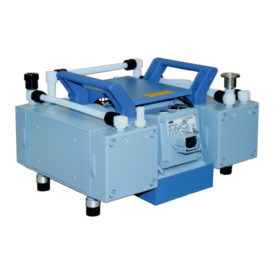
- Page 1 Betriebsanleitung • Operating Instructions Membranvakuumpumpen Diaphragm Vacuum Pumps MVP 035-2, MVP 055-3, MVP 055-3C...
-
Page 2: Table Of Contents
5. What To Do In Case Of Breakdown? ... 11 6. Maintenance.......... 11 6.1. Precautionary Measures During Maintenance Work 11 6.2. Cleaning And Replacing Diaphragms And Valves..12 6.2.1.MVP 035-2 ................. 12 6.2.2.Product-Line MVP 055-3 / MVP 055-3C ......13 7. Service............ 16 8. Technical Data........17 8.1. -
Page 3: Safety Precautions
1. Safety Precautions Read and follow all the instructions in this manual. 1.1. For Your Orientation Inform yourself regarding: Hazards which can be caused by the pump; Instructions in the text Hazards which can arise in your system; ➡... -
Page 4: Understanding The Pump
40 Gas ballast valve The Diaphragm Vacuum Pumps Series MVP 055-3/3C are Diaphragm Vacuum Pump MVP 055-3C with small flange connection three stage and the pumps of the MVP 035-2 series are two A1 Vacuum flange Voltage supply stage dry compressing pumps. This means that any medium 2.1 Exhaust connection... -
Page 5: Differences Between The Pump Types
Gas ballast version: protected electrical supply and a suitable earth point. To avoid condensation in the pump, the MVP 035-2, the – Ensure that installation is in compliance with limitations MVP 055-3C are fitted with a gas ballast valve as standard. -
Page 6: Installation
– The vacuum connection (intake side) is provided with a 1m plastic hose and G 1/4“ screw (option: small flange) for connection to a PFEIFFER turbopump. – The exhaust connection of the MVP 035-2 is provided with a silencer and can also retrovit to small flange connection. -
Page 7: Connecting The Vacuum Side
3.3. Connecting The Vacuum Side 3.5. Connecting To Mains Power The pump is driven by AC motors with the following possible ➡ Remove locking cap on intake connection. variants: ➡ Make connection between the vacuum system and pump as short as possible. Power connections must comply with local ➡... -
Page 8: Adjusting Voltage Selector
3.5.1. Adjusting Voltage Selector The respective single phase mains voltage must be checked before each installation or re-location of the diaphragm pump. Use an appropriate screwdriver on the diaphragm pump voltage selector switch to select the range which corresponds with the mains voltage provided (please see Figure 3.4a). -
Page 9: Operations
4. Operations 4.1. Important Information Important notes regarding the use of gas ballast Make sure that air/gas inlet through the gas Use only “C” version pumps where the pumping DANGER ballast valve never lead to hazardous, explo- of corrosive gases is involved. sive or otherwise dangerous mixtures. -
Page 10: Shutdown
Starting the pump The pump can be switched on and off at all times. When starting the pump or system and when the presence of vapour is to be anticipated it is recommended to open the gas ballast valve in advance. If the intake pressure of the pump increases or PLEASE NOTE is unusually high, the valve can also be opened... -
Page 11: What To Do In Case Of Breakdown
5. What To Do In The Case Of Breakdowns ? Problem Possible cause Remedy • Condensate in the pump • Run pump for a longer period under Pump does not attain final pressure atmospheric pressure; open gas ballast valve. • Open gas ballast valve •... -
Page 12: Cleaning And Replacing Diaphragms And Valves
6.2. Cleaning And Replacing Diaphragm And valve seals 11. Valves ➡ Taking care with the position of valve seals 11, remove and 6.2.1. MVP 035-2 check for damage, and replacing if necessary. ➡ Clean all parts. ➡ Allow the pump to cool down before beginning ➡... -
Page 13: Product-Line Mvp 055-3 / Mvp 055-3C
Changing the Diaphragm 6.2.2. Product-Line MVP 055-3 / MVP 055-3C ➡ Dismantle pump stage as per Section 6.2.1. ➡ Remove screw 16. Caution, this screw has been stuck to Cleaning make secure against loosening. ➡ Detach the pump from the vacuum system and ensure the ➡... - Page 14 The diaphragm is a double diaphragm of total PLEASE NOTE thickness 1.6 mm. The diaphragms are specially selected and are supplied in pairs with a maximum tolerance of 1.6 ± 0.05 mm. Replacement diaphragms must be selected on the same basis. ➡...
- Page 15 ➡ Fit new diaphragm 10 between diaphragm spring washer 3 Changing the Diaphragms on MVP 055-3C ➡ Dismantle pump stages as per Section 6.2.2. and diaphragm support washer 9. ➡ In addition, the front housing cover panel 6 must be ➡...
-
Page 16: Service
7. Service Do Make Use Of Our Service Facilities Decontaminate units before returning or In the event that repairs are necessary to your pumping possible disposal. Do not return any units which are microbiologically, explosively or radio- station, a number of options are available to you to ensure actively contaminated. -
Page 17: Technical Data
8. Technical Data Feature Unit MVP 035-2 MVP 055-3 MVP 055-3C Connections Intake side 1) hose connection with G 1/4“ hose connection with G 1/4“ Small flange DN 16 swivelling screw fitting swivelling screw fitting Pressure side G 1/4“ with silencer G 1/4“... -
Page 18: Dimensions
8.1. Dimensions MVP 035-2 ca. 263... - Page 19 MVP 055-3, MVP 055-3C ca./approx. 235 (241) 314 (321) ca./approx. 262 (266) Measurements in brackets only valid for MVP 055-3C MVP033-3C...
-
Page 20: Substances Which Come Into Contact With The Medium
Small flange connection with seal ring 1 DN 16 ISO-KF PK 050 114-T not included in the for MVP 035-2 (for intake or outlet side) delivery consignment Small flange connection with seal ring 1 DN 16 ISO-KF PK 050 115-T... -
Page 21: Spare Parts
10. Spare Parts Spare part list MVP 035-2 Pos. Description Pieces Set of seals Pos. 10, 11 PK 050 116-T Silencer P0 920 412 E Usit seal ring 13,2 x 18 x 1,5 1 (of 13) P 3529 143-C Hose connection, complete... -
Page 22: Contamination Declaration
Declaration of Contamination of Vacuum Equipment and Components The repair and/or service of vacuum components will only be The manufacturer could refuse to accept any equipment carried out if a correctly completed declaration has been without a declaration. submitted. Non-completion will result in delay. This declaration can only be completed and signed by authorised and qualified staff: 1. - Page 23 Machinery Directive 98/37/EEC - Annex II A, EU Electromagentic Compatibility Directive 89/336/EEC and EU Low Voltage Directive 73/23/EEC. Produkt/Product: MVP 035-2, MVP 055-3, MVP 055-3C. Angewendete Richtlinien, harmonisierte Normen und angewendete, nationale Normen in Sprachen und Spezifikationen: Guidelines, harmonised standards, national standards in languages and specifications which have...
- Page 24 Latvia, Lithuania, Maldavia, Philippines, P.R. China, France Unilaser Lda, Taguspark Rumania, Russia, Tajikistan, Turkmenistan, Ukraine, Uzbeki- Pfeiffer Vacuum France SAS 45, rue Senouque, BP 139 Núcleo Central, sala n 268, stan, Vietnam F-78531 BUC Cedex, Phone: +33 / (0)1 30 83 04 00, Estrada Cacém Porto Salvo, P-2780 Oeiras...
Need help?
Do you have a question about the MVP 035-2 and is the answer not in the manual?
Questions and answers