
Related Manuals for Pfeiffer Vacuum MVP 015-2 DC NEO


Summary of Contents for Pfeiffer Vacuum MVP 015-2 DC NEO
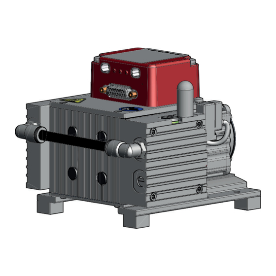
- Page 1 OPERATING INSTRUCTIONS Translation of the Original MVP 015-2 DC NEO Diaphragm pump...
-
Page 2: Telegram Example
Dear Customer, Thank you for choosing a Pfeiffer Vacuum product. Your new diaphragm pump is designed to support you with its performance, perfect operation and without impacting your individual application. The name Pfeiffer Vacuum stands for high-quality vacuum technology, a comprehensive and complete range of top-quality products and first-class service. -
Page 3: Table Of Contents
Limits of use of the product Proper use Foreseeable improper use Personnel qualification 2.7.1 Ensuring personnel qualification 2.7.2 Personnel qualification for maintenance and repair 2.7.3 Advanced training with Pfeiffer Vacuum Product description Function 3.1.1 Actuator 3.1.2 Pumping system 3.1.3 Cooling 3.1.4 Gas ballast... - Page 4 Reference value inputs Operation Commissioning vacuum pump Switching on the vacuum pump Operating the diaphragm pump with gas ballast Configuring connections with Pfeiffer Vacuum parameter set 8.4.1 Configuring the digital outputs 8.4.2 Selecting the interfaces 8.4.3 Configuring accessories Operating modes 8.5.1 Normal operation...
- Page 5 Table of contents Certificate EC Declaration of Conformity UK Declaration of Conformity 5/62...
- Page 6 List of tables List of tables Tbl. 1: Variants Tbl. 2: Stickers on product Tbl. 3: Abbreviations used in this document Tbl. 4: Permissible ambient conditions Tbl. 5: Connection description of the electronic drive unit Tbl. 6: Pin assignment of the D-Sub socket, 15-pin Tbl.
- Page 7 List of figures List of figures Fig. 1: Position of the stickers on the product Fig. 2: Diaphragm pump design Fig. 3: Connecting grounding cable Fig. 4: Connection with turbopump, power supply pack and controller Fig. 5: Connection to control unit with integrated power supply pack Fig.
-
Page 8: About This Manual
Keep the manual for future consultation. 1.1 Validity These operating instructions are a customer document of Pfeiffer Vacuum. The operating instructions describe the functions of the named product and provide the most important information for the safe use of the device. The description is written in accordance with the valid directives. The information in these operating instructions refers to the product's current development status. -
Page 9: Pictographs
This section describes all the stickers on the product along with their meanings. Rating plate (example) D-35614 Asslar Berliner Strasse 43 The rating plate is located on the cover of the electronics. Mod. MVP 015-2 DC Neo PK T05 15x xxxxxxxxx S (N ) 1.0 m /h Mass 2.7 kg... -
Page 10: Abbreviations
About this manual Fig. 1: Position of the stickers on the product 1 Rating plate of the diaphragm pump Operating instructions note 2 Warranty seal (2×) Warning of hot surfaces 1.3.4 Abbreviations Abbreviation Meaning in this document Direct current Nominal diameter (diamètre nominal) Rotation speed value of a vacuum pump (frequency, in rpm or Hz) Light emitting diode Diaphragm vacuum pump... -
Page 11: Safety
Safety 2 Safety 2.1 General safety information The following 4 risk levels and 1 information level are taken into account in this document. DANGER Immediately pending danger Indicates an immediately pending danger that will result in death or serious injury if not observed. ►... - Page 12 ► Install suitable touch protection if the vacuum pump is unrestrictedly accessible. ► Allow the vacuum pump to cool down before carrying out any work. ► Contact Pfeiffer Vacuum for suitable touch protection in system solutions. CAUTION Danger of injury from bursting as a result of high pressure in the exhaust line Faulty or inadequate exhaust pipes lead to dangerous situations, e.g.
- Page 13 Safety WARNING Explosion hazard from reactive, potentially explosive or other hazardous gas/air mixtures Uncontrolled inlet of gas at the gas ballast valve leads to sparks generated mechanically following diaphragm rupture, hot surfaces or to potentially explosive gas/air mixtures in the vacuum system caused by static electricity.
-
Page 14: Safety Precautions
Safety Risks during disposal WARNING Health hazard through poisoning from toxic contaminated components or devices Toxic process media result in contamination of devices or parts of them. During maintenance work, there is a risk to health from contact with these poisonous substances. Illegal disposal of toxic sub- stances causes environmental damage. -
Page 15: Limits Of Use Of The Product
► Use the vacuum pump for vacuum generation only. ► Adhere to the installation, commissioning, operating, and maintenance instructions. ► Use only accessory parts recommended by Pfeiffer Vacuum. 2.6 Foreseeable improper use Improper use of the product invalidates all warranty and liability claims. Any use that is counter to the purpose of the product, whether intentional or unintentional, is regarded as improper use;... -
Page 16: Personnel Qualification
─ Customer with Pfeiffer Vacuum service training ─ Pfeiffer Vacuum service technician 2.7.3 Advanced training with Pfeiffer Vacuum For optimal and trouble-free use of this product, Pfeiffer Vacuum offers a comprehensive range of courses and technical trainings. For more information, please contact Pfeiffer Vacuum technical training. -
Page 17: Product Description
Product description 3 Product description 3.1 Function Diaphragm pumps are dry compressing displacement pumps. The movement of diaphragms generates a periodic change of the suction chamber volume. The gas flow causes the valves to open and close automatically. The pump unit is directly connected to the drive motor. Fig. -
Page 18: Connections
Connection description of the electronic drive unit 3.3 Identifying product ► To ensure clear identification of the product when communicating with Pfeiffer Vacuum, always keep all of the information on the rating plate to hand. ► Learn about certifications through test seals on the product or at www.tuev-sued.de. -
Page 19: Transportation And Storage
Transportation and Storage 4 Transportation and Storage 4.1 Transporting the vacuum pump WARNING Danger of serious injury due to falling objects Due to falling objects there is a risk of injuries to limbs through to broken bones. ► Take particular care and pay special attention when transporting products manually. ►... -
Page 20: Installation
NOTICE Property damage from contaminated gases Pumping gases that contain contamination damages the vacuum pump. ► Use suitable filters or separators from the Pfeiffer Vacuum range of accessories, to protect the vacuum pump. Installation and operation of accessories Pfeiffer Vacuum offers a series of special, compatible accessories for its diaphragm pumps. -
Page 21: Establishing The Electric Connection
► Install a suitable exhaust line. ► Wear hearing protection. Condensate separator Pfeiffer Vacuum recommends installing a condensate separator, with condensate drain at the lowest point of the exhaust line. Procedure 1. Check the installed silencer for free passage. -
Page 22: Grounding Vacuum Pump
Installation 5.4.1 Grounding vacuum pump Fig. 3: Connecting grounding cable Procedure 1. Use a suitable grounding cable to divert applicative interferences. 2. Route the connection in accordance with locally applicable provisions. 3. Use the designated ground terminal on the cover (M4 female thread) on the vacuum pump. 5.4.2 Establishing electric connection DANGER Danger to life from electric shock... -
Page 23: Fig. 4: Connection With Turbopump, Power Supply Pack And Controller
► Insert the connection cable into the connection "DC out" on the power supply pack and close the bayonet lock. ► If you are using a Pfeiffer Vacuum control unit: Connect the “RS-485” connector to the control unit using a suitable extension cable. -
Page 24: Interfaces
The following specifications are the factory settings for the electronic drive unit. Configuring “remote” interface ► Utilize the screened plug and cable. ► Configure the inputs and outputs via the Pfeiffer Vacuum parameter set. Fig. 6: Pins of the D-Sub socket, 15-pin Function... -
Page 25: Voltage Supply
Pin assignment of the D-Sub socket, 15-pin 6.1.1 Voltage supply Input/pin 1 The electrical connection is made using a connection cable from the Pfeiffer Vacuum accessory range or, by the customer, at pin 1 and pin 15. +24 V DC* output/pin 7 A connection with +24 V DC to pin 7 (active high) activates inputs 2 to 6. -
Page 26: Rs-485
Tbl. 8: Output DO2/pin 9 6.1.4 RS-485 Connecting RS-485 via D-Sub ► Connect a Pfeiffer Vacuum control unit or an external PC via pin 13 and pin 14 at the D-Sub con- nection of the electronic drive unit. 6.2 Interface RS-485 DANGER... -
Page 27: Pfeiffer Vacuum Protocol For Rs-485 Interface
Connection cable with RS-485 6.4 Pfeiffer Vacuum protocol for RS-485 interface 6.4.1 Telegram frame The telegram frame of the Pfeiffer Vacuum protocol contains only ASCII code characters [32; 127], the exception being the end character of the telegram C . Basically, a host (e.g. -
Page 28: Telegram Example
Interfaces Error message --> NO_DEF Parameter number n2–n0 no longer exists _RANGE Data dn–d0 outside the permissible range _LOGIC Logical access error 6.4.3 Telegram example 1 Data query Current rotation speed (parameter [P:309], device address: "123") --> ASCII Data response: 633 Hz Current rotation speed (parameter [P:309], device address: "123") -->... - Page 29 Interfaces Data type Description Length Example l1 – l0 u_expo_new Positive exponential number. The 100023 is equivalent to last of both digits are the exponent 1,0 · 10 with a deduction of 20. 100000 is equivalent to 1,0 · 10 string16 Any character string with 16 charac- BrezelBier&Wurst...
-
Page 30: Parameter Set
Each parameter has a three-digit number and a description. The parameter can be accessed via Pfeiffer Vacuum control units or externally via RS-485 using Pfeiffer Vacuum protocol. The electronic drive unit is pre-programmed in the factory. This makes a more direct and safe operation of the vacuum pump possible without additional configuration. -
Page 31: Status Requests
Parameter set Indicator Designations Functions Data Unit min. max. type cess fault type PurgeGas 0 = off Flushing gas 1 = on CtrlViaInt Operate via in- 1 = remote terface 2 = RS-485 4 = PV.can 255 = Interface selection IntSelLckd Interface selec- 0 = off... -
Page 32: Reference Value Inputs
Parameter set Indicator Designations Func- Data Access Unit min. max. tions type type fault ElecName Device name designation HW Version Hardware version interface circuit board Serial number Example: 12345678 Order number Example: PK T05 1xx ActualSpd Actual rotation speed (rpm) NominalSpd Nominal rotation speed (rpm) Tbl. -
Page 33: Operation
Operation 8 Operation 8.1 Commissioning vacuum pump WARNING Danger of poisoning due to toxic process media escaping from the exhaust pipe During operation with no exhaust line, the vacuum pump allows exhaust gases and vapors to escape freely into the air. There is a risk of injury and fatality due to poisoning in processes with toxic process media. -
Page 34: Operating The Diaphragm Pump With Gas Ballast
Behavior with process gases with condensable vapors ► Operate the vacuum pump with gas ballast, i.e. with the gas ballast valve open. 8.4 Configuring connections with Pfeiffer Vacuum parameter set The electronic drive unit is pre-configured with the factory default basic functions and is ready for opera- tion. -
Page 35: Selecting The Interfaces
Operation Option Description 10 = always 1 V+ for the control of an external device 11 = Remote active, if the remote priority is active Tbl. 15: Configure parameters [P:019] and [P:024] Procedure ► Perform the configuration according to the table. 8.4.2 Selecting the interfaces Option [P:060] Description... -
Page 36: Operating Modes
● Operation via an external control unit ● Operation via RS-485 and Pfeiffer Vacuum control unit or PC The connection of a Pfeiffer Vacuum control unit permits the controlling of the vacuum pump via the pa- rameters fixed in the electronic drive unit. -
Page 37: Speed Actuator Operation
Operation 8.5.3 Speed actuator operation Permissible rotation speed range of the vacuum pump Parameterization in rotation speed setting mode is subject to the permissible rotation speed range of the respective vacuum pump. The electronic drive unit regulates automatically to the next valid value. The set rotation speed is selected via the parameter [P:707] in the range 30 to 170 % of the set rotation speed. -
Page 38: Tbl. 17: Correction Factor For Pressure Range < 1 Hpa
Operation Gas type Correction factor (C) Water vapor Helium (He) Neon (Ne) Argon (Ar) Krypton (Kr) Xenon (Xe) Dichlorodifluoromethane (CCl , R12) The correction factors provided are mean values. Tbl. 17: Correction factor for pressure range < 1 hPa p [hPa] Freon 12 –1 Water vapor... -
Page 39: Operation Monitoring
8.7.1 Operating mode display via LED LEDs on the electronic drive unit show the basic operating states of the vacuum pump. A differentiated error and warning display is only possible for operation with the Pfeiffer Vacuum control unit or a PC. Symbol... -
Page 40: Switching Off The Vacuum Pump
Operation 8.8 Switching off the vacuum pump Procedure 1. Allow the vacuum pump to run on for 5 to 10 minutes with the vacuum connection open to allow any condensate that may be present to be removed from the vacuum pump. 2. -
Page 41: Maintenance
► Do not use any alcohol or other cleaning agents to clean the diaphragms and valves. NOTICE Danger of property damage from improper maintenance Unprofessional work on the vacuum pump will lead to damage for which Pfeiffer Vacuum accepts no liability. ► We recommend taking advantage of our service training offering. -
Page 42: Checklist For Inspection And Maintenance
We recommend that Pfeiffer Vacuum Service carry out maintenance work. If the specified intervals are exceeded, or if maintenance work is carried out improperly, no warranty or lia- bility claims are accepted on the part of Pfeiffer Vacuum. This also applies wherever parts other than original spare parts are used. -
Page 43: Change The Diaphragms And Valves
Maintenance Action Inspection Maintenance Required material Interval as required; as required; at least once ev- at least every 2 years ery six months ■ Filter Change gas ballast filter Replace wear parts ■ Diaphragms, valves, seal- ing rings, silencers Tbl. 20: Maintenance intervals 9.3 Change the diaphragms and valves NOTICE... -
Page 44: Dismantling Diaphragm Head And Valves
Maintenance 9.3.2 Dismantling diaphragm head and valves Prerequisite ● Interconnection hose removed Required tools ● Allen key, WAF 4 Fig. 12: Diaphragm head and valves 1 Silencer Intermediate plate 2 Cylinder screws Diaphragm 3 Diaphragm head cover Spacer disks 4 Valve plate Interconnection hose 5 Sealing ring (only on diaphragm head A) Procedure... -
Page 45: Mounting Diaphragm Head And Valves
Maintenance 3. Check valve seats, intermediate plate and head cover for wear. 4. Replace all wear parts according to the inspection sets. 9.3.4 Mounting diaphragm head and valves Spacer disks Spacer disks are available in 3 sizes: ● 13.0 × 6.4 × 0.5 mm ●... -
Page 46: Decommissioning
Decommissioning 10 Decommissioning Before shutting down the vacuum pump, observe the following instructions to adequately protect the in- terior of the vacuum pump (suction chamber) from corrosion: Procedure for temporary vacuum pump shutdowns 1. Allow the vacuum pump to run on for 5 to 10 minutes with the vacuum connection open to allow any condensate that may be present to be removed from the vacuum pump. -
Page 47: Recycling And Disposal
– Fluoroelastomers (FKM) – Potentially contaminated components that come into contact with media 11.2 Dispose of diaphragm pumps Pfeiffer Vacuum diaphragm pumps contain materials that you must recycle. 1. Disconnect the electronic drive unit. 2. Dismantle the motor. 3. Decontaminate the components that come into contact with process gases. -
Page 48: Malfunctions
► Wear personal protective equipment if necessary. NOTICE Danger of property damage from improper maintenance Unprofessional work on the vacuum pump will lead to damage for which Pfeiffer Vacuum accepts no liability. ► We recommend taking advantage of our service training offering. -
Page 49: Error Codes
Warnings (* Warning F –––– *) do not cause the vacuum pump to be switched off. Handling malfunction messages 1. Read out error codes via Pfeiffer Vacuum control units or a PC. 2. Remove the cause of the malfunction. 3. Reset the malfunction message with parameter [P:009]. - Page 50 Malfunctions Error code Problem Possible causes Remedy Err173 Vacuum pump overcurrent ● Contact Pfeiffer Vacuum Service Err174 Vacuum pump blocked – ● Contact Pfeiffer Vacuum Service Tbl. 22: Error messages for vacuum pump Error code Problem Possible causes Remedy Wrn042 Maintenance ●...
-
Page 51: Service Solutions By Pfeiffer Vacuum
We are always focused on perfecting our core competence – servicing of vacuum components. Once you have purchased a product from Pfeiffer Vacuum, our service is far from over. This is often exactly where service begins. Obviously, in proven Pfeiffer Vacuum quality. - Page 52 Service solutions by Pfeiffer Vacuum 5. Prepare the product for transport in accordance with the provisions in the contamination declaration. a) Neutralize the product with nitrogen or dry air. b) Seal all openings with blind flanges, so that they are airtight.
-
Page 53: Spare Part Packages
Spare part packages 14 Spare part packages Ordering spare part packages ► Have the vacuum pump part number to hand, along with other details from the rating plate if nec- essary. ► Install original spare parts only. ► When ordering the inspection set, observe the respective part number of the diaphragm pump. Fig. -
Page 54: Accessories
Accessories 15 Accessories 15.1 Accessory information Control unit Universal control unit for all products with Pfeiffer Vacuum RS-485 protocol. Power supply packs Power supply packs for fastening to the wall and standard rails or for rack assembly serve the voltage supply. Cable and adapter Mains, interface, connection, and extension cables provide a secure and suitable connection. -
Page 55: Technical Data And Dimensions
Technical data and dimensions 16 Technical data and dimensions 16.1 General Basis for the technical data of Pfeiffer Vacuum diaphragm pumps: ● Specifications according to PNEUROP committee PN5 ● ISO 21360:2012: “Vacuum technology - Standard methods for measuring vacuum-pump perform- ance - General description”... -
Page 56: Substances In Contact With The Media
Technical data and dimensions Type designation MVP 015-2 DC MVP 015-2 DC Current, max. 4.6 A 4.6 A Short circuit current of voltage source, max. 45 A 45 A Nominal rotation speed 1800 rpm 1800 rpm Rotation speed 750 – 2 600 rpm 750 –... -
Page 57: Dimensions
Technical data and dimensions 16.4 Dimensions Inlet G 1/8" 170.5 36.5 26.5 Ø Outlet G 1/8" Fig. 14: Dimensions MVP 015-2 DC Dimensions in mm 57/62... - Page 58 The product MVP 015-2 DC - conforms to the UL standards UL 61010-1:2012/R:2015-07 Safety requirements for electrical equipment for measurement, control and laboratory use Part 1: General requirements - is certified to the CAN/CSA standards CAN/CSA-C22.2 No. 61010-1:2012/U1:2015-07 Safety requirements for electrical equipment for measurement, control and laboratory use Part 1: General requirements...
- Page 59 A2:2021 + A2:2021/AC:2022 EN IEC 55014-1:2021 EN IEC 63000:2018 The authorized representative for the compilation of technical documents is Dr. Adrian Wirth, Pfeiffer Vacuum GmbH, Berliner Straße 43, 35614 Asslar, Germany. Signature: Pfeiffer Vacuum GmbH Berliner Straße 43 35614 Asslar Germany (Daniel Sälzer)
- Page 60 EN IEC 55014-1:2021 EN IEC 63000:2018 The manufacturer's authorized representative in the United Kingdom and the authorized agent for compiling the technical documentation is Pfeiffer Vacuum Ltd, 16 Plover Close, In- terchange Park, MK169PS Newport Pagnell. Signature: Pfeiffer Vacuum GmbH Berliner Straße 43...
- Page 61 61/62...
Need help?
Do you have a question about the MVP 015-2 DC NEO and is the answer not in the manual?
Questions and answers