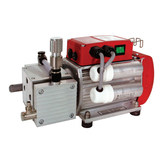
Pfeiffer Vacuum MVP 015-2 Operating Instructions Manual
Diaphragm pump
Hide thumbs
Also See for MVP 015-2:
- Operating instructions manual (40 pages) ,
- Translation of the original (42 pages) ,
- Operating instructions manual (84 pages)

Subscribe to Our Youtube Channel
Related Manuals for Pfeiffer Vacuum MVP 015-2


Summary of Contents for Pfeiffer Vacuum MVP 015-2
- Page 1 Betriebsanleitung • Operating Instructions Translation of the Original Operating Instructions Diaphragm Pump MVP 015-2...
-
Page 2: Table Of Contents
Table of contents Table of contents About this manual ........3 Validity. -
Page 3: About This Manual
1 About this manual 1.1 Validity This operating manual is for customers of Pfeiffer Vacuum. It describes the func- tioning of the designated product and provides the most important information for safe use of the unit. The description follows applicable EU guidelines. All informa- tion provided in this operating manual refer to the current state of the product's de- velopment. -
Page 4: Safety
NOTE Installation and operation of accessories Pfeiffer Vacuum pumps can be equipped with a series of adapted accessories. The in- stallation, operation and maintenance of connected devices are described in detail in the operating instructions of the individual components. -
Page 5: Proper Use
• Installation, operating and maintenance regulations must be complied with. • Other accessories than those described in this manual must not be used without the agreement of Pfeiffer Vacuum. • When pumping gases which could form explosive or ignitable mixtures, take suitable precautions: –... -
Page 6: Transport And Storage
Transport and storage Improper use of the equipment automatically invalidates all warranty and liability claims. 3 Transport and storage 3.1 Transport Lift pump by hand at both face sides. – Do not use the hose connection on the top side of the pump to carry the pump. -
Page 7: Product Description
• Operating instructions 4.2 Function The diaphragm vacuum pump of the series MVP 015-2 is a two stage, dry compres- sor vacuum pump. The pumps are positive displacement pumps with a periodic change of size of the suction chamber produced by the movement of the dia- phragm. -
Page 8: Installation
– Voltage and frequency information given on the motor rating plate must be visible. – Keep the ventilation openings at the motor free, in order to provide sufficient cooling air. Installation The pump MVP 015-2 must be installed and operated under the following ambient conditions: conditions Installation location weather protected (indoors) -
Page 9: Connecting To The Mains Power Supply
Installation Lay piping from the pump sloping downward so that no condensate can flow back into the pump; otherwise fit a condensate separator. – If an air trap is created in the system, then a device for draining condensation water must be provided at the lowest point. - Page 10 Installation The mains voltage must be determined on-site each time before the pump is in- Single phase motors stalled or moved to a different location. NOTE Overvoltage! An incorrect voltage range setting can damage the motor. Disconnect the pump from the power supply. ...
-
Page 11: Operation
Operation 6 Operation 6.1 Before switching on the pump Compare the voltage information on the rating plate with the mains voltage. Check that the exhaust connection allows free flow (max. permissible pressure 1.1 bar absolute). – Activate the shut-off valves in such a way that they open before or at the same time as the pump is started. -
Page 12: Pumping Condensable Vapours
Operation 6.3 Pumping condensable vapours Should the process gases contain condensable gases present at high percentages, the vacuum pump must be operated with a gas ballast (i.e. with an open gas ballast valve). WARNING Reactive, explosive or otherwise dangerous mixtures! Uncontrolled gas inlet at the gas ballast valve can result in dangerous mixtures. -
Page 13: Maintenance
NOTE Service work should be carried out by qualified personal only! Pfeiffer Vacuum is not liable for any damage to the pump resulting from work carried out improperly. Take advantage of our service training programs; additional information at www.pfe- iffer-vacuum.net. -
Page 14: Cleaning And Replacing Diaphragm And Valves
Checklist for inspec- Certain repair and overhaul work should only be performed by Pfeiffer Vacuum Service (PV). Pfeiffer Vacuum will be released from all warranty and liability claims tion, maintenance if the required intervals for inspection, maintenance, or overhaul are exceeded or... -
Page 15: Cleaning The Gas Ballast Valve
Maintenance Remove intermediate plate 5; be careful with valve plate 3. Lift the diaphragm 6 slightly on the edge and manually unscrew from the con- necting rod (right-hand thread); be careful with spacer disk D. Assembling is carried out in reverse order. Assembling ... -
Page 16: Replacing The Device Fuses
Maintenance 7.4 Replacing the device fuses The microfuses (5 x 20 / 3,15A T) are located in a fuse carrier in the terminal box. WARNING Voltage-bearing elements Danger to life from electric shock. The fuses can be changed only by trained and authorised electricians. ... -
Page 17: Decommissioning
Decommissioning 8 Decommissioning 8.1 Shutting down for longer periods Before shutting down the pump, observe the following procedure and adequately protect the pump system against corrosion: Let the vacuum pump continue to run for several minutes with the intake port Shortly after conden- open. -
Page 18: Rectifying Malfunctions
NOTE Service work should be carried out by qualified personal only! Pfeiffer Vacuum is not liable for any damage to the pump resulting from work carried out improperly. Take advantage of our service training programs; additional information at www.pfe- iffer-vacuum.net. -
Page 19: Service
Fill in the "Service Request" form and send it by fax or e-mail to your service ad- dress. Include the confirmation on the service request from Pfeiffer Vacuum with your shipment. Fill in the contamination declaration and enclose it in the shipment (required!). -
Page 20: Spare Parts
Spare parts 11 Spare parts Spare part package/ Spare parts No. Pieces consisting of the parts Set of wearing parts PU E22 001 -T 3, 4, 6, 14, 15, 39 Silencer P 0920 567 E Hose connection PK 050 002 -T Intake hose P 0991 939 1m/6x1... -
Page 21: Accessories
Screw-in flange DN 16 ISO-KF / G 1/8" incl. seal PK 050 108-T Hose connection DN 6x400 mm with straight fit- P 0920 739 E ting G 1/8" and G 1/4" including sealing rings Further detailed accessories are contained in the Pfeiffer Vacuum printed or Online Catalogue. -
Page 22: Technical Data And Dimensions
The following harmonised standards are fulfilled: • IEC 61010-1 • UL 61010-1 • CSA 61010-1 13.2 Technical data MVP 015-2 Parameter MVP 015-2 Flange (in) G 1/8" elbow union + enclosed hose DN 6 x 1000 mm with a straight union in G 1/4" at the Flange (out) G 1/8"... -
Page 23: Dimensions
Technical data and dimensions 13.4 Dimensions ø20 Abb. 6: MVP 015-2... -
Page 24: Declaration Of Conformity
In addition, the product cited below satisfies all relevant provisions of EC directive "Electromagnetic Compatibility" 2004/108/EC . The agent responsible for compiling the technical documentation is Mr. Sebastian Oberbeck, Pfeiffer Vacuum GmbH, Berliner Straße 43, 35614 Aßlar. MVP 015-2 Guidelines, harmonised standards and national standards and specifications... - Page 25 Roots pumps Dry compressing pumps Leak detectors Valves Components and feedthroughs Vacuum measurement Gas analysis System engineering Service Pfeiffer Vacuum Technology AG · Headquarters/Germany Tel. +49-(0) 64 41-8 02-0 · Fax +49-(0) 64 41-8 02-2 02 · info@pfeiffer-vacuum.de · www.pfeiffer-vacuum.net...
Need help?
Do you have a question about the MVP 015-2 and is the answer not in the manual?
Questions and answers