Table of Contents
Advertisement
Quick Links
QSE (Q-Star) Series Electromagnetic Meter
Owner's Manual
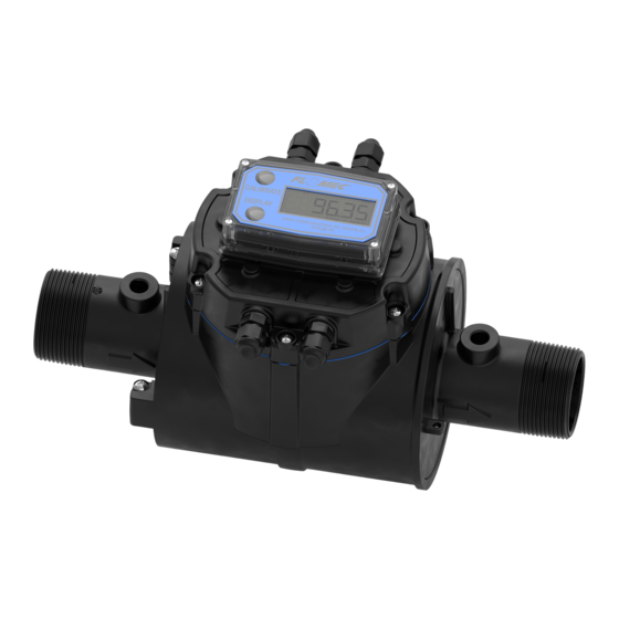
NPT Meter
(1/2 in. to 2 in.)
Shown with Display Mount
Cover Plate and Display
NPT OR BSP METER
WITH 09 ELECTRONICS
TABLE OF CONTENTS
INTRODUCTION ..................................... 1
IMPORTANT NOTICE ....................... 2
PRINCIPLE OF OPERATION ............ 2
SAFETY ............................................ 2
INSTALLATION ....................................... 3
EARTH GROUND ............................. 3
Grounding Summary: ....................... 3
CONNECTIONS ............................... 6
RECOMMENDED INSTALLATION .... 8
WIRING ............................................ 9
MAINTENANCE ...................................... 9
TROUBLESHOOTING .......................... 10
SPECIFICATIONS ................................. 11
U.S. MEASUREMENT .................... 12
METRIC MEASUREMENT .............. 13
U.S. PRODUCT WEIGHT ............... 14
METRIC PRODUCT WEIGHT ......... 14
DIMENSIONS ................................. 15
TEMPERATURES ........................... 16
REPLACEMENT PARTS LIST ............... 19
SERVICE ............................................... 21
LIMITED WARRANTY ........................... 24
10/2018
BSPP Meter
(1/2 in. to 2 in.)
Shown with Display Mount
Cover Plate and Display
BSPP METER WITH
09 ELECTRONICS
ANSI Flanged Meter
(3 in. & 4 in.)
3" POLYMER FLANGE METER WITH QB ELECTRONICS
Shown with Plain Cover Plate
and Pulse Out Transmitter (QSB)
INTRODUCTION
The QSE meter has multiple types
of output electronics available.
The electronics for the operation
of the meter coils and flow tube
are housed within the meter body
casing. The cover plate is designed
in two versions; a plain cover plate
or a display mount cover plate. The
output electronics (QSB, QSI1, QSI2
or QSI3) can be housed within either
of the two cover plates. A display
(Q09) is also available mounted to
the "display mount" cover plate. All
meters are equipped with galvanically
isolated pulse-out electronics
(QSB) as the default standard,
regardless of style of cover plate.
This manual contains overall
information related only to the meter.
This meter is externally powered
and all external wiring connects
to the electronics within the cover
plate through its threaded ports.
920896-01 Rev T
Advertisement
Table of Contents

Related Manuals for Flomec QSE Series


Summary of Contents for Flomec QSE Series
-
Page 1: Table Of Contents
QSE (Q-Star) Series Electromagnetic Meter Owner’s Manual NPT Meter BSPP Meter ANSI Flanged Meter (1/2 in. to 2 in.) (1/2 in. to 2 in.) (3 in. & 4 in.) 3" POLYMER FLANGE METER WITH QB ELECTRONICS Shown with Display Mount Shown with Display Mount Shown with Plain Cover Plate Cover Plate and Display... -
Page 2: Important Notice
Faraday’s Law of Electromagnetic the main meter body receive power Induction is the operating principle from the electronics housed within on which the QSE series meters are the cover plate through a ribbon based. Faraday’s Law (paraphrased) cable. See the included electronics... -
Page 3: Installation
INSTALLATION EARTH GROUND By connecting the QSE sensor, When making installations, the the fluid, and the reference used magnetic flow meter grounding rules have to be observed. The sensors by the internal electronics to a of the QSE flow meter are sensitive stable, noise free reference point to any electrical noise that is always (earth ground), the user is ensured... - Page 4 QSE GROUNDING - THREADED FITTINGS & ANSI FLANGE ALL PROCESS PIPE MATERIALS USING GPI GROUNDING PROBES (Kit P/N 145630-529) CONNECT WIRE TO RING TERMINAL. TIGHTEN RING TERMINAL WITH SCREW. QSE GROUNDING - THREADED FITTINGS & ANSI FLANGE (3 PLACES) ALL PROCESS PIPE MATERIALS USING GPI GROUNDING PROBES (Kit P/N 145630-529) CONNECT WIRE TO RING TERMINAL.
- Page 5 QSE GROUNDING - ANSI FLANGE QSE GROUNDING - ANSI FLANGE NON-CONDUCTIVE (PLASTIC) PIPE NON-CONDUCTIVE (PLASTIC) PIPE USING COMMERCIALLY AVAILABLE GROUNDING RINGS USING COMMERCIALLY AVAILABLE GROUNDING RINGS CONNECT WIRE TO RING TERMINAL. CONNECT WIRE TO RING TERMINAL. TIGHTEN RING TERMINAL WITH SCREW. TIGHTEN RING TERMINAL WITH SCREW.
-
Page 6: Connections
TYPICAL INSTALLATION Plan to install meter with minimum straight pipe lengths at inlet and CONNECTIONS outlet ends. The straight run lengths noted below represent Install your meter in-line with either the minimum requirements for horizontal flow or vertical flow. The accurate flow measurement best meter position for horizontal (see Figure 5). - Page 7 For NPT Fittings: Seal all pipe threads with an appropriate non-lubricated thread ® sealant (such as Loctite More Leaks™ Plastic Pipe Thread Sealant or NSF equivalent for NSF applications). Make sure the thread 1. Install O-ring 2. Install backup sealant does not intrude into the ring flow path.
-
Page 8: Recommended Installation
RECOMMENDED INSTALLATION and snap into place. Each end of a half-ring has a small lobe WARNING: Compatibility of that snaps into a recess at the this product’s material and the top and bottom of the groove for process fluid and/or environment retention. -
Page 9: Wiring
WIRING • Cable to be provided by customer to accommodate All electronic options are associated job requirements. Cable is with a matching style of meter not included with meter. cover plate. This cover plate has • This meter is externally four threaded ports, compatible powered. -
Page 10: Troubleshooting
TROUBLESHOOTING MEASUREMENT IS NOT ACCURATE PROBABLE CAUSE SOLUTION Debris/particles in liquid Need proper filtration Increase back pressure on Air in liquid - No back pressure meter to eliminate air Install meter away from other fittings Air in liquid - Plumbing installation or flow obstructions. -
Page 11: Specifications
SPECIFICATIONS WETTED COMPONENTS Design Type: Electromagnetic INLET AND OUTLET NORYL™ Housing GFN3 PPE+PS NPT MODELS 316L Stainless QSE05NPT 1/2 inch NPT Electrodes Steel QSE07NPT 3/4 inch NPT Temperature 316 Series QSE10NPT 1 inch NPT Probes Stainless Steel QSE15NPT 1-1/2 inch NPT 300 Series Pipe Plugs QSE20NPT... -
Page 12: U.s. Measurement
U.S. MEASUREMENT Unit of Measure: Gallon TURNDOWN 60:1 ACCURACY Typ. Flow Range Line Size ACCURACY ±Uncertainty K-factor (GPM) (PPG) 0.16 to 10 gpm ± 0.5% of ± 0.023 ± .015 1/2 inch 4347 (.25 to 15 fps) Reading 0.33 to 20 gpm ±... -
Page 13: Metric Measurement
METRIC MEASUREMENT Unit of Measure: Litre TURNDOWN 60:1 ACCURACY Typ. Line Flow Range ACCURACY ±Uncertainty K-factor Size (L/min) (PPL) 0.63 to 38 L/min ± 0.5% of ± 7.0 ± .057 1148.5 inch [.076 to 4.57 m/s] Reading mm/s L/min 1.27 to 76 L/min ±... -
Page 14: U.s. Product Weight
U.S. PRODUCT WEIGHT PRODUCT WEIGHT – lb:* ANSI Polymer ANSI Steel DIN Steel NPT / BSPP Flange Flange Flange 1/2 in. 3/4 in. 1 in. 1 1/2 in. 2 in. 3 in. 24.4 22.5 4 in. 16.3 29.5 23.7 * Weight with display. For plain cover plates, subtract 0.2 lb. METRIC PRODUCT WEIGHT PRODUCT WEIGHT –... -
Page 15: Dimensions
DIMENSIONS 6.31 [160.2] ALL METERS NPT / BSPP WITH 09 ELECTRONICS NPT / BSPP WITH QB ELECTRONICS FLANGE WITH 09 ELECTRONICS FLANGE WITH QB ELECTRONICS QSE METER DIMENSIONS (NPT, BSP, FLANGE) QSE METER DIMENSIONS (NPT, BSPP, ANSI FLANGE, DIN FLANGE) METER SIZE &... -
Page 16: Temperatures
TEMPERATURES ... -
Page 17: Fluid Electrical Conductivity
Vodka 100 Proof Water, Distilled 0.04 Water, NYC NOTE: This table of fluid conductivity NOTE: QSE series meters are is for reference only, to show the for use with water, aqueous relative conductivity of various fluids. solutions and other non-flammable, Since the list contains flammable electrically conductive fluids. - Page 18 L, N1, N2 & N3 C, D, E, F, P1, P2 G, H & J & P3 K, M1, M2 & M3 S1, S2, S3, S4, S5 & S6 (Polymer flanges shown) A1 & A2 BSPP METER FITTING END V1, V2, V3, V4 & V5...
-
Page 19: Replacement Parts List
REPLACEMENT PARTS LIST REF. PART NUMBER DESCRIPTION REQ’D. Kit, 1 in. temperature sensor probe 145500-01 Includes: (2) probes, (2) strain reliefs w/O-rings Kit, 2 in. temperature sensor probe 145500-02 Includes: (2) probes, (2) strain reliefs w/O-rings. 145500-03 Kit, pipe plug, 1/8-27 NPT stainless steel Includes: (2) plugs. Kit, Q09 computer display, 1/2 in. - Page 20 Kit, O-rings, 1/2 in., 3/4 in. and 1 in. housings. 145500-04 Includes: (2) O-rings. 145500-05 Kit, O-rings, 1-1/2 in. and 2 in. housings. Includes: (2) O-rings. 145500-06 Kit, O-rings, 3 in. and 4 in. housings. Includes: (2) O-rings. 145500-07 Kit, seal, cover plate. Includes: (1) Cover plate seal. Kit, ANSI flange, polymer, 3 in.
-
Page 21: Service
SERVICE The Waste Electrical and Electronic Equipment (WEEE) directive For warranty consideration, contact (2002/96/EC) was approved by the European Parliament and the Council your local distributor. If you need of the European Union in 2003. This further assistance, contact the GPI symbol indicates that this product Customer Service Department at: contains electrical and electronic... - Page 22 NOTES...
- Page 23 NOTES...
-
Page 24: Limited Warranty
Note: In compliance with MAGNUSON MOSS CONSUMER WARRANTY ACT – Part 702 (governs the resale availability of the warranty terms). IP67 © 2018 Great Plains Industries, Inc., All Rights Reserved. Great Plains Industries, Inc. / 888-996-3837 / FLOMEC.net 10/2018 920896-01 Rev T...
Need help?
Do you have a question about the QSE Series and is the answer not in the manual?
Questions and answers