Table of Contents
Advertisement
Quick Links
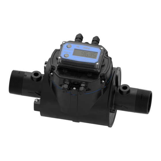
NPT Meter
(1/2 in. to 2 in.)
Shown with Display Mount Cover Plate
and Display
BSPP Meter
(1/2 in. to 2 in.)
Shown with Display Mount
Cover Plate and Display
ANSI Flanged Meter
(3 in. & 4 in.)
Shown with Plain Cover Plate
and Pulse Out Transmitter (QB)
QSE SERIES
ELECTROMAGNETIC METER
12/2022
920896-01 Rev. AF
Advertisement
Table of Contents

Subscribe to Our Youtube Channel
Related Manuals for Flomec QSE Series


Summary of Contents for Flomec QSE Series
- Page 1 BSPP Meter (1/2 in. to 2 in.) Shown with Display Mount Cover Plate and Display ANSI Flanged Meter (3 in. & 4 in.) Shown with Plain Cover Plate and Pulse Out Transmitter (QB) QSE SERIES ELECTROMAGNETIC METER 12/2022 920896-01 Rev. AF...
- Page 2 Please save these instructions for future reference. Read carefully before attempting to assemble, install, operate or maintain the product described. Protect yourself and others by observing all safety information. Failure to comply with instructions could result in personal injury and/or property damage. Please refer to back cover for information regarding this product’s warranty and other important information.
-
Page 3: Table Of Contents
TABLE OF CONTENTS Getting Started --------------------------------------------------------------- 4 General Safety Instructions ---------------------------------------------- 5 Specifications ---------------------------------------------------------------- 6 U.S. Measurement --------------------------------------------- 7 Metric Measurement -------------------------------------------8 U.S. Product Weight ------------------------------------------ 9 Metric Product Weight --------------------------------------- 9 Dimensions ----------------------------------------------------- 10 Temperatures -------------------------------------------------- 11 Fluid Electrical Conductivity ------------------------------------------- 12 Meter Overview ------------------------------------------------------------- 13 Important Notice ---------------------------------------------- 13 Principle of Operation ……………………………….. -
Page 4: Getting Started
BEFORE YOU BEGIN Usage This meter is CSA, CE, UKCA and China RoHS approved and has an IP67 environmental rating. Power Source Requirements This meter requires DC power. For this application, the power is provided by the customer power supply. See meter Specifications section for detailed information. -
Page 5: General Safety Instructions
GENERAL SAFETY INSTRUCTIONS IMPORTANT: It is your responsibility to: Ensure that all equipment operators have access to adequate instructions concerning safe operating and maintenance procedures. This product is not approved for use with petroleum products (diesel fuel, unleaded gasoline, jet fuel, kerosene, etc.), aromatic hydrocarbons or other incompatible chemicals This product is not approved for use in hazardous... -
Page 6: Specifications
SPECIFICATIONS Design Type: Electromagnetic INLET AND OUTLET WETTED COMPONENTS NPT MODELS NORYL™ GFN3 Housing PPE+PS QSE05NPT 1/2 inch NPT 316L Stainless QSE07NPT 3/4 inch NPT Electrodes Steel QSE10NPT 1 inch NPT 300 Series Pipe Plugs QSE15NPT 1-1/2 inch NPT Stainless Steel QSE20NPT 2 inch NPT EPDM... -
Page 7: U.s. Measurement
SPECIFICATIONS (Continued) U.S. Measurement Unit of Measure: Gallon TURNDOWN 60:1 ACCURACY Typ. Flow Range K-factor Line Size ACCURACY ±Uncertainty (GPM) (PPG) 0.16 to 10 gpm ± 0.5% of ± 0.023 ± .015 1/2 inch 4347 Reading (.25 to 15 fps) 0.33 to 20 gpm ±... -
Page 8: Metric Measurement
SPECIFICATIONS (Continued) Metric Measurement Unit of Measure: Litre TURNDOWN 60:1 ACCURACY Typ. K-factor Line Size Flow Range (L/min) ACCURACY ±Uncertainty (PPL) 0.63 to 38 L/min ± 0.5% of ± 7.0 ± .057 1/2 inch 1148.5 Reading mm/s L/min [.076 to 4.57 m/s] 1.27 to 76 L/min ±... -
Page 9: U.s. Product Weight
SPECIFICATIONS (Continued) U.S. Product Weight PRODUCT WEIGHT – lb:* ANSI NPT / BSPP Polymer Flange 1/2 in. 3/4 in. 1 in. 1 1/2 in. 2 in. 3 in. 4 in. 16.3 * Weight with display. For plain cover plates, subtract 0.2 lb. Metric Product Weight PRODUCT WEIGHT –... -
Page 10: Dimensions
SPECIFICATIONS (Continued) Dimensions QSE METER DIMENSIONS (NPT, BSPP, ANSI FLANGE) Listed in inches and Centimeters. Centimeters shown in [ ] brackets METER SIZE & FITTING 1/2 in. 5.20 5.85 10.50 5.13 1.83 NPT & BSPP [13.21] [14.86] [26.67] [13.09] [4.65] 3/4 in. -
Page 11: Temperatures
SPECIFICATIONS (Continued) Temperatures NOTE: It is permissible to use temperature ratings (see Specification section of this manual) for the following electronics if mounted on QSE Series Electromagnetic Meter: QSI Electronics QB Electronics Q9 Display 4-20 mA Module... -
Page 12: Fluid Electrical Conductivity
Since the list contains flammable fluids, it is not to be construed as a list of permissible fluids to be used with QSE series meters. NOTE: QSE series meters are for use with water, aqueous solutions and other non- flammable, electrically conductive fluids. -
Page 13: Meter Overview
(15.2cm) of some electric motors, relays, transformers or other sources of electronic noise. If the QSE series meters are used in a manner not specified by the manufacturer, the protection provided by the equipment may be impaired. Principle of Operation Faraday’s Law of Electromagnetic Induction is the operating principle on which the... -
Page 14: Safety
METER OVERVIEW (Continued) Safety This product is not approved for use with petroleum products (diesel fuel, unleaded gasoline, jet fuel, kerosene, etc.), aromatic hydrocarbons, flammable fluids or other incompatible chemicals This product is not approved for use in hazardous locations. ... - Page 15 INSTALLATION (Continued) GROUNDING - Threaded Fittings - All Process Pipe Materials Using GPI Grounding Probes (Kit P/N 145630-529) Figure 1 GROUNDING - Threaded Fittings - Non-Conductive (Plastic) Pipe Using Commercially Available Metal Couplings Figure 2...
- Page 16 INSTALLATION (Continued) GROUNDING - ANSI Flange - Non-Conductive (Plastic) Pipe Using Commercially Available Grounding Rings Figure 3 METAL PIPE – ANSI FLANGE – Flexible Expansion Joint CAUTION: When installing to metal pipe, it is recommended to use flexible expansion joints on one or both ends to eliminate any stresses that might be incurred from misaligned rigid metal piping.
-
Page 17: Connections
INSTALLATION (Continued) Connections Install your meter in-line with either horizontal flow or vertical flow. The best meter position for horizontal flow setups is with the meter rotated slightly (about 1 o’clock or 2 o’clock) to tilt the top from the horizontal plane (see Figure 4). This prevents sediment from settling on the lower set of sensing electrodes. - Page 18 INSTALLATION (Continued) NPT Fittings Seal all pipe threads with an appropriate non-lubricated thread sealant (such as Loctite® No More Leaks™ Plastic Pipe Thread Sealant). Make sure the thread sealant does not intrude into the flow path. Hand tighten the meter at the housing ends. Do not use a wrench or similar tool to tighten as this can damage the housing.
- Page 19 NOTE: Each end of the flow tube has a boss on top with a recessed floor. The ports can also be used to install a FLOMEC Grounding Probe Kit. To install a FLOMEC Grounding Probe Kit in these meters, the customer must drill and tap the ports per the Grounding Probe Kit instructions.
-
Page 20: Wiring
INSTALLATION (Continued) Wiring All electronic options are associated with a matching style of meter cover plate. This cover plate has four threaded ports, compatible with PG7 threads, for gaining wiring access to the electronics inside the cover plate. The meter is shipped with the ports environmentally sealed with a threaded plug and seal. -
Page 21: Troubleshooting
TROUBLE SHOOTING MEASUREMENT IS NOT ACCURATE PROBABLE CAUSE SOLUTION Debris/particles in liquid Need proper filtration Increase back pressure on meter to Air in liquid - No back pressure eliminate air Install meter away from other fittings or Air in liquid - Plumbing installation flow obstructions. -
Page 22: Maintenance & Service
MAINTENANCE The meter is virtually maintenance- free. However, it is important to keep the meter clean and free of contaminants. CAUTION: Do not allow liquids to dry inside the meter. The electrodes may develop a film that degrades accuracy. Remove internal debris or deposits using soft brush or small probe. NOTE: Make sure the arrow on the meter is pointed in the direction of fluid flow (see Figure 2). -
Page 23: Illustrated Replacement Parts List
ILLUSTRATED REPLACEMENT PARTS LIST PART REF. DESCRIPTION NUMBER REQ’D. Kit, pipe plug, 1/8-27 NPT stainless steel 145500-03 Includes: (2) plugs. Kit, Q9 computer display, 1/2 in. 145501-01 Includes: Computer display w/decal, seal, 10-pin connector. Kit, Q9 computer display, 3/4 in. 145501-02 Includes: Computer display w/decal, seal, 10-pin connector. - Page 24 Kit, Q9 computer display, 4 in. 145501-07 Includes: Computer display w/decal, seal, 10-pin connector. Kit, QB w/display cover plate. 145500-14 Includes: Display cover plate, QB electronics with ribbon cable, (6) screws, cover plate seal. Kit, QB w/plain cover plate. 145500-15 Includes: Plain cover plate w/decal, QB electronics with ribbon cable, (6) screws, cover plate seal.
- Page 25 Kit, O-ring & backup ring, 2 in. BSPP. Includes: (2) O- 145500-24 rings, (2) backup rings. Kit, PG7 to 1/2 NPT adapter, cover plate. Includes: 145500-25 (4) PG7 to 1/2 NPT male adapters 145177-501 Assembly, Ribbon Cable (9 INCH), Spare Kit, grounding probe 145630-529 Includes: (2) grounding probes, (2) screws,...
- Page 26 NOTES _____________________________________________________________________ _____________________________________________________________________ _____________________________________________________________________ _____________________________________________________________________ _____________________________________________________________________ _____________________________________________________________________ _____________________________________________________________________ _____________________________________________________________________ _____________________________________________________________________ _____________________________________________________________________ _____________________________________________________________________ _____________________________________________________________________ _____________________________________________________________________ _____________________________________________________________________ _____________________________________________________________________ _____________________________________________________________________ _____________________________________________________________________ _____________________________________________________________________ _____________________________________________________________________ _____________________________________________________________________ _____________________________________________________________________ _____________________________________________________________________ _____________________________________________________________________ _____________________________________________________________________ _____________________________________________________________________ _____________________________________________________________________ _____________________________________________________________________...
- Page 27 NOTES _____________________________________________________________________ _____________________________________________________________________ _____________________________________________________________________ _____________________________________________________________________ _____________________________________________________________________ _____________________________________________________________________ _____________________________________________________________________ _____________________________________________________________________ _____________________________________________________________________ _____________________________________________________________________ _____________________________________________________________________ _____________________________________________________________________ _____________________________________________________________________ _____________________________________________________________________ _____________________________________________________________________ _____________________________________________________________________ _____________________________________________________________________ _____________________________________________________________________ _____________________________________________________________________ _____________________________________________________________________ _____________________________________________________________________ _____________________________________________________________________ _____________________________________________________________________ _____________________________________________________________________ _____________________________________________________________________ _____________________________________________________________________ _____________________________________________________________________...
-
Page 28: Warranty
To make a claim against this warranty, or for technical assistance or repair, contact your FLOMEC distributor or contact FLOMEC at one of the locations below. In North or South America contact Outside North or South America contact Great Plains Industries, Inc.
Need help?
Do you have a question about the QSE Series and is the answer not in the manual?
Questions and answers