Table of Contents
Advertisement
Quick Links
Advertisement
Table of Contents

Related Manuals for Flomec 490


Summary of Contents for Flomec 490
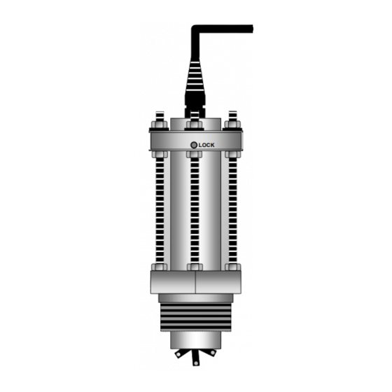
- Page 1 BI-DIRECTIONAL INSERTION METER INSTRUCTION MANUAL LOCK...
-
Page 2: Table Of Contents
Contents CONTENTS PAGE INTRODUCTION General arrangement Overview Operating principal Specifications INSTALLATION Meter location Meter installation & orientation Height adjustment Flow direction orientation Hot tap installations ELECTRICAL CONNECTIONS Standard outputs Voltage Pulse / Hall Effect Optional Hall Effect / Reed switch output Optional Reed switch output Instrument cable installation requirements Pulse output selection ( standard outputs ) -
Page 3: Introduction
Introduction General arrangement Thank you for purchasing this Insertion Meter. It is important that you read this manual to gain a full understanding of the capability and operational aspects of the equipment you are about to install. This information is provided only to assist in the installation of the product and does not diminish your obligation to read the manual. -
Page 4: Overview
Introduction Overview The Insertion Meter provides a cost effective and simple means of measuring the flow of a wide range of low viscosity liquids. Installation is quick and inexpensive for pipe diameters ranging from 40mm to 900mm (1.5-36") and up to 2500mm (100") nominal bore for the Hot tap capable model DP525. -
Page 5: Installation
Installation 2.1 Meter location Choose an appropriate section of horizontal or vertical pipe as per the guidelines below. With vertical pipe installations the media should be pumped up through the pipe past the flow sensor so that any entrained air will pass freely. The Insertion Meter requires a fully developed turbulent flow profile to ensure maximum measurement accuracy and repeatability. -
Page 6: Height Adjustment
Installation 2.3 Height adjustment calculation Calculate the adjustment height A for DP490 (or AA for the DP525) as follows: ( for DP490 ) = 175mm ( 6.9") - ( B + C + D ) AA ( for DP525 ) = 420mm (16.5") - ( B + C + D ) Where : B = Distance between the top of the pipe &... -
Page 7: Hot Tap Installations
Installation 2.5 Hot tap installation IMPORTANT ( model DP525 ) Before removing the DP525 from the installation first withdraw the Clean & lubricate screw Meter body to threads before the maximum withdrawing the Meter distance allowed by body in order to avoid the three height nut seizure adjusting threaded... -
Page 8: Electrical Connections
Electrical Standard Outputs ELECTRICAL CONNECTIONS ( see page 10 for QP outputs ) 3.1 Standard outputs – NPN Hall Effect + Voltage Pulse outputs Conductor color coding also applies to the Non-magnetic sensor and high temperature output options Pull up resistor required, they are generally incorporated in most receiving... -
Page 9: Optional Hall Effect / Reed Switch Output
Electrical connections 3.2 Optional – NPN Hall Effect + Reed Switch outputs Conductor color coding also applies to the Non-magnetic sensor and high temperature output options Pull up resistor required, they are generally incorporated in most receiving instruments Positioning collar Height adjustment LOCK... -
Page 10: Instrument Cable Installation Requirements
Electrical connections 3.4 Instrument cable installation requirements Use twisted multi-core low capacitance shielded instrument cable (22 AWG ~ 7x 0.3 stranded) for electrical connection between the Insertion Meter and the remote instrumentation. The screen should be earthed at the readout instrument end only to protect the transmitted signal from mutual inductive interference. -
Page 11: Qp Quadrature Pulse Output Option
Electrical connections 3.6 Quadrature outputs Insertion Meters supplied with the QP option produce two NPN open collector pulse outputs from two Hall Effect sensors. The outputs are “ phase offset ” in their timing so that external electronics are able to differentiate. These outputs may be used to assure output signal integrity or to measure bi-directional flow. -
Page 12: Connection To Family Instruments
Electrical connections 3.8 Voltage Pulse Connection to family instruments Note: For other output styles see receiving instrument manual RATE TOTALISER RATE TOTALISER RUN ACCUM. TOTAL STOP BAT LOW & ECOBATCH INSTRUMENTS RESET ACCUM PROGRAM yellow > ENTER TOTAL DIP switches all in the RATE TOTAL... -
Page 13: Calibration ( K- Factor For Meter )
Calibration K – FACTORS ( calibration factors for meter ) The K-factor (pulses / litre, gallon etc.) will vary in relation to the bore size of the pipe in which the Insertion Meter is installed. The K-factors and formula shown are a result of factory testing using smooth bore piping under ideal conditions. -
Page 14: Calculating K-Factors ( Metric Units - Litres Or M3 )
Calibration 4.3 Calculating K-factors ( litres or m³ ) 24.5 Pipe ID 450mm & above (A) = 22.5 23.5 example a 22.5 80 100 120 140 160 180 200 220 240 260 280 300 320 340 360 380 400 420 440 460 pipe ID (mm) Calculate K-factor ( pulses / litre ) using the above graph and the metric constant of 1273.2 as... -
Page 15: Calculating K-Factors ( Us Gallons )
Calibration 4.4 Calculating K-factors ( US gallons ) Pipe ID 19.5 ” & above (A) = 6.86 pipe ID (inches) Calculate K-factor ( pulses / gallon ) using the above graph and the volumetric constant of 24.51 as follows : Pulses / US gal. -
Page 16: Installation Guidelines
Installation Guidelines 5.0 INSTALLATION GUIDELINES GENERAL The flow profile must be uniform at the point where the Insertion Meter is to be installed, otherwise inaccurate and unstable readings will result. British Standard: BS 1042 gives a full insight into flow conditioning for inferential flow devices The general rule is to have a minimum of 10 diameters of straight pipe runs before the flowmeter (upstream) and 5 diameters after (downstream). -
Page 17: Installation Guidelines
Installation Guidelines 3. PRECAUTIONS FOR AVOIDING NON-UNIFORM FLOW 4. RECOMMENDED LENGHTS OF STRAIGHT PIPE FOR TYPICAL CASES RECOMMENDED SOLUTIONS FOR RESTRICTED CASES... - Page 18 NOTES:...
- Page 19 NOTES:...
- Page 20 © 2017 Great Plains Industries, Inc., All Rights Reserved. Great Plains Industries, Inc. / 888-996-3837 / FLOMEC.net IM-DP-1716...
Need help?
Do you have a question about the 490 and is the answer not in the manual?
Questions and answers