Table of Contents
Advertisement
Quick Links
Each meter has been calibrated on mineral oil
and will contain a small amount of oil residue.
The oil used is Castrol Diesel Calibration
Fluid 4113 (product code 055830).
Flomec Factory
1 / 19 Northumberland Road,
Caringbah NSW 2229, Sydney
AUSTRALIA
tel : +61 2 9540 4433
fax : +61 2 9525 9411
email :
sales@flomec.com.au
website :
www.flomec.com.au
USA
916 Belcher Drive
Pelham, AL 35124
USA
Tel : +1 205 378 1050
Fax : +1 205 685 3001
Email :
customerservice@trimecus.com
Website : www.trimecus.com
IMOMMED-0907
I
M
P
O
R
T
A
N
T
Distributed by:
OVAL GEAR
SEE OVER
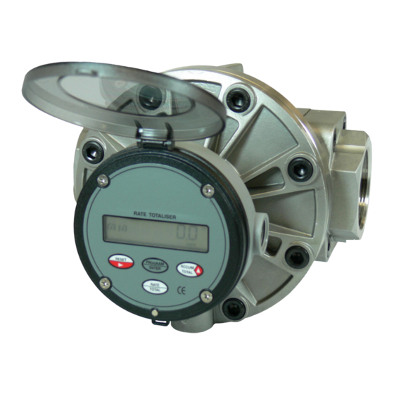
Medium capacity positive displacement flowmeters
I N S T R U C T I O N M A N U A L
Models : OM025, OM040 & OM050
Advertisement
Table of Contents


Need help?
Do you have a question about the OM025 and is the answer not in the manual?
Questions and answers