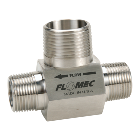
Flomec G Series Owner's Manual
Industrial and chemical models
Hide thumbs
Also See for G Series:
- Product owners manual (20 pages) ,
- Product owners manual (20 pages)
Subscribe to Our Youtube Channel
Summary of Contents for Flomec G Series
- Page 1 SAVE THESE INSTRUCTIONS G SERIES TURBINES (Industrial and Chemical Models) Owner’s Manual 06/15 921977-01C...
-
Page 2: Table Of Contents
Our business is the design, manufac- your G Series Turbine. If you need as- ture, and marketing of liquid handling, sistance, contact the distributor from agricultural, and recreational prod- whom you purchased your turbine. -
Page 3: Installation
This is extremely important when 3. Check the interconnection cable sizing a turbine flowmeter where between the turbine flowmeter and the volume is measured per hour or readout device. Refer to Checking per day. For example, an application the Cable Assembly section. where the total output is 500 barrels 4. -
Page 4: Maintenance
will cause the rotor to spin at a faster MAINTENANCE rate than liquid, thus resulting in in- correct readings, which results in an Disassembling the Turbine overstatement of actual flowrate and volume. This condition can damage 1. Disconnect the turbine flowmeter the flowmeter. - Page 5 The body bore should be smooth NOTE: FLOMEC rotors are tapered on and show no evidence of wear. one end (except ½" and ¾"). The NOTE: Do not install a new replace-...
- Page 6 Figure 2 Standard Design Replacement Kit (Industrial & Chemical) ROTOR ASSEMBLY F L O W ➞ ROTOR SUPPORT RETAINING FLUSH FLUSH RETAINING ASSEMBLIES RING HOLE HOLE RING Replacement Kits for Industrial Turbine Flowmeters Tungsten Carbide* High Density Plastic* Flow Range Size Model Part No.
- Page 7 Electronics netic pickups: Standard and Wire can be either Local or Remote. Remote Lead. See Figure 3. electronics include FLOMEC Remote Displays or output to customer supplied Figure 3 equipment. Follow the next three steps when choosing a magnetic pickup.
- Page 8 Magnetic Pickup Enclosures is the weatherproof enclosure. For explosion-proof enclosures, choose Pickup Enclosures are optional on G N7A for the enclosure without the Series Turbine Meters. Choose from terminal strip or the N7AT with the three pickup enclosures: Model N4A terminal strip.
- Page 9 FLOW RANGES Gallons Per Minute Litres Per Minute Size Min. Max. Min. Max. Frequency Output ½ in. 100 - 1000 Hz ½ in. 125 - 1000 Hz ¾ in. 100 - 1000 Hz ¾ in. E 100 - 1000 Hz 1 in.
-
Page 10: Troubleshooting
then the magnetic pickup is good and TROUBLESHOOTING should NOT be replaced. If the ohm meter reads less than 1000 ohms, Locating the Problem install a new magnetic pickup. DO NOT throw the old magnetic pickup To determine the location of the away. - Page 11 flowmeter parts are free from any will eliminate the possibility of using foreign matter, reassemble. and/or discarding a turbine flowmeter which shows signs of wear. NOTE: Always ensure that a sup- port vane is installed between the NOTE: A good turbine flowmeter body indention marks on the body.
- Page 12 When the frequency oscillator is con- it to the electronic readout device, the same as you would a turbine nected and an output is displayed on flowmeter cable assembly. Once the the electronic readout device, this indi- frequency oscillator is connected, if no cates that the turbine flowmeter cable output is displayed on the electronic assembly is defective and should be...
-
Page 13: Specifications
Standard Materials of SPECIFICATIONS Construction Accuracy*: ±0.5% of the true flow at Housing: 316 Stainless Steel any point within the linear range of the turbine flowmeter. Rotor: CD4MCu Stainless Steel Linearity*: ±0.5% of the mean K- Shaft: Tungsten Carbide (standard), factor throughout the linear range. - Page 14 Pressure Drop vs. Flowrate Flowrate Gallons Per Minute For estimating pressure drops on liquids other than water, use the following formulas: P = [ VISC (CPS) ] 1/4 x [ S.G. ] ¾ [ PH O ] Where: CPS = Absolute Viscosity in Centipoise = Specific Gravity PH O = Pressure Drop at the Operating Flowrate from the Chart 921977-01C...
-
Page 15: Service
Returning Parts SERVICE Please contact GPI before return- For warranty consideration, parts, ing any parts. It may be possible to or other service information, please diagnose the trouble and identify contact your local distributor. If you needed parts in a telephone call. GPI need further assistance, call the GPI can also inform you of any special Customer Service Department during... - Page 16 Note: In compliance with MAGNUSON MOSS CONSUMER WARRANTY ACT – Part 702 (governs the resale availability of the warranty terms). © 2015 GREAT PLAINS INDUSTRIES, INC. All Rights Reserved. and FLOMEC are registered trademarks of Great Plains Industries, Inc. 06/15 921977-01C...


Need help?
Do you have a question about the G Series and is the answer not in the manual?
Questions and answers