Rohde & Schwarz EVSG1000 User Manual
Vhf/uhf airnav/com analyzer
Hide thumbs
Also See for EVSG1000:
- Getting started (52 pages) ,
- User manual (418 pages) ,
- Getting started (51 pages)
Table of Contents
Advertisement
Quick Links
Advertisement
Chapters
Table of Contents

Related Manuals for Rohde & Schwarz EVSG1000


Summary of Contents for Rohde & Schwarz EVSG1000
- Page 1 ® R&S EVSG1000 VHF/UHF Airnav/Com Analyzer User Manual (;ÜÌK2) 1178622702...
- Page 2 ® This document describes the following R&S EVSG1000 models with firmware version 1.20 and later: ● ® R&S EVSG1000 (1329.8009.02) Furthermore, it covers the following options: ● ® R&S EVSG-B1 Second Signal Proc. Unit (1329.8809.02) ● ® R&S EVSG-B2 Battery Management (1329.8815.02) ●...
-
Page 3: Table Of Contents
Connecting an External DC Power Source..............15 2.2.3.3 Using an Optional Battery Pack (R&S EVSG-B3)............16 2.2.4 Connecting Devices for Signal Input and Output............17 2.2.5 Switching the R&S EVSG1000 On and Off..............17 Instrument Tour......................18 2.3.1 Front Panel........................18 2.3.2 Rear Panel........................22 2.3.3... - Page 4 ® Contents R&S EVSG1000 3 Measurements and Results..............36 4 Configuring the Input Signal and Measurement Mode.....39 Input Signal Settings....................39 Receiver Board......................40 Measurement Mode.....................41 5 Numeric Measurement Modes............42 ILS Localizer and ILS Glidepath (GP) Modes............42 5.1.1 Localizer Basics......................42 5.1.2...
- Page 5 ® Contents R&S EVSG1000 5.2.3.3 Setting the Measurement Time (MTime)............... 72 VOR Mode (Option R&S EVSG-K2)................73 5.3.1 VOR Basics........................73 5.3.1.1 VHF Omni Directional Radio Range (VOR)..............73 5.3.1.2 VOR Demodulator......................76 5.3.1.3 Phase Notation in VOR Measurements................ 78 5.3.2 VOR Measurements and Results..................79 5.3.2.1...
- Page 6 ® Contents R&S EVSG1000 6.1.2 Configuring the Bandwidth..................102 6.1.3 Configuring the Amplitude (Y-Axis)................103 6.1.4 Configuring the Trace....................104 IF Spectrum Mode (Option R&S EVSG-K10)............105 6.2.1 Configuring the Frequency Range................106 6.2.2 Configuring the Bandwidth..................107 6.2.3 Configuring the Amplitude (Y-Axis)................107 6.2.4...
- Page 7 ® Contents R&S EVSG1000 7.3.3.2 Slot Results Table....................... 134 7.3.4 Constellation View.......................135 7.3.5 Message View......................136 7.3.6 Recording View......................137 GBAS/ SCAT-I Measurement Configuration............139 7.4.1 View Configuration...................... 139 7.4.2 Frequency Configuration.....................140 7.4.3 Amplitude Configuration....................140 7.4.4 Bandwidth Configuration..................... 141 7.4.5 General Configuration....................141 Message XML Interface....................
- Page 8 ® Contents R&S EVSG1000 7.5.7.1 Fill Type........................161 8 Power Sensor Support (Option R&S EVSG-K24)......162 9 Using Markers in the Graphical Displays........164 10 Data Management................166 10.1 Storing and Recalling Measurement Settings (Preset)......... 166 10.1.1 Storage and Recall Functions..................166 10.2...
- Page 9 ® Contents R&S EVSG1000 13.1.9 Calibration........................215 13.1.10 Network Settings and Remote Operation..............216 13.1.11 Deprecated Commands....................218 13.2 ILS Localizer (LOC) and Glidepath (GP) Modes............. 219 13.2.1 Configuring the ILS LOC and GP Modes..............220 13.2.2 Configuring ILS Localizer Measurements..............220 13.2.3...
- Page 10 ® Contents R&S EVSG1000 13.9.2 Retrieving AF Spectrum Results................. 275 13.10 AF Time Domain Mode....................275 13.10.1 Configuring AF Time Domain Measurements............. 275 13.10.2 Retrieving RF Spectrum Results.................278 13.11 Data Management..................... 278 13.11.1 Data Recording......................279 13.11.2 Data Streaming......................283 13.11.3 Results for Data Streaming..................
-
Page 11: Preface
1.2.1 Getting Started Manual Introduces the R&S EVSG1000 and describes how to set up and start working with the product. A printed version is delivered with the instrument. 1.2.2 User Manuals and Help Contains the description of all instrument modes and functions. -
Page 12: Basic Safety Instructions
The printed document is delivered with the instrument. 1.2.4 Data Sheets and Brochures The data sheet contains the technical specifications of the R&S EVSG1000. It also lists the firmware applications and their order numbers, and optional accessories. The brochure provides an overview of the instrument and deals with the specific char- acteristics. -
Page 13: Getting Started
R&S EVSG1000 Preparing for Use 2 Getting Started 2.1 Key Features The R&S EVSG1000 offers the following key features: ● Detailed analysis of ILS, VOR and Marker Beacon ground measurements (based on ICAO Doc. 8071 and ICAO Annex 10) ●... -
Page 14: Setting Up The Instrument
Printed Getting Started manual 2.2.2 Setting Up the Instrument The R&S EVSG1000 can be operated in a variety of places without detrimental effects on its features. Even the movement caused by transportation or mobile use does not impair its functioning. -
Page 15: Connecting The Power Supply
DC power sources. Risk of instrument damage due to excess voltage The R&S EVSG1000 must be operated only on DC power with a voltage of 10 V DC to 28 V DC and a current of 3.0 A. The provided DC power supply unit must only be plugged into a two-pin grounded socket! Use the provided AC/DC power supply unit to operate the R&S EVSG1000 on a 230 V... -
Page 16: Using An Optional Battery Pack (R&S Evsg-B3)
2.2.3.3 Using an Optional Battery Pack (R&S EVSG-B3) As an alternative to the fixed AC or DC power supply, the R&S EVSG1000 can be operated by a battery pack if the R&S EVSG-B2 and R&S EVSG-B3 options are instal- led. If the battery pack is installed and no DC power is supplied, the R&S EVSG1000 automatically switches to battery operation (during operation). -
Page 17: Connecting Devices For Signal Input And Output
12 V DC, the internal battery is charged regardless whether the instrument is switched on or off. Starting Process The boot process of the R&S EVSG1000 takes about 30 seconds. Then the instru- ment automatically starts the measurement mode used before the instrument was switched off. -
Page 18: Instrument Tour
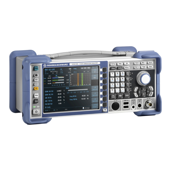
10 = Keypad 11 = Rotary Knob 12 = Navigation keys Power Key The [Power] key starts up and shuts down the R&S EVSG1000. Display The TFT color display shows all measurement and configuration details. RX1 IN / RX 2 IN Use the RX inputs to connect a receiving antenna (max. - Page 19 ® Getting Started R&S EVSG1000 Instrument Tour "RX 2 In" is supplied as an option (R&S EVSG-B1). This option allows you to perform two independent measurements simultaneously, for example on different frequencies. This capability is vital in flight inspection systems because localizer and glidepath signals must be measured at the same time.
- Page 20 ® Getting Started R&S EVSG1000 Instrument Tour tion key is also called a menu. Softkeys can either perform a specific function or open a dialog box. Function Keys Function keys provide access to the most common measurement settings and func- tions.
- Page 21 ® Getting Started R&S EVSG1000 Instrument Tour Type of key Description Closes all kinds of dialog boxes, if the edit mode is not active. Quits the edit mode, if the edit mode is active. In dialog boxes that contain a "Cancel" but- ton it activates that button.
-
Page 22: Rear Panel
Demod Out Outputs a demodulated signal for connected devices, for example an oscilloscope LF In BNC socket, 50 Ω/20kΩ to input a baseband signal to the R&S EVSG1000 for further analysis of typical AF parameters User Manual 1178.6227.02 ─ 04... -
Page 23: Accessories
2-port, 9-pin Sub-D connector for a GPS receiver providing NMEA protocol data. The NMEA protocol data is displayed and stored with the recorded data. Through the LAN connection (Fast Ethernet), all functions of the R&S EVSG1000 can be remotely operated. The LAN connection can also be used to stream measurement data. - Page 24 ® Getting Started R&S EVSG1000 Instrument Tour Figure 2-3: Weather protection bag ● Rugged Transport case (R&S EVSG-Z2) It is a hard-top case with trolley functionality. Figure 2-4: Transport Case ● ILS / VOR Dipole Antenna (R&S EVS-Z3) The lightweight design of the ILS/VOR dipole antenna and its compact size makes this antenna ideal for mobile measurements in the field.
- Page 25 ® Getting Started R&S EVSG1000 Instrument Tour Figure 2-5: ILS / VOR Dipole Antenna ● Antenna bag (R&S EVS-Z4) The carrying bag allows you to transport all the antenna elements and the tele- scopic mast safely. Figure 2-6: Antenna bag ●...
-
Page 26: Operating Basics
Operating Basics ● 19''-adapter (R&S EVSG-Z7) This option is required for the mounting of the R&S EVSG1000 in a 19'' rack (e.g. in a measurement vehicle). 2.4 Operating Basics The R&S EVSG1000 is designed for ground inspection and is thus optimized for man- ual operation, via the graphical user interface. - Page 27 "2/2" beneath the softkeys in the display. To switch between the two menus of softkey functions, press the "More softkeys" key beneath the softkeys on the front panel of the R&S EVSG1000. Softkeys can perform a function directly, or open a dialog or submenu with further set- tings and functions.
-
Page 28: Manual Operation
2.4.2.1 Changing Settings and Activating Functions All functions available on the R&S EVSG1000 can be accessed using the keys on the front panel of the instrument. Some keys provide a softkey menu on the display with further functions and settings. - Page 29 If a field requires alphanumeric input, use the keypad on the front panel of the R&S EVSG1000. Every alphanumeric key represents several characters and one num- ber. The decimal point key (.) represents special characters, and the sign key (-) tog- gles between capital and small letters.
-
Page 30: Getting Help
<toggles between capital and small letters> 2.4.2.3 Getting Help If any questions or problems concerning the R&S EVSG1000 arise, an online help sys- tem is provided on the instrument and can be consulted at any time. Displaying the online help system on the instrument 1. - Page 31 ® Getting Started R&S EVSG1000 Operating Basics 2. Press [Enter] to display the user manual contents. User Manual 1178.6227.02 ─ 04...
-
Page 32: Manual Operation From A Vnc Viewer
► Press [ESC]. 2.4.3 Manual Operation from a VNC Viewer As an alternative to operating the R&S EVSG1000 directly on the instrument, you can perform the same tasks from a connected PC using a keyboard. You merely require a VNC viewer application, of which a variety is available on the Internet free of charge. - Page 33 Using a VNC viewer application, you simply connect to the instrument, defined by its IP address. The display of the R&S EVSG1000 is shown on the control PC. The keys and other graphical user interface elements are operated using associated keyboard short- cuts on the connected keyboard.
-
Page 34: Remote Control
Record Marker 2.4.4 Remote Control You can control the R&S EVSG1000, including data transfer, remotely from a PC using the LAN connection (Fast Ethernet). You define the IP address and subnet mask in the "Setup" menu. User Manual 1178.6227.02 ─ 04... - Page 35 Operating Basics Remote control is performed using predefined remote commands which are sent from the control PC to the R&S EVSG1000. The R&S EVSG1000 can also return queried data to the control PC. For details on the available remote commands, see Chapter 13, "Remote...
-
Page 36: Measurements And Results
R&S EVSG1000 3 Measurements and Results The R&S EVSG1000 provides both numerical and graphical results, depending on the current measurement task. Different measurement tasks are performed in individual measurement modes, some of which are optional. The individual measurement modes are described in detail in the subsequent chapters of this documentation. - Page 37 ® Measurements and Results R&S EVSG1000 ● COM (R&S EVSG-K6) - determines signal parameters from VHF/UHF communica- tion channels Measurement modes with graphical results The following measurement modes provide graphical results: ● RF Spectrum mode (R&S EVSG-K10) - displays the power vs. frequency diagram (spectrum) for a variable frequency range of the input signal ●...
- Page 38 ® Measurements and Results R&S EVSG1000 RX board (RX1 | RX2) The currently active receiver board. See Chapter 4.2, "Receiver Board", on page 40. Measurement mode The currently active measurement mode on the active receiver board, e.g. "ILS LOC". Chapter 4.3, "Measurement Mode",...
-
Page 39: Configuring The Input Signal And Measurement Mode
Configures the source for receiver 1. "RX 1 In" The RX 1 In connector on the front of the R&S EVSG1000 is connec- ted to a receiving antenna (max. +13 dBm). The antenna must corre- spond to the specified frequency range for the measurement. -
Page 40: Receiver Board
Configures the source for RX 2. (Only available with option R&S EVSG-B1.) "RX 2 In" Through the RX 2 In input on the front of the instrument, the R&S EVSG1000 is connected with a second receiving antenna (max. +13 dBm) corresponding to the frequency range. "LF In"... -
Page 41: Measurement Mode
® Configuring the Input Signal and Measurement Mode R&S EVSG1000 Measurement Mode Remote command: on page 196 4.3 Measurement Mode The measurement mode determines the type of signal for which the measurement is performed (see Chapter 3, "Measurements and Results", on page 36). -
Page 42: Numeric Measurement Modes
® Numeric Measurement Modes R&S EVSG1000 ILS Localizer and ILS Glidepath (GP) Modes 5 Numeric Measurement Modes ● ILS Localizer and ILS Glidepath (GP) Modes............42 ● ILS Marker Beacon Mode (Option R&S EVSG-K3)..........63 ● VOR Mode (Option R&S EVSG-K2)............... -
Page 43: Glide Slope Basics
® Numeric Measurement Modes R&S EVSG1000 ILS Localizer and ILS Glidepath (GP) Modes ● The signal strength from both beams is equal: the aircraft is in the center, on the right course. Course and clearance signals The landing path is divided into the region further away from the runway, referred to as the course, and the runway itself, referred to as the clearance. -
Page 44: Ils Localizer And Glidepath Measurements And Results
A predominant 150 Hz means that the aircraft is too low and needs to climb. 5.1.3 ILS Localizer and Glidepath Measurements and Results A single receiver board in the R&S EVSG1000 can measure data at two different receiver frequencies at the same time. Therefore, the ILS Localizer and Glidepath measurements can detect both course and clearance data simultaneously, and display the individual results. -
Page 45: Rf Level And Frequency Display
® Numeric Measurement Modes R&S EVSG1000 ILS Localizer and ILS Glidepath (GP) Modes formed to obtain an initial overview of the input signal and determine the basic signal characteristics. The displayed measurement results depend on the selected channel and frequency configuration. -
Page 46: If Spectrum Preview
® Numeric Measurement Modes R&S EVSG1000 ILS Localizer and ILS Glidepath (GP) Modes ● Measured frequency offset to the nominal frequency in kHz ● Numeric frequency offset of measured power ● Numeric power sensor level in dBm (if available; "NRP") ●... -
Page 47: Ils Localizer And Glidepath Main View
® Numeric Measurement Modes R&S EVSG1000 ILS Localizer and ILS Glidepath (GP) Modes Figure 5-3: IF spectrum preview This preview spectrum allows you to check if the current measurement settings are appropriate, such as the bandwidth or frequency offsets. For a larger, more detailed spectrum diagram, select one of the graphical Spectrum modes. - Page 48 ® Numeric Measurement Modes R&S EVSG1000 ILS Localizer and ILS Glidepath (GP) Modes Figure 5-5: ILS Glidepath Main view 90-150........................48 90,150........................48 AM 90 Hz........................49 Freq 90 Hz........................49 AM 150 Hz........................49 Freq 150 Hz........................49 Code......................... 49 90/150........................
-
Page 49: Ils Localizer Distortion View
® Numeric Measurement Modes R&S EVSG1000 ILS Localizer and ILS Glidepath (GP) Modes Remote command: on page 235 on page 235 on page 235 SCLR on page 235 SCRS AM 90 Hz AM modulation depth of 90 Hz ILS component... - Page 50 ® Numeric Measurement Modes R&S EVSG1000 ILS Localizer and ILS Glidepath (GP) Modes Figure 5-6: ILS Localizer Distortion view AM 90 Hz........................50 K2 90 Hz........................50 K3 90 Hz........................51 K4 90 Hz........................51 THD 90 Hz........................51 Res. FM 90........................51...
- Page 51 ® Numeric Measurement Modes R&S EVSG1000 ILS Localizer and ILS Glidepath (GP) Modes Remote command: on page 233 K2_90 K3 90 Hz Distortion 3 order, 90 Hz signal Remote command: on page 233 K3_90 K4 90 Hz Distortion 4 order, 90 Hz signal...
-
Page 52: Ils Localizer Id Analysis View
® Numeric Measurement Modes R&S EVSG1000 ILS Localizer and ILS Glidepath (GP) Modes K4 150 Hz Relative amplitude of the fourth harmonic for the 150 Hz signal component Remote command: on page 234 K4_150 THD 150 Hz Total Harmonic Distortion (THD) for the 150 Hz signal component... - Page 53 ® Numeric Measurement Modes R&S EVSG1000 ILS Localizer and ILS Glidepath (GP) Modes Figure 5-7: ID Analysis view 90-150........................53 Last ID...........................53 Code......................... 54 Period........................54 Length........................54 Dash Length........................54 Dot-Dash Gap....................... 54 Letter Gap........................54 AM..........................54 Freq.......................... 54 DDM 90-150...
- Page 54 ® Numeric Measurement Modes R&S EVSG1000 ILS Localizer and ILS Glidepath (GP) Modes Remote command: on page 237 LASTID_TIME ID Code Morse-decoded ID with three or four letters. Remote command: on page 230 on page 248 ID Period Time between two measured ID pulses...
-
Page 55: Ils Localizer Recording View
® Numeric Measurement Modes R&S EVSG1000 ILS Localizer and ILS Glidepath (GP) Modes 5.1.3.6 ILS Localizer Recording View The Recording view displays the recorded data for ILS Localizer measurements from the selected data list (see "List" on page 170). If available, the stored GPS data from the GPS receiver is also displayed. -
Page 56: Channel And Frequency Configuration
® Numeric Measurement Modes R&S EVSG1000 ILS Localizer and ILS Glidepath (GP) Modes Settings for recording, including trigger settings, are described in Chapter 10.2, "Recording Measurement Data", on page 168. ● Channel and Frequency Configuration..............56 ● Ampt........................59 ● Bandwidth (BW)...................... -
Page 57: Carrier Configuration (1F/2F Config)
® Numeric Measurement Modes R&S EVSG1000 ILS Localizer and ILS Glidepath (GP) Modes "2F CLR" Both the course and clearance frequencies are measured simultane- ously. The results for both frequencies, as well as the sum of both, are displayed in the RF Level display. Both frequencies are displayed in the RF Spectrum preview. -
Page 58: Channel Frequency Configuration (Ch Freq)
® Numeric Measurement Modes R&S EVSG1000 ILS Localizer and ILS Glidepath (GP) Modes Course Defines the course carrier as a frequency offset from the nominal frequency. Clearance Defines the clearance carrier as a frequency offset from the nominal frequency in the opposite direction to the course carrier. -
Page 59: Ampt
® Numeric Measurement Modes R&S EVSG1000 ILS Localizer and ILS Glidepath (GP) Modes quencies. (See Chapter A, "ILS Channel Frequency List", on page 291 and Chapter B, "VOR Channel Frequency List", on page 293.) CH..........................59 Freq..........................59 Step Size........................59 Sets the receiver frequency channel on the active receiver board according to the ICAO frequency list. -
Page 60: Bandwidth (Bw)
When monitoring signals with mostly constant signal levels, it is also recommended that you use the "Low Noise", "Normal" or "Low Distor- tion" mode. If the R&S EVSG1000 has to adapt the attenuation frequently, indica- ted by a frequent clicking noise from the attenuator, spikes can occur in the trace. - Page 61 ® Numeric Measurement Modes R&S EVSG1000 ILS Localizer and ILS Glidepath (GP) Modes Access VNC: [e] The bandwidth determines the frequency range for which the measurement is per- formed. Depending on the measurement mode, and whether a wideband or a specific frequency is measured, different settings are available.
-
Page 62: Setting The Measurement Time (Mtime)
® Numeric Measurement Modes R&S EVSG1000 ILS Localizer and ILS Glidepath (GP) Modes Res. FM Filt. (ILS only) Defines the filter type used to determine residual FM (see Chapter 5.1.3.4, "ILS Local- izer Distortion View", on page 49). "ICAO" Filter according to ICAO specification "Narrow"... -
Page 63: Ils Marker Beacon Mode (Option R&S Evsg-K3)
® Numeric Measurement Modes R&S EVSG1000 ILS Marker Beacon Mode (Option R&S EVSG-K3) Remote command: on page 200 SETUP:UNIT:SDM ILS Phase Specifies the value range in the ILS phase. Bipolar: -60 … +60° | Unipolar: 0 … 120° Remote command:... -
Page 64: Ils Marker Beacon Measurements And Results
® Numeric Measurement Modes R&S EVSG1000 ILS Marker Beacon Mode (Option R&S EVSG-K3) Figure 5-9: Marker beacon placement with respect to runway Marker beacon receivers decode audio and provide signaling output to identify one of three marker beacons installed near the runway. They transmit a narrow beam width at 75 MHz carrier frequency in a vertical direction. -
Page 65: Rf Level And Frequency Display
® Numeric Measurement Modes R&S EVSG1000 ILS Marker Beacon Mode (Option R&S EVSG-K3) You can display graphical results directly from the ILS Marker Beacon mode by select- ing the softkey in the "Meas" menu. In this case, the settings for the current measure- ment are applied to the graphical results. -
Page 66: If Spectrum Preview
® Numeric Measurement Modes R&S EVSG1000 ILS Marker Beacon Mode (Option R&S EVSG-K3) – green: power in a valid range ● If applicable: overload messages Overload messages The following messages indicate an overload: ● "RF Overload" Overload of the input mixer or of the analog IF path. -
Page 67: Ils Marker Beacon Main View
® Numeric Measurement Modes R&S EVSG1000 ILS Marker Beacon Mode (Option R&S EVSG-K3) This preview spectrum allows you to check if the current measurement settings are appropriate, such as the bandwidth or frequency offsets. For a larger, more detailed spectrum diagram, select one of the graphical Spectrum modes. If you switch to such a mode directly from a numeric measurement mode, the current measurement settings are applied to the spectrum automatically. -
Page 68: Ils Marker Beacon Id Analysis
® Numeric Measurement Modes R&S EVSG1000 ILS Marker Beacon Mode (Option R&S EVSG-K3) AM 1300 Hz AM modulation depth of the 1300-Hz component Remote command: on page 243 Freq 1300 Hz Measured frequency of the 1300-Hz component Remote command: on page 242... - Page 69 ® Numeric Measurement Modes R&S EVSG1000 ILS Marker Beacon Mode (Option R&S EVSG-K3) 400 Hz Dash......................... 69 400 Hz Gap........................69 1300 Hz Dash....................... 69 1300 Hz Dot........................69 1300 Hz Gap......................... 69 3000 Hz Dot........................69 3000 Hz Gap......................... 69 400 Hz Dash Displays the length of a dash for the outer marker (in ms).
-
Page 70: Ils Marker Beacon Recording View
® Numeric Measurement Modes R&S EVSG1000 ILS Marker Beacon Mode (Option R&S EVSG-K3) 5.2.2.5 ILS Marker Beacon Recording View The Recording view displays the recorded data for ILS Localizer measurements from the selected data list (see "List" on page 170). If available, the stored GPS data from the GPS receiver is also displayed. -
Page 71: Setting The Receiver Frequency
® Numeric Measurement Modes R&S EVSG1000 ILS Marker Beacon Mode (Option R&S EVSG-K3) 5.2.3.1 Setting the Receiver Frequency Access: [CH FREQ] Access VNC: [q] The receiver frequency determines the nominal frequency at which the measurement is performed. Freq..........................71 Step Size........................71 Freq Sets the nominal frequency for the measurement. -
Page 72: Setting The Measurement Time (Mtime)
When monitoring signals with mostly constant signal levels, it is also recommended that you use the "Low Noise", "Normal" or "Low Distor- tion" mode. If the R&S EVSG1000 has to adapt the attenuation frequently, indica- ted by a frequent clicking noise from the attenuator, spikes can occur in the trace. -
Page 73: Vor Mode (Option R&S Evsg-K2)
5.3 VOR Mode (Option R&S EVSG-K2) Access: [Mode] > "VOR" Access VNC: [m] > Down arrow key If the VOR Mode option (R&S EVSG-K2) is installed, signals from VOR systems can be analyzed with the R&S EVSG1000. Remote command: on page 246 MODE_VOR 5.3.1 VOR Basics... - Page 74 ® Numeric Measurement Modes R&S EVSG1000 VOR Mode (Option R&S EVSG-K2) Ground transmitter The transmitter stations operate at VHF frequencies of 108 MHz to 118 MHz, with the code identification (COM/ID) transmitting on a modulation tone of 1.020 kHz. It emits two types of signals: ●...
- Page 75 ® Numeric Measurement Modes R&S EVSG1000 VOR Mode (Option R&S EVSG-K2) nal Information Service) messages. The Morse code can be used to identify the VOR station, similar to the "Morse code identification signal" on page 43 in the ILS signal.
-
Page 76: Vor Demodulator
® Numeric Measurement Modes R&S EVSG1000 VOR Mode (Option R&S EVSG-K2) 5.3.1.2 VOR Demodulator Figure 5-15: Block diagram of the VOR software demodulator User Manual 1178.6227.02 ─ 04... - Page 77 ® Numeric Measurement Modes R&S EVSG1000 VOR Mode (Option R&S EVSG-K2) The VOR signal contains three AM modulated components that must be separated in a first step: ● Rotational signal (30 Hz) ● Identification/voice part (300 Hz to 4 kHz) ●...
-
Page 78: Phase Notation In Vor Measurements
® Numeric Measurement Modes R&S EVSG1000 VOR Mode (Option R&S EVSG-K2) FM Modulation Depth The FM deviation Devia (typically 480 Hz) is calculated by estimating the magni- FM30 tude of the FM demodulated 30 Hz reference signal. Azimuth (Phase Difference at 30 Hz) The phases of both the 30 Hz FM and 30 Hz AM signal are estimated at exactly the same time instant. -
Page 79: Vor Measurements And Results
® Numeric Measurement Modes R&S EVSG1000 VOR Mode (Option R&S EVSG-K2) ● TO: North direction at the receiver/ aircraft To convert one notation to the other, use the following equation: Phase = Phase + 180 deg FROM 5.3.2 VOR Measurements and Results The VOR measurement provides multiple views for the measurement results. -
Page 80: If Spectrum Preview
® Numeric Measurement Modes R&S EVSG1000 VOR Mode (Option R&S EVSG-K2) The following results are provided: ● Numeric power level in dBm ("Lev") For measurements on two frequencies: individual and sum power levels ● Measured frequency offset to the nominal frequency in kHz ●... -
Page 81: Vor Main View
® Numeric Measurement Modes R&S EVSG1000 VOR Mode (Option R&S EVSG-K2) Figure 5-18: IF spectrum preview This preview spectrum allows you to check if the current measurement settings are appropriate, such as the bandwidth or frequency offsets. For a larger, more detailed spectrum diagram, select one of the graphical Spectrum modes. - Page 82 Hz........................ 82 Freq FM30........................83 Index........................83 Bearing (from) Phase between both 30-Hz signals (direction of the R&S EVSG1000 in relation to the ground station). Remote command: on page 249 AM 30 Hz AM modulation depth of 30 Hz AM rotational signal...
-
Page 83: Vor Distortion View
® Numeric Measurement Modes R&S EVSG1000 VOR Mode (Option R&S EVSG-K2) Remote command: on page 248 Freq FM30 AF frequency of the 30 Hz reference signal Remote command: on page 248 FM Index FM frequency deviation of 30 Hz subcarrier... -
Page 84: Vor Id Analysis View
® Numeric Measurement Modes R&S EVSG1000 VOR Mode (Option R&S EVSG-K2) "K4" Distortion 4 order "K5" Distortion 5 order Remote command: on page 250 SUBCARR_K2 on page 250 SUBCARR_K3 on page 250 SUBCARR_K4 on page 251 SUBCARR_K5 Subcarrier AM Distortion Measures the AM distortion of the subcarrier. - Page 85 Gap....................... 85 Letter Gap........................86 AM..........................86 Freq.......................... 86 Bearing (from) Phase between both 30-Hz signals (direction of the R&S EVSG1000 in relation to the ground station). Remote command: on page 249 Last ID Time since last ID pulse was measured...
-
Page 86: Vor Recording View
® Numeric Measurement Modes R&S EVSG1000 VOR Mode (Option R&S EVSG-K2) Remote command: on page 237 ID_DOTDASH_GAP Letter Gap Length of time that passes between two transmitted letters in the used Morse code in milliseconds. Remote command: on page 237... -
Page 87: Configuring Vor Measurements
® Numeric Measurement Modes R&S EVSG1000 VOR Mode (Option R&S EVSG-K2) Which measurement results are stored is described in the remote commands, see on page 283. GETDATADEF The individual measurement results are described in the other result views. For details on data logging see Chapter 10.2, "Recording Measurement... -
Page 88: Signal Direction
® Numeric Measurement Modes R&S EVSG1000 VOR Mode (Option R&S EVSG-K2) 5.3.3.1 Signal Direction Access: [Config] > "Direction" Access VNC: [s] > "F1" Signal Direction Defines the reference for phase notation (see Chapter 5.3.1.3, "Phase Notation in VOR Measurements", on page 78). -
Page 89: Ampt
When monitoring signals with mostly constant signal levels, it is also recommended that you use the "Low Noise", "Normal" or "Low Distor- tion" mode. If the R&S EVSG1000 has to adapt the attenuation frequently, indica- ted by a frequent clicking noise from the attenuator, spikes can occur in the trace. -
Page 90: Bandwidth (Bw)
® Numeric Measurement Modes R&S EVSG1000 VOR Mode (Option R&S EVSG-K2) "Low Noise" 15 dB pre-amplification Provides a high sensitivity. Suitable when scanning the area for dis- tant signals. "Norm" 0 dB Provides a normal sensitivity. "Low Dist" 15 dB attenuation Provides a low sensitivity. -
Page 91: Com Mode (Option R&S Evsg-K6)
Access VNC: [m] > Down arrow key If the COM Analysis option (R&S EVSG-K6) is installed, signals from VHF/UHF com- munication channels can be analyzed with the R&S EVSG1000. Very high frequency (VHF) and ultrahigh frequency (UHF) communication is used for air traffic control (ATC COM), for example. -
Page 92: Rf Level And Frequency Display
® Numeric Measurement Modes R&S EVSG1000 COM Mode (Option R&S EVSG-K6) ● RF Level and Frequency Display................92 ● IF Spectrum Preview....................93 ● COM Main View...................... 93 ● COM Recording View....................95 5.4.1.1 RF Level and Frequency Display The measured RF power and frequency of the input signal is displayed both numeri- cally and graphically. -
Page 93: If Spectrum Preview
® Numeric Measurement Modes R&S EVSG1000 COM Mode (Option R&S EVSG-K6) Remote commands to retrieve results: on page 193 on page 250 FMEAS on page 194 RFCH on page 255 GET_MEASFREQ on page 255 GET_TX1_MEASFREQ on page 255 GET_TX2_MEASFREQ on page 255... - Page 94 ® Numeric Measurement Modes R&S EVSG1000 COM Mode (Option R&S EVSG-K6) Figure 5-21: COM Main view You can display graphical results directly from the COM mode by selecting the softkey in the "Meas" menu. In this case, the settings for the current measurement are applied to the graphical results.
-
Page 95: Com Recording View
® Numeric Measurement Modes R&S EVSG1000 COM Mode (Option R&S EVSG-K6) Remote command: on page 256 GET_ONE_AMMOD on page 256 GET_TX1_AMMOD on page 256 GET_TX2_AMMOD AM Freq Displays the demodulated frequency of the 1 kHz AM test tone at the individual carrier frequencies and for both carriers together. -
Page 96: Com Configuration
® Numeric Measurement Modes R&S EVSG1000 COM Mode (Option R&S EVSG-K6) For details on data logging see Chapter 10.2, "Recording Measurement Data", on page 168. 5.4.2 COM Configuration In this view, the measurements settings available for the currently active mode, can be configured. -
Page 97: Ampt
® Numeric Measurement Modes R&S EVSG1000 COM Mode (Option R&S EVSG-K6) Upper Carrier........................ 97 Lower Carrier........................ 97 Offset........................97 Upper Carrier The two carriers are defined as offsets to either side of the nominal (center) frequency. This setting defines the upper carrier with a positive offset to the center frequency. - Page 98 When monitoring signals with mostly constant signal levels, it is also recommended that you use the "Low Noise", "Normal" or "Low Distor- tion" mode. If the R&S EVSG1000 has to adapt the attenuation frequently, indica- ted by a frequent clicking noise from the attenuator, spikes can occur in the trace.
-
Page 99: Bandwidth (Bw)
® Numeric Measurement Modes R&S EVSG1000 COM Mode (Option R&S EVSG-K6) on page 272 FTT_ATTMODE on page 268 IFSPECT_ATTMODE on page 257 GBAS:ATTMODE Transducer Correction Configures the level correction. The specified value is added to the measured power levels to compensate for an inherent offset by the measurement setup, for example the antenna. -
Page 100: Graphic Measurement Modes
® Graphic Measurement Modes R&S EVSG1000 RF Spectrum Mode (Option R&S EVSG-K10) 6 Graphic Measurement Modes ● RF Spectrum Mode (Option R&S EVSG-K10)............100 ● IF Spectrum Mode (Option R&S EVSG-K10)............105 ● AF Spectrum Mode (Option R&S EVSG-K11)............110 ● AF Time Domain Mode (Option R&S EVSG-K12)..........115... -
Page 101: Configuring The Frequency Range
® Graphic Measurement Modes R&S EVSG1000 RF Spectrum Mode (Option R&S EVSG-K10) Generally, each mode is configured individually. When you switch modes, the most recently defined settings for that mode are applied. However, graphical results can also be displayed directly from the measurement modes with numeric results. -
Page 102: Configuring The Bandwidth
® Graphic Measurement Modes R&S EVSG1000 RF Spectrum Mode (Option R&S EVSG-K10) Define the frequency range to be displayed using one of the following methods: ● Center + Span: the center frequency is displayed in the center of the x-axis, with half the span to the either side ●... -
Page 103: Configuring The Amplitude (Y-Axis)
Higher values decrease the preci- sion, but increase measurement speed. The RBW can be determined automatically by the R&S EVSG1000, or manually. AUTO mode The RBW is determined automatically according to the sweep time and frequency range. -
Page 104: Configuring The Trace
"Max Hold" The maximum value is determined over several sweeps and dis- played. The R&S EVSG1000 saves each trace point in the trace memory only if the new value is greater than the previous one. Average Count determines the number of sweeps to evaluate. -
Page 105: If Spectrum Mode (Option R&S Evsg-K10)
® Graphic Measurement Modes R&S EVSG1000 IF Spectrum Mode (Option R&S EVSG-K10) Remote command: on page 274 FFT_TRACE_AVRGCOUNT on page 271 IFSPECT_TRACE_AVRGCOUNT on page 267 FSCAN_TRACE_AVRGCOUNT 6.2 IF Spectrum Mode (Option R&S EVSG-K10) Access: [Mode] > "IF Spectrum" Access VNC: [m] > Down arrow key IF Spectrum mode displays the measured power vs frequency spectrum for a (small) span around the center frequency of the input signal. -
Page 106: Configuring The Frequency Range
® Graphic Measurement Modes R&S EVSG1000 IF Spectrum Mode (Option R&S EVSG-K10) Generally, each mode is configured individually. When you switch modes, the most recently defined settings for that mode are applied. However, graphical results can also be displayed directly from the measurement modes with numeric results. -
Page 107: Configuring The Bandwidth
Higher values decrease the preci- sion, but increase measurement speed. The RBW can be determined automatically by the R&S EVSG1000, or manually. AUTO mode The RBW is determined automatically according to the sweep time and frequency range. - Page 108 When monitoring signals with mostly constant signal levels, it is also recommended that you use the "Low Noise", "Normal" or "Low Distor- tion" mode. If the R&S EVSG1000 has to adapt the attenuation frequently, indica- ted by a frequent clicking noise from the attenuator, spikes can occur in the trace.
-
Page 109: Configuring The Trace
"Max Hold" The maximum value is determined over several sweeps and dis- played. The R&S EVSG1000 saves each trace point in the trace memory only if the new value is greater than the previous one. Average Count determines the number of sweeps to evaluate. -
Page 110: Af Spectrum Mode (Option R&S Evsg-K11)
® Graphic Measurement Modes R&S EVSG1000 AF Spectrum Mode (Option R&S EVSG-K11) 6.3 AF Spectrum Mode (Option R&S EVSG-K11) Access: [Mode] > "AF Spectrum" Access VNC: [m] > Down arrow key AF Spectrum mode displays the spectrum of a demodulated RF signal with AM compo- nents. -
Page 111: Configuring The Frequency Range
® Graphic Measurement Modes R&S EVSG1000 AF Spectrum Mode (Option R&S EVSG-K11) ● Measurement mode The currently active measurement mode on the active receiver board, e.g. "AF Spectrum". See Chapter 4.3, "Measurement Mode", on page 41. ● "RF Freq" Nominal measurement frequency of the RF signal, see "RF Freq"... -
Page 112: Configuring The Bandwidth
Higher values decrease the preci- sion, but increase measurement speed. The RBW can be determined automatically by the R&S EVSG1000, or manually. AUTO mode The RBW is determined automatically according to the sweep time and frequency range. - Page 113 When monitoring signals with mostly constant signal levels, it is also recommended that you use the "Low Noise", "Normal" or "Low Distor- tion" mode. If the R&S EVSG1000 has to adapt the attenuation frequently, indica- ted by a frequent clicking noise from the attenuator, spikes can occur in the trace.
-
Page 114: Configuring The Trace
"Max Hold" The maximum value is determined over several sweeps and dis- played. The R&S EVSG1000 saves each trace point in the trace memory only if the new value is greater than the previous one. Average Count determines the number of sweeps to evaluate. -
Page 115: Af Time Domain Mode (Option R&S Evsg-K12)
® Graphic Measurement Modes R&S EVSG1000 AF Time Domain Mode (Option R&S EVSG-K12) 6.4 AF Time Domain Mode (Option R&S EVSG-K12) Access: [Mode] > "AF Time Domain" Access VNC: [m] > Down arrow key The AF Time Domain mode displays the modulation vs. time diagram of the demodula- ted RF signal, similar to an oscilloscope. -
Page 116: Configuring The Frequency Range
® Graphic Measurement Modes R&S EVSG1000 AF Time Domain Mode (Option R&S EVSG-K12) The currently active receiver board. See Chapter 4.2, "Receiver Board", on page 40. ● Measurement mode The currently active measurement mode on the active receiver board, e.g. "AF Spectrum". - Page 117 When monitoring signals with mostly constant signal levels, it is also recommended that you use the "Low Noise", "Normal" or "Low Distor- tion" mode. If the R&S EVSG1000 has to adapt the attenuation frequently, indica- ted by a frequent clicking noise from the attenuator, spikes can occur in the trace.
-
Page 118: Configuring The Measurement Time
A measurement is performed each time a trigger signal from a con- nected external trigger device is received. The trigger device must be connected to the "Trigger In" connector on the rear panel of the R&S EVSG1000. "Level" A measurement is performed when the input signal reaches the defined trigger level. -
Page 119: Configuring The Trace
"Max Hold" The maximum value is determined over several sweeps and dis- played. The R&S EVSG1000 saves each trace point in the trace memory only if the new value is greater than the previous one. Average Count determines the number of sweeps to evaluate. - Page 120 ® Graphic Measurement Modes R&S EVSG1000 AF Time Domain Mode (Option R&S EVSG-K12) Remote command: on page 274 FFT_TRACE_AVRGCOUNT on page 271 IFSPECT_TRACE_AVRGCOUNT on page 267 FSCAN_TRACE_AVRGCOUNT User Manual 1178.6227.02 ─ 04...
-
Page 121: Gbas/Scat-I Mode (Options R&S Evsg-K4/-K5)
Access VNC: [m] > Down arrow key The R&S EVSG-K4/-K5 options are firmware applications that add functionality to per- form GBAS and SCAT-I analysis on the R&S EVSG1000. The R&S EVSG-K4 option enables you to receive and analyze the very high frequency (VHF) data broadcast (VDB) signal-in-space transmitted from a ground-based aug- mentation system (GBAS) ground subsystem to the airborne subsystem. -
Page 122: Gbas Specifics
® GBAS/SCAT-I Mode (Options R&S EVSG-K4/-K5) R&S EVSG1000 Basics on GBAS and SCAT-I Analysis ● GBAS Specifics.....................122 ● Broadcast Timing Structure...................123 ● Final Approach Segment (FAS) Construction Data..........124 ● Time Slot Synchronization via PPS...............125 7.1.1 GBAS Specifics GBAS is a ground based augmentation system that can enhance satellite navigation. -
Page 123: Broadcast Timing Structure
® GBAS/SCAT-I Mode (Options R&S EVSG-K4/-K5) R&S EVSG1000 Basics on GBAS and SCAT-I Analysis b = Pseudorange c = GBAS Correction message d = VDB signal The GBAS GNSS reference receivers receive the GNSS navigation message, perform pseudorange measurements and transmit this information to the GBAS ground station. -
Page 124: Final Approach Segment (Fas) Construction Data
The GBAS specification [1] defines the TDMA timing structure, including timing budget of the VDB bursts, burst data contents and message encoding in great details. The R&S EVSG1000 receives the required training sequence, decodes the message according to [1] and demodulates the D8PSK modulated data automatically. -
Page 125: Time Slot Synchronization Via Pps
The R&S EVSG1000 requires a valid PPS signal for the analysis of a GBAS/SCAT-I signal and for detection of the individual time slots. If the R&S EVSG1000 finds a valid PPS signal at its selected trigger connector, the status line of the display indicates "PPS Locked". -
Page 126: Gbas / Scat-I Measurement Views And Results
® GBAS/SCAT-I Mode (Options R&S EVSG-K4/-K5) R&S EVSG1000 GBAS / SCAT-I Measurement Views and Results Frequency (Freq) The channel frequency that determines the carrier frequency at which the measure- ment is performed. The VHF data broadcast is defined for carrier frequencies within the range of 108.025 MHz to 117.950 MHz with a channel spacing of 25 kHz. -
Page 127: Sequence View
® GBAS/SCAT-I Mode (Options R&S EVSG-K4/-K5) R&S EVSG1000 GBAS / SCAT-I Measurement Views and Results 7.3.1 Sequence View Access: [Meas] > "View" > "Sequence" The "Sequence" view is the default view in GBAS/SCAT-I mode and provides an over- view of the GBAS/SCAT-I transmissions over time. Each frame contains 8 TDMA slots (see also Chapter 7.1.2, "Broadcast Timing... - Page 128 ® GBAS/SCAT-I Mode (Options R&S EVSG-K4/-K5) R&S EVSG1000 GBAS / SCAT-I Measurement Views and Results Results for a single frame or slot The currently selected frame and slot are indicated by a dotted rectangle in the table. To view the details for a particular frame or slot, turn the rotary knob to scroll through the slots and frames.
-
Page 129: Frame View
You must provide a PPS signal for reference. To do so, connect an external GPS device to the PPS In or Trigger In connector on the rear panel of the R&S EVSG1000. As opposed to the "Sequence" view, the "Frame" view displays the results of a single frame only. -
Page 130: Frame Power Vs. Time Diagram
® GBAS/SCAT-I Mode (Options R&S EVSG-K4/-K5) R&S EVSG1000 GBAS / SCAT-I Measurement Views and Results ● Chapter 7.3.2.2, "Frame Results Table", on page 130 7.3.2.1 Frame Power Vs. Time Diagram The power vs. time diagram displays the measured power per time, normalized to the PPS signal. - Page 131 ® GBAS/SCAT-I Mode (Options R&S EVSG-K4/-K5) R&S EVSG1000 GBAS / SCAT-I Measurement Views and Results Burst Level Average (Av [dBm]).................. 131 Slot Level Peak (Pk [dBm])..................131 Carrier frequency offset (Offs. [kHz])................131 RMS........................131 GBAS ID........................131 Training Sequence FEC (Train.
-
Page 132: Burst View
® GBAS/SCAT-I Mode (Options R&S EVSG-K4/-K5) R&S EVSG1000 GBAS / SCAT-I Measurement Views and Results Example: "MT:1,2": messages of type 1 and 2 detected Application FEC (App. FEC) Application data status based on the FEC "OK" Application data correct "NOK"... -
Page 133: Slot Power Vs. Time Diagram
® GBAS/SCAT-I Mode (Options R&S EVSG-K4/-K5) R&S EVSG1000 GBAS / SCAT-I Measurement Views and Results The "Burst" view is similar to the "Frame" view. However, the "Burst" view displays the results for an individual slot. Figure 7-4: Example for a "Burst" view with a diagram and result table By default, the first slot (A) from the most recently measured frame T is selected. -
Page 134: Slot Results Table
® GBAS/SCAT-I Mode (Options R&S EVSG-K4/-K5) R&S EVSG1000 GBAS / SCAT-I Measurement Views and Results The measured power is indicated for a range of -120 dBm to 0 dBm on the y-axis. Figure 7-5: Power vs. time diagram for a slot in Burst view The following functions are available for the slot power vs. -
Page 135: Constellation View
® GBAS/SCAT-I Mode (Options R&S EVSG-K4/-K5) R&S EVSG1000 GBAS / SCAT-I Measurement Views and Results If no valid burst is detected in the slot, the slot results table shows only the measured noise level. 7.3.4 Constellation View Access: [Meas] > "View" > "Constell. view"... -
Page 136: Message View
® GBAS/SCAT-I Mode (Options R&S EVSG-K4/-K5) R&S EVSG1000 GBAS / SCAT-I Measurement Views and Results Clear Inter. Determines the interval after which the constellation diagram is cleared automatically. "Off" (Default:) All constellation points from all bursts are displayed in the same diagram, no automatic clearance "Burst"... -
Page 137: Recording View
® GBAS/SCAT-I Mode (Options R&S EVSG-K4/-K5) R&S EVSG1000 GBAS / SCAT-I Measurement Views and Results Use the arrow keys and the rotary knob to scroll through the table. 7.3.6 Recording View Access: [Meas] > "View" > "Rec." The Recording view displays the recorded data for GBAS/SCAT-I measurements from the selected data list (see "List"... - Page 138 ® GBAS/SCAT-I Mode (Options R&S EVSG-K4/-K5) R&S EVSG1000 GBAS / SCAT-I Measurement Views and Results The individual measurement results are described in Chapter 7.3.2.2, "Frame Results Table", on page 130. Recording GBAS/SCAT-I measurement results When recording data in GBAS/SCAT-I mode, one record is stored for each slot, with a duration of 62.5 ms.
-
Page 139: Gbas/ Scat-I Measurement Configuration
® GBAS/SCAT-I Mode (Options R&S EVSG-K4/-K5) R&S EVSG1000 GBAS/ SCAT-I Measurement Configuration -> Rec. Burst View / -> Rec. Const. View / -> Rec. Msg. View Displays the selected data record in detail in the selected view. Message view is only available if message data was stored in the data record. -
Page 140: Frequency Configuration
® GBAS/SCAT-I Mode (Options R&S EVSG-K4/-K5) R&S EVSG1000 GBAS/ SCAT-I Measurement Configuration Frame Selects the frame to be displayed in the power vs. time diagram and at the top of the results table. By changing the frame number, for example using the rotary knob, you can scroll through the frames in the table and through the most recent 40 frames in the diagram. -
Page 141: Bandwidth Configuration
Note that this definition is only used if you set DEC DEF to "Custom". DEC DEF Determines which message type xml definition the decoder uses. "Default" Uses the definition stored internally on the R&S EVSG1000 "Custom" Uses the imported definition (see "Import xml" on page 141). Reset BER Resets the values for the following measurement results: User Manual 1178.6227.02 ─... -
Page 142: Message Xml Interface
ICAO AN10 Vol1 [3] and RTCA DO-217 [2] specifications is essential to understand the transformation process. The R&S EVSG1000 provides a default set of xml files for an initial message type defi- nition. These files are stored internally on the instrument. You can export the files to a USB storage device and import the customized files back to the R&S EVSG1000 (see... -
Page 143: General Processing
® GBAS/SCAT-I Mode (Options R&S EVSG-K4/-K5) R&S EVSG1000 Message XML Interface ● Output Elements....................149 ● Control Elements....................157 ● Auxiliary Elements....................161 7.5.1 General Processing The parser in the R&S EVSG GBAS/SCAT-I application uses the first message control xml file as instructions for processing. As input, it receives a bitstream from the GBAS burst in the input signal. -
Page 144: Output Elements And Control Elements
® GBAS/SCAT-I Mode (Options R&S EVSG-K4/-K5) R&S EVSG1000 Message XML Interface Step 1 XML file <Element> <data_content>ABC_XYZ</data_content> <data_content_short>ABC</data_content_short> <bits_used>4</bits_used> <type>value</type> </Element> Interpretation bitstream parser ...00001001111000000111 1 0 1 1 0 0 0 1 1 Step 2 XML file <Element> <data_content>KLMO</data_content>... - Page 145 The fixed-type element expects a certain number of bits to have a specific value. If the incoming bitstream matches, the result value is OK, otherwise it is NOK. The result of the interpretation on the R&S EVSG1000 is a table similar to the exam- ples in DO246, in this case:...
- Page 146 ® GBAS/SCAT-I Mode (Options R&S EVSG-K4/-K5) R&S EVSG1000 Message XML Interface Further control elements implement loops which repeat sequences for a number of repetitions ("for"-loop) or while there is enough data left ("while"-loop). Control elements can also contain references to previous elements, that is: to results obtained in previous instruction steps.
-
Page 147: Xml File Format Description
® GBAS/SCAT-I Mode (Options R&S EVSG-K4/-K5) R&S EVSG1000 Message XML Interface 7.5.3 XML File Format Description The GBAS/SCAT-I message interpretation files comprise at least the following XML files: ● Burst.xml: describes the basic structure of a message and is identical for all messages;... - Page 148 ® GBAS/SCAT-I Mode (Options R&S EVSG-K4/-K5) R&S EVSG1000 Message XML Interface The R&S EVSG GBAS/SCAT-I option provides XML files for all currently supported GBAS/SCAT-I message types, as shown in Table 7-3. Table 7-3: Provided XML files for GBAS/SCAT-I message types...
-
Page 149: Format Description Of Elements
® GBAS/SCAT-I Mode (Options R&S EVSG-K4/-K5) R&S EVSG1000 Message XML Interface The format of the individual elements is described in the following sections. 7.5.4 Format Description of Elements Different types of elements are supported to interpret all existing values in a GBAS burst. -
Page 150: Signed Type
® GBAS/SCAT-I Mode (Options R&S EVSG-K4/-K5) R&S EVSG1000 Message XML Interface Table 7-6: Optional subelements Name Description <resolution> Determines the resolution of the element contents, e.g. a result value. The value is multiplied with the <resolution> factor to obtain the output result. -
Page 151: Longitude Type
® GBAS/SCAT-I Mode (Options R&S EVSG-K4/-K5) R&S EVSG1000 Message XML Interface Name Description <value> Actual result value <name> Provided result text Example: <Element> <data_content>Pseudorange Correction (PRC)</data_content> <data_content_short>PRC</data_content_short> <bits_used>16</bits_used> <type>signed</type> <resolution>0.01</resolution> <unit>m</unit> </Element> 7.5.5.3 Longitude Type Like a signed value, but output is formatted in <degree>-<minute>-<second> format, with "E"... -
Page 152: Latitude Type
® GBAS/SCAT-I Mode (Options R&S EVSG-K4/-K5) R&S EVSG1000 Message XML Interface Example: <Element> <data_content>Longitude</data_content> <data_content_short>Long</data_content_short> <bits_used>32</bits_used> <type>long</type> <resolution>0.0005</resolution> </Element> Table 7-11: Output in Message view table Data Content Bits used Value Binary Longitude W93°25'13.0000'' 11010111111010001000101010110000 7.5.5.4 Latitude Type Like a signed value, but output is formatted in degree-minute-second format, with "E" = East for positive and "W"... -
Page 153: Id Type
® GBAS/SCAT-I Mode (Options R&S EVSG-K4/-K5) R&S EVSG1000 Message XML Interface Example: <Element> <data_content>Latitude</data_content> <data_content_short>Lat</data_content_short> <bits_used>32</bits_used> <type>lat</type> <resolution>0.0005</resolution> </Element> Table 7-14: Output in Message view table Data Content Bits used Value Binary Latitude N45°40'32.0000'' 00010011100110100001000100000000 7.5.5.5 Id Type Decodes the unique airport ID which consists of 4 characters, coded in 24 bits Example: <Element>... -
Page 154: Fec Type
® GBAS/SCAT-I Mode (Options R&S EVSG-K4/-K5) R&S EVSG1000 Message XML Interface Table 7-16: Mandatory subelements Name Description <bits_used> Static number of bits Example: <Element> <data_content>Ephemeris LSB</data_content> <data_content_short>EPH_CRC_LSB</data_content_short> <bits_used>8</bits_used> <type>value</type> </Element> 7.5.5.8 FEC Type Binary data without evaluation. Table 7-17: Mandatory subelements... -
Page 155: List Type
® GBAS/SCAT-I Mode (Options R&S EVSG-K4/-K5) R&S EVSG1000 Message XML Interface Example: <Element> <data_content>Message Block CRC</data_content> <data_content_short>MSG_B_CRC</data_content_short> <bits_used>32</bits_used> <start>MBI</start> <type>crc</type> </Element> Table 7-19: Output in Message view table Data Content Bits used Value Binary Message Block 11100000011100100001110100100100 7.5.5.10 List Type Converts different integer values to text output Requires a <list>... -
Page 156: Enum Type
® GBAS/SCAT-I Mode (Options R&S EVSG-K4/-K5) R&S EVSG1000 Message XML Interface Example: <Element> <data_content>Message Block Identifier</data_content> <data_content_short>MBI</data_content_short> <bits_used>8</bits_used> <type>list</type> <list> <name>normal</name> <value>170</value> </list> <list> <name>test</name> <value>255</value> </list> <list> <name>invalid MBI</name> <value>default</value> </list> </Element> 7.5.5.11 Enum Type Converts each different result value to an output text. Requires an <enum> subelement for each possible result value. -
Page 157: Dummy Type
® GBAS/SCAT-I Mode (Options R&S EVSG-K4/-K5) R&S EVSG1000 Message XML Interface 7.5.5.12 Dummy Type No evaluation, but the binary content is documented, and the parser continues with the next element. Can be used when there are unknown contents whose length is known. - Page 158 ® GBAS/SCAT-I Mode (Options R&S EVSG-K4/-K5) R&S EVSG1000 Message XML Interface Name Description <value> Integer value or default If the value of the <link_sel> subelement corresponds to this value, processing continues with this <link_case>. Default applies if no other case does <link>...
- Page 159 ® GBAS/SCAT-I Mode (Options R&S EVSG-K4/-K5) R&S EVSG1000 Message XML Interface Example: Link selector with subdefinitions <Element> <data_content>Additional Data Block</data_content> <data_content_short>AddBlk</data_content_short> <type>link_sel</type> <link_sel>AddBlkNum</link_sel> <link_case> <value>2</value> <sub> <Element> <data_content>Channel Number</data_content> <data_content_short>ChNum</data_content_short> <bits_used>16</bits_used> <type>unsigned</type> </Element> <Element> <data_content>Delta Latitude</data_content> <data_content_short>DLat</data_content_short> <bits_used>8</bits_used> <type>signed</type> <resolution>0.2</resolution>...
-
Page 160: Loop Type
® GBAS/SCAT-I Mode (Options R&S EVSG-K4/-K5) R&S EVSG1000 Message XML Interface 7.5.6.2 Loop Type Repeats the included elements for a given number of times; Table 7-24: Mandatory subelements Name Description <NUM> Only for type loop: Reference to the element (<data_content_short>) whose value determines the number of processing repetitions <loop>... -
Page 161: Auxiliary Elements
® GBAS/SCAT-I Mode (Options R&S EVSG-K4/-K5) R&S EVSG1000 Message XML Interface Example: Example of a "while" loop that repeats the message block as long as there are more than 48 bits left: <Element> <data_content>Message Block</data_content> <data_content_short>MSG_BLOCK</data_content_short> <type>while</type> <BitsLeft>48</BitsLeft> <TrLen>TRANS_L</TrLen> <TrStart>MSG_BLOCK</TrStart>... -
Page 162: Power Sensor Support (Option R&S Evsg-K24)
(xx = 18, 33, 40, 50, 67) ● R&S NRP-xxW (xx = 18) ● R&S NRP-xxWN (xx = 18) Sensors are connected to the USB port of the R&S EVSG1000 and the used frequency is the frequency of the active RX-board. User Manual 1178.6227.02 ─ 04... - Page 163 ® Power Sensor Support (Option R&S EVSG-K24) R&S EVSG1000 The display shows the average level and the sensor type. Figure 8-1: R&S NRP - Average Power Remote commands: on page 196 GETNRPTYPE on page 196 GETNRPPOW User Manual 1178.6227.02 ─ 04...
-
Page 164: Using Markers In The Graphical Displays
® Using Markers in the Graphical Displays R&S EVSG1000 9 Using Markers in the Graphical Displays Marker functions allow you to analyze specific details in the spectrum or time domain diagrams. Active markers are displayed as colored triangles in the spectrum at the position they were placed. - Page 165 ® Using Markers in the Graphical Displays R&S EVSG1000 To select a marker that is already active, for example to move its position (see "Moving a marker to a peak in the diagram" on page 165), select the softkey again. A selected (editable) marker is highlighted orange.
-
Page 166: Data Management
Possibly you would like to restore or repeat a measurement you performed under spe- cific conditions on the R&S EVSG1000. Or you would like to troubleshoot a measure- ment and require a defined instrument state to detect the precise cause of the error. In these cases, you can store and recall instrument and measurement settings. - Page 167 Preset Access: [Preset] > "Preset" When delivered, the R&S EVSG1000 has a default configuration. You can restore this defined initial state at any time as a known starting point for measurements. Presetting is often recommendable as a first step in troubleshooting when unusual measurement results arise.
-
Page 168: Recording Measurement Data
Deletes the settings and the name assigned to the selected UserPreset. Rename Renames the selected UserPreset. 10.2 Recording Measurement Data During a measurement with the R&S EVSG1000, the input signal is captured and vari- ous results are calculated and displayed on the screen (see Chapter 3, "Measurements Results", on page 36). -
Page 169: Gps Data Synchronization
® Data Management R&S EVSG1000 Recording Measurement Data Data is stored continuously for all measurements that are performed after recording is started and until it is stopped. The data for each recording session is stored to a file internally. The file name is defined by the following syntax: <measmode>_<rx_board>_list<no.>.csv... - Page 170 For details on the individual data sets, see the remote com- mand (SELECTLISTPARAM on page 282). "All" Includes all EVSG1000 and R&S EVS300 values. "Full" Compatible to R&S EVS300. "Medium" A reduced set of values "Short"...
-
Page 171: Activating Data Recording
(GBAS:GETMEAS on page 260). Parameter ← Data selection (Select, GBAS/SCAT-I mode only) Defines which parameters are stored for each slot. "All" Includes all EVSG1000 and R&S EVS300 values "Full" Compatible to R&S EVS300 "Medium" A reduced set of values "Short"... -
Page 172: Creating And Storing Screenshots
Data is stored each time a trigger signal from a connected external trigger device is received. The trigger device must be connected to the "Trigger In" connector on the rear panel of the R&S EVSG1000. Trigger Edge Access: [Trigger] > "Trig Edge"... - Page 173 Data Management R&S EVSG1000 Creating and Storing Screenshots You can create a screenshot of the current display on the R&S EVSG1000 at any time during operation. Creating screenshots is useful to document measurement results, for example. Creating a Screenshot....................173 Number of Screenshots....................
- Page 174 Exporting Screenshots to a USB device All internally stored screenshots on the R&S EVSG1000 are stored as .PNG files in the main directory of the connected USB device. The file name is defined by the following syntax: EVSx_<date>_<time>[_converted].png...
-
Page 175: Common Instrument Settings
Audio output is available at the loudspeaker on the rear panel or the headphones con- nector on the front panel of the R&S EVSG1000. For example, the demodulated identifier in ILS mode is output as a 1020 Hz morse sig- nal. -
Page 176: Display
Access VNC: [v] (Not in "Preset" view.) Some general settings are available for the display on the R&S EVSG1000. In particu- lar, you can configure the display brightness depending on the used power source. RX Unit 1 / RX Unit 2.................... -
Page 177: Demodulation Output Settings
After demodulation of the signal, the signal data is available in the baseband (BB). The R&S EVSG1000 provides this baseband signal at the Demod Out connector of the instrument. Thus, you can analyze the data with other connected devices, for example an oscilloscope. -
Page 178: Network (Remote) Settings
204 SETUP:DEMOD_OUT 11.4 Network (Remote) Settings Access: [Setup] > "Remote" Access VNC: [n] > [F4] The following settings are required to operate the R&S EVSG1000 in a network, for example from a controller PC. TCP/IP DHCP......................179 TCP/IP Address...................... - Page 179 Example: 192.168.1.1 This setting is only required if the R&S EVSG1000 is installed in a network and the instrument needs to communicate with other connected devices. For simple 1:1 con- nections between the instrument and control PC, the setting is irrelevant.
-
Page 180: System Settings
® Common Instrument Settings R&S EVSG1000 System Settings Used IP Address If "DHCP" is activated, the assigned IP address is displayed. Used IP Netmask If "DHCP" is activated, the assigned netmask is displayed. Used IP Gateway If "DHCP" is activated, the assigned gateway address is displayed. -
Page 181: Instrument Configuration And Operating Status Settings
Remote command: on page 215 SETUP:BOOTONPOWERUP Flash size / Flash used Indicates the size of the flash memory in the R&S EVSG1000, and the percentage cur- rently in use. 11.6 Instrument Configuration and Operating Status Set- tings The following settings concern the instrument operating status, and hardware and soft- ware configuration. - Page 182 During the auto-calibration procedure, do not apply any input signal to the R&S EVSG1000. To start the auto-calibration, select "Start Autocal " and press the [Enter] key. The auto-calibration procedure is ready after a few minutes and in the result table, all entries must have the status "OK".
- Page 183 The last 100 instrument status messages or errors displayed in the status bar during operation of the R&S EVSG1000 are also stored in an error log file on the instrument. Thus, if problems occur, you can check the error log for irregular behavior or failures.
- Page 184 Instrument Configuration and Operating Status Settings The hardware status overview provides information on the current operating status of the individual hardware components in the R&S EVSG1000 (individually for RX1 and RX2 boards), such as test voltages and temperatures. The test voltages are measured continuously, internally, and checked against defined limit values.
- Page 185 ® Common Instrument Settings R&S EVSG1000 Instrument Configuration and Operating Status Settings To activate a new option key, select "Activate new..." and enter the number of the license key. Alternatively, select "Install license.xml" to install a license from the main directory of a connected USB device.
- Page 186 208 VER? SW Update ← Inventory Updates the R&S EVSG1000 software using an update file on a connected USB device. The R&S EVSG1000 automatically searches the USB device for new software. The update file has the extension .evs and must be located in the main directory of the USB device.
-
Page 187: Gps Configuration
206 BATT 11.7 GPS Configuration Access: [Setup] > "GPS" Access VNC: [n] > [F8] > [F6] If a GPS receiver is connected to the R&S EVSG1000, the basic GPS receiver settings are displayed here. Baudrate........................187 GPS-Delay........................188 PPS-Sync........................188 Interface........................ - Page 188 Note: PPS input recommended. It is strongly recommended that you connect the PPS signal of the GPS receiver to the "PPS In" connector of the R&S EVSG1000. Although it is possible to store data on the R&S EVSG1000 without the PPS signal connected, this may lead to an incorrect assignment of the stored data to the actual GPS time.
-
Page 189: Maintenance
® Maintenance R&S EVSG1000 Exchanging an Optional Battery Pack (R&S EVSG-B3) 12 Maintenance 12.1 Exchanging an Optional Battery Pack (R&S EVSG-B3) If the optional battery pack needs to be exchanged, follow these instructions. Use only the original battery pack R&S EVSG-B3 (1329.8821.02). - Page 190 ® Maintenance R&S EVSG1000 Exchanging an Optional Battery Pack (R&S EVSG-B3) 10. Fasten the four screws to close the battery pack slot. 11. Reconnect the instrument to the power supply to charge the new battery. User Manual 1178.6227.02 ─ 04...
-
Page 191: Remote Commands
Only one remote session can be active. A new attempt to establish a connection dis- connects the current active session. Channel Addressing The R&S EVSG1000 offers two possibilities to address one of two independent RX boards by remote control. ●... -
Page 192: Common Measurement Settings
® Remote Commands R&S EVSG1000 Common Instrument and Measurement Setup ● Calibration......................215 ● Network Settings and Remote Operation..............216 ● Deprecated Commands..................218 13.1.1 Common Measurement Settings The following commands are required for all measurements........................192 GETMEAS ........................193 GETMDEF .......................... - Page 193 ® Remote Commands R&S EVSG1000 Common Instrument and Measurement Setup <State> READY. The command was executed successfully. Example: GETMEAS FULL,1+2 GETMDEF <ParamSel>,<RX-board> This command outputs the header columns for data provided by GETMEAS. Parameters: <ParamSel> Determines which parameter selection is output.
- Page 194 ® Remote Commands R&S EVSG1000 Common Instrument and Measurement Setup Parameters: <Time> Measurement time Default unit: ms Return values: <State> READY. The command was executed successfully. This command sets RF frequency. All values are interpreted with one digit behind the decimal point, for example, RF 108700.5 in numeric measurement modes.
-
Page 195: Signal Input
® Remote Commands R&S EVSG1000 Common Instrument and Measurement Setup (Low Noise) 15 dB pre-amplification Provides a high sensitivity. Suitable when scanning the area for distant signals. NORM 0 dB Provides a normal sensitivity. (Low Dist) 15 dB attenuation Provides a low sensitivity. Suitable when analyzing a nearby sig- nal, to avoid overload due to high-level signals. - Page 196 ® Remote Commands R&S EVSG1000 Common Instrument and Measurement Setup ......................196 GETNRPTYPE ......................196 GETNRPPOW ......................196 SETUP:INPUT? .......................196 SETUP:INPUT CH <RX board> This command selects the active RX-board. Parameters: <RX board> Select the RX-board 1. Select the RX-board 2.
-
Page 197: Baseband Input
® Remote Commands R&S EVSG1000 Common Instrument and Measurement Setup Baseband input at the rear side Return values: <State> READY. The command was executed successfully. Example: SETUP:INPUT 1, RF Manual operation: "RX 1 Source" on page 39 "RX 2 Source"... -
Page 198: Result Display Settings
® Remote Commands R&S EVSG1000 Common Instrument and Measurement Setup SETUP:BB_IN_RANGE? SETUP:BB_IN_RANGE <Sensitvity> Gets or sets sensitivity range for the baseband (LF In) input. Parameters: <Sensitvity> 100_MV Sets 100 mV. Sets 5 V. Sets 1 V. Return values: <State> READY. -
Page 199: Setup:unit:ddm
® Remote Commands R&S EVSG1000 Common Instrument and Measurement Setup Return values: <State> READY. The command was executed successfully. Manual operation: "DDM Bargr" on page 63 "Level View" on page 177 SETUP:UNIT:DDM? SETUP:UNIT:DDM <Unit> This command sets the DDM unit. -
Page 200: Setup:unit:polarityddm
® Remote Commands R&S EVSG1000 Common Instrument and Measurement Setup dBuV Sets the level unit as dBuV. Return values: <State> READY. The command was executed successfully. SETUP:UNIT:POLARITYDDM? SETUP:UNIT:POLARITYDDM <Value> This command gets or sets the DDM polarity. The phase is represented as unipolar, if between 0...+120. -
Page 201: Audio, Demodulation And Output Configuration
® Remote Commands R&S EVSG1000 Common Instrument and Measurement Setup SETUP:UNIT:UPPERFREQ? SETUP:UNIT:UPPERFREQ <Upper frequency> This command gets or sets the upper frequency to course or clearance (while the lower frequency is always vice versa). Parameters: <Upper frequency> Sets the upper frequency to course. - Page 202 ® Remote Commands R&S EVSG1000 Common Instrument and Measurement Setup SETUP:AF_SOURCE_OUT <Source> Selects the source for "AF Out" for active RX-Board. Parameters: <Source> AM_DEMOD_CC_BB AM Demodulation at the center carrier AM_DEMOD_UC AM Demodulation at the upper carrier of a 2F ILS signal...
- Page 203 ® Remote Commands R&S EVSG1000 Common Instrument and Measurement Setup SETUP:AUDIOBW <output volume> This command specifies the bandwidth for audio output. Parameters: <output volume> FULL | VOICE | ID_NOTCH | V_ID_NOTCH FULL Full bandwidth is output VOICE Voice frequencies (> 3 kHz) output...
- Page 204 ® Remote Commands R&S EVSG1000 Common Instrument and Measurement Setup SETUP:DDM_RANGE_LLZ <Channel>,<Range> This command selects a predefined DDM range. This command is active for analog output in ILS localizer mode. Parameters: <Channel> Selects input source for channel 1. Selects input source for channel 2.
-
Page 205: Retrieving Instrument Information
® Remote Commands R&S EVSG1000 Common Instrument and Measurement Setup Manual operation: "Demod. Out Source" on page 177 SETUP:SPEAKER <State> This command activates/deactivates the speaker. Parameters: <State> ON | OFF Return values: <State> READY. The command was executed successfully. Manual operation: "Speaker"... - Page 206 ® Remote Commands R&S EVSG1000 Common Instrument and Measurement Setup ..........................206 BATT ..........................206 .......................206 CLEARERRORLOG ......................206 GETERRORLOG ....................206 SETUP:GETERRORLOG ....................... 207 GETOPTIONS ........................207 GETTEMP ..........................207 *IDN? ..........................207 INV? ....................207 OPTIONGETCHECKED ........................208 SAVEDATA ..........................208 VER? BATT Gets the battery status.
- Page 207 ® Remote Commands R&S EVSG1000 Common Instrument and Measurement Setup Return values: <string> Entries of the error log GETOPTIONS This command returns a list of installed and available options. Return values: <list of options> Examples: ILS CRS/CLR Analysis, VOR Analysis, MB Analy- sis, ...
-
Page 208: Gps Data
SAVEDATA This command stores the current settings in the Flash. This storage is normally done during shutdown. However if the R&S EVSG1000 is restarted after a power interrup- tion, it will not remember the settings. The command prevents data loss, but shall not be used too often. -
Page 209: Getgpsgpbod
® Remote Commands R&S EVSG1000 Common Instrument and Measurement Setup ......................212 SETUP:GPSREF ......................212 SETUP:REFLAT? ......................212 SETUP:REFLAT ....................... 213 SETUP:REFLONG? ......................213 SETUP:REFLONG ...................... 213 SETUP:TIMESYNC? ......................213 SETUP:TIMESYNC GETGPSGPBOD This command requests the last incoming GPBOD message from the GPS receiver. -
Page 210: Getgpsgpgsv
® Remote Commands R&S EVSG1000 Common Instrument and Measurement Setup GETGPSGPGSV This command requests the last incoming GPGSV message from the GPS receiver. Return values: <message> The last incoming GPGSV message. GETGPSGPTRF This command requests the last incoming GPTRF message from the GPS receiver. -
Page 211: Getgpsundulation
® Remote Commands R&S EVSG1000 Common Instrument and Measurement Setup USB interface USB_UBLOX USB u-blox interface *RST: RS_232 Return values: <State> READY. The command was executed successfully. Manual operation: "Interface" on page 188 GETGPSUNDULATION Gets the undulation. Return values: <string>... - Page 212 188 SETUP:GPSREF <Latitude>,<Longitude> By default, the reference point for GPS information is automatically taken from the position of the built-in GPS antenna of the R&S EVSG1000. However, it can be changed manually to any other position using this command. Parameters: <Latitude>...
-
Page 213: System Settings
SETUP:TIMESYNC? SETUP:TIMESYNC <Source> Defines or queries the time source with which the R&S EVSG1000 clock is synchron- ized. If the R&S EVSG1000 clock differs from the selected synchronization source time by more than 1000 ms, the R&S EVSG1000 clock is adjusted accordingly. - Page 214 ® Remote Commands R&S EVSG1000 Common Instrument and Measurement Setup Return values: <State> READY. The command was executed successfully. Manual operation: "Brightness Battery" on page 177 DISPLAY_BRIGHTNESS_MAINS <Percentage> This command sets the display brightness in mains mode. Parameters: <Percentage> Setting of display brightness.
-
Page 215: Calibration
If power is applied to the instrument, it can be started immediately. Parameters: <State> The R&S EVSG1000 is started immediately after power is applied to the instrument. The R&S EVSG1000 must be started manually after power is applied to the instrument. Return values: <State> READY. -
Page 216: Network Settings And Remote Operation
® Remote Commands R&S EVSG1000 Common Instrument and Measurement Setup AUTOKALSTATUS_EXTENDED This command gets the extended autocal state for RX1 and RX2 boards. Return values: <State> Extended autocal state GETKALSTATUS This command shows the current task of auto-calibration. Return values: Status Current task of auto-calibration. - Page 217 This command deactivates/activates local operation by keyboard. Parameters: <State> If set, no local operation by keyboard is possible. The "ESC" button has no effect. The R&S EVSG1000 must be set to "OFF”" or must be restarted to activate local operation by keyboard. Return values: <State> READY.
-
Page 218: Deprecated Commands
® Remote Commands R&S EVSG1000 Common Instrument and Measurement Setup Example: SETUP:TIMESYNC NTP SETUP:NTPSERVER 10.0.2.166 Usage: Setting only 13.1.11 Deprecated Commands The following commands are maintained for compatibility with former Rohde & Schwarz analyzers only. For new remote control programs, use the following commands: ●... -
Page 219: Ils Localizer (Loc) And Glidepath (Gp) Modes
® Remote Commands R&S EVSG1000 ILS Localizer (LOC) and Glidepath (GP) Modes AF Spectrum mode SCOPE AF Time Domain mode GBAS GBAS/SCAT-I mode (Options R&S EVSG-K4/-K5) Usage: Query only This command switches the instrument to the "ILS MB" mode. Return values: <State>... -
Page 220: Configuring The Ils Loc And Gp Modes
® Remote Commands R&S EVSG1000 ILS Localizer (LOC) and Glidepath (GP) Modes 13.2.1 Configuring the ILS LOC and GP Modes The following commands are common to both modes........................220 MODE_LOC ........................220 MODE_GP MODE_LOC The MODE_LOC command is identical to the MI command. -
Page 221: Demode_Llz? Demode_Llz
® Remote Commands R&S EVSG1000 ILS Localizer (LOC) and Glidepath (GP) Modes DEMODE_LLZ? DEMODE_LLZ <1F/2F mode> Gets or sets the 1F/2F mode in "ILS LOC" mode. Parameters: <1F/2F mode> ILS system with one carrier. The nominal frequency is the carrier frequency. -
Page 222: Llz_Dem_Id_Bw
® Remote Commands R&S EVSG1000 ILS Localizer (LOC) and Glidepath (GP) Modes Parameters: <Bandwidth> 1KHZ | 3KHZ | 6KHZ | 10KHZ | 18KHZ | 25KHZ | 36KHZ | 50KHZ Return values: <State> READY. The command was executed successfully. Manual operation: "BW Wide"... -
Page 223: Llz_Demfreqs_Offset_Automan? Llz_Demfreqs_Offset_Automan
® Remote Commands R&S EVSG1000 ILS Localizer (LOC) and Glidepath (GP) Modes LLZ_DEMFREQS_OFFSET_AUTOMAN? LLZ_DEMFREQS_OFFSET_AUTOMAN <Mode> Gets or sets the mode of the demodulator frequency offset in "ILS LOC" mode. Parameters: <Mode> AUTO Sets the demodulator frequenecy offset automatically. MANUAL Sets the demodulator frequency offset manually. -
Page 224: Filter_Llz_Residfm
® Remote Commands R&S EVSG1000 ILS Localizer (LOC) and Glidepath (GP) Modes FILTER_LLZ_RESIDFM? FILTER_LLZ_RESIDFM <Bandwidth> Defines or queries the filter type used to determine residual FM Return values: <Bandwidth> ICAO Filter according to ICAO specification NARROW Narrow filter; the DDM filters used to determine the 90 Hz/... -
Page 225: Configuring Ils Glidepath Measurements
® Remote Commands R&S EVSG1000 ILS Localizer (LOC) and Glidepath (GP) Modes VIEW_LLZ? VIEW_LLZ <View type> Gets or sets the view in "ILS LOC" mode. See Chapter 5.1.3, "ILS Localizer and Glide- path Measurements and Results", on page 44 for details. - Page 226 ® Remote Commands R&S EVSG1000 ILS Localizer (LOC) and Glidepath (GP) Modes DEMODE_GS? DEMODE_GS <1F/2F mode> Gets or sets the 1F/2F mode in "ILS GP" mode. Parameters: <1F/2F mode> ILS system with one carrier. The nominal frequency is the carrier frequency.
- Page 227 ® Remote Commands R&S EVSG1000 ILS Localizer (LOC) and Glidepath (GP) Modes Parameters: <Bandwidth> 1KHZ | 3KHZ | 6KHZ | 10KHZ Demodulator bandwidth Return values: <State> READY. The command was executed successfully. Manual operation: "BW 1F/2F" on page 61 GS_DEM_ID_BW? GS_DEM_ID_BW <Bandwidth>...
- Page 228 ® Remote Commands R&S EVSG1000 ILS Localizer (LOC) and Glidepath (GP) Modes GS_DEMFREQS_OFFSET_1F? GS_DEMFREQS_OFFSET_1F <Freq. Offset> Gets or sets the demodulator 1F frequency offset in "ILS GP" mode. Parameters: <Freq. Offset> Frequency offset Default unit: kHz Return values: <State> READY.
-
Page 229: Retrieving Ils Loc And Gp Results
® Remote Commands R&S EVSG1000 ILS Localizer (LOC) and Glidepath (GP) Modes 13.2.4 Retrieving ILS Loc and GP Results The following commands are required to retrieve results for ILS Loc or GP measure- ments Useful commands for retrieving results described elsewhere: ●... -
Page 230: Ac8
® Remote Commands R&S EVSG1000 ILS Localizer (LOC) and Glidepath (GP) Modes This command queries the code of identifier, LLZ only. Return values: <[CODE]> AC8 value of the identifier Manual operation: "ID Code" on page 49 This command queries the AF frequency of 90 Hz signal. -
Page 231: Am2Crs
® Remote Commands R&S EVSG1000 ILS Localizer (LOC) and Glidepath (GP) Modes AM2CRS This command shows the AM modulation depth of 90 Hz course signal. Return values: <[%]> AM modulation depth value of 90 Hz course signal Manual operation: "AM 90 Hz"... -
Page 232: Ammod240
® Remote Commands R&S EVSG1000 ILS Localizer (LOC) and Glidepath (GP) Modes AMMOD240 This command queries the AM modulation depth of 90 + 150 = 240 Hz signal. Return values: <[%]> AM modulation depth DCLR This command queries the current DDM Clearance value. -
Page 233: Fcrs
® Remote Commands R&S EVSG1000 ILS Localizer (LOC) and Glidepath (GP) Modes FCRS This command queries the current frequency Course value. Return values: <[Hz]> RF Course frequency in Hz. Example: FCRS 8000.2Hz FSINGLE This command queries the current frequency Single value. -
Page 234: Lclr
® Remote Commands R&S EVSG1000 ILS Localizer (LOC) and Glidepath (GP) Modes K4_90 This command queries the K4 distortion parameter of 90 Hz signal. Return values: <[%]> K4 distortion value of 90 Hz signal Manual operation: "K4 90 Hz" on page 51 K4_150 This command queries the K4 distortion parameter of 150 Hz signal. -
Page 235: Sclr
® Remote Commands R&S EVSG1000 ILS Localizer (LOC) and Glidepath (GP) Modes Return values: <[°]> Phase shift RESIDFM_90 This command queries the residual FM distortion parameter of 90 Hz signal. Return values: <[%]> Residual FM distortion value of 90 Hz signal RESIDFM_150 This command queries the residual FM distortion parameter of 150 Hz signal. -
Page 236: Retrieving Id Results
® Remote Commands R&S EVSG1000 ILS Localizer (LOC) and Glidepath (GP) Modes THD_150 This command queries the THD distortion parameter of 150 Hz signal. Return values: <[%]> THD distortion value of 150 Hz signal Manual operation: "THD 150 Hz" on page 52 THD_90 This command queries the THD distortion parameter of 90 Hz signal. -
Page 237: Deprecated Commands
® Remote Commands R&S EVSG1000 ILS Localizer (LOC) and Glidepath (GP) Modes ID_DOTDASH_GAP Queries the length of time that passes between a transmitted dot and a dash in the used Morse code in "ILS LOC" mode. Return values: <Time> Dot-Dash gap time of ID signal... - Page 238 ® Remote Commands R&S EVSG1000 ILS Localizer (LOC) and Glidepath (GP) Modes ..........................239 ..........................239 ..........................239 ..........................239 ..........................239 ..........................240 ..........................240 ..........................240 .......................... 240 GSLLZ MEASMODE? MEASMODE <Measurement mode> This command sets the current LLZ or GS measurement mode and the associated threshold distortion values.
- Page 239 ® Remote Commands R&S EVSG1000 ILS Localizer (LOC) and Glidepath (GP) Modes This command switches the mode to the "ILS LOC" mode. The LLZ command is identi- cal to the MODE_LOC command. Parameters: <State> READY. The command was executed successfully.
-
Page 240: Ils Marker Beacon (Mb) Mode
The command FA0 stops the output. Return values: <State> READY. The command was executed successfully. GSLLZ Queries if the R&S EVSG1000 is in GS or LOC mode. Return values: <mode> GS | LOC Shows the current mode. 13.3 ILS Marker Beacon (MB) Mode The following commands are required to configure and perform measurements in the ILS Marker beacon mode. -
Page 241: Configuring Ils Mb Measurements
® Remote Commands R&S EVSG1000 ILS Marker Beacon (MB) Mode ● Configuring ILS MB Measurements..............241 ● Retrieving ILS MB Results..................242 ● Retrieving ILS MB Identifier Results..............243 ● Deprecated Commands..................245 13.3.1 Configuring ILS MB Measurements The following commands are required to configure ILS MB measurements. -
Page 242: Retrieving Ils Mb Results
® Remote Commands R&S EVSG1000 ILS Marker Beacon (MB) Mode 13.3.2 Retrieving ILS MB Results The following commands are required to retrieve results from ILS MB measurements. Useful commands for retrieving results described elsewhere: ● on page 283 GETDATADEF ●... -
Page 243: Retrieving Ils Mb Identifier Results
® Remote Commands R&S EVSG1000 ILS Marker Beacon (MB) Mode Manual operation: "Freq 400 Hz" on page 67 This command queries the AF frequency of the identifier. Return values: <Hz> Provides the identifier's frequency in Hz. This command queries the AM modulation of 3000 Hz signal. - Page 244 ® Remote Commands R&S EVSG1000 ILS Marker Beacon (MB) Mode ...................... 244 ID_F3000_DOTLEN ....................... 244 ID_F400_GAP ......................245 ID_F1300_GAP ......................245 ID_F3000_GAP ID_F400_DASHLEN Queries the dash time of 400 Hz signal in "ILS" MB mode. Return values: <Time> Length of time a dash for the outer marker.
-
Page 245: Deprecated Commands
® Remote Commands R&S EVSG1000 ILS Marker Beacon (MB) Mode Return values: <Time> Length of time that passes between two transmitted dashes for the outer marker. Default unit: ms Manual operation: "400 Hz Gap" on page 69 ID_F1300_GAP Queries the dash-dot gap time of 1300 Hz signal in "ILS MB" mode. -
Page 246: Vor Mode
® Remote Commands R&S EVSG1000 VOR Mode This command activates the continuous repetition of a set of values. The output rate is defined by the current measurement time. All values are transmitted as integer values, multiplied with a constant factor. -
Page 247: Retrieving Vor Results
® Remote Commands R&S EVSG1000 VOR Mode VIEW_VOR? VIEW_VOR <View type> This command selects a view type for the VOR mode. Parameters: <View type> MAIN | DIST | ID | LOG Available views for VOR mode. Return values: <State> READY. - Page 248 ® Remote Commands R&S EVSG1000 VOR Mode ......................... 250 FMEAS .......................250 SUBCARR_K2 .......................250 SUBCARR_K3 .......................250 SUBCARR_K4 .......................251 SUBCARR_K5 This command queries the CODE of an identifier. Return values: <CODE> Code of an identifier Manual operation: "ID Code" on page 49 This command queries the AF frequency of the 30 Hz signal.
- Page 249 ® Remote Commands R&S EVSG1000 VOR Mode This command queries the modulation of the 30 Hz signal. Return values: <[%]> 30 Hz signal modulation Manual operation: "AM 30 Hz" on page 82 This command queries the modulation of the 9960 Hz signal.
- Page 250 ® Remote Commands R&S EVSG1000 VOR Mode Manual operation: "Subcarrier AM Distortion" on page 84 This command queries the FM deviation. Return values: <[Hz]> FM deviation Manual operation: "FM-Deviation" on page 82 This command queries the FM index. Return values: <[1]>...
-
Page 251: Deprecated Commands
® Remote Commands R&S EVSG1000 VOR Mode Return values: <Distortion> Distortion 4 order Default unit: dB Manual operation: "Subcarrier Harmonics" on page 83 SUBCARR_K5 Queries K5 subcarrier harmonic of VOR signal in "VOR" mode. Return values: <Distortion> Distortion 5 order... -
Page 252: Com Mode
® Remote Commands R&S EVSG1000 COM Mode Return values: <State> READY. The command was executed successfully. 13.5 COM Mode The following commands are required to configure and perform measurements in the COM mode. They are only available if the R&S EVSG-K6 option is installed. - Page 253 ® Remote Commands R&S EVSG1000 COM Mode Return values: <State> READY. The command was executed successfully. AMFREQ_OFFSET_1F? AMFREQ_OFFSET_1F <Freq> Gets or Sets the 1F demodulator frequency offset in "COM" mode. Parameters: <Freq> 1F demodulator frequency offset. Default unit: kHz Return values: <State>...
-
Page 254: Retrieving Com Results
® Remote Commands R&S EVSG1000 COM Mode COM_DEMOD_BW_1F? COM_DEMOD_BW_1F <Bandwidth> Gets or sets the 1F demodulator bandwidth in "COM" mode. Parameters: <Bandwidth> 1KHZ | 3KHZ | 6KHZ | 10KHZ Return values: <State> READY. The command was executed successfully. Manual operation: "BW 1FBW 2F"... - Page 255 ® Remote Commands R&S EVSG1000 COM Mode ....................256 GET_ONE_AMFREQ ..................... 256 GET_TX1_AMFREQ ..................... 257 GET_TX2_AMFREQ GET_TX1_LEVEL Query TX1 RF signal level in "COM" mode. Return values: <level> RF signal level of TX1 Default unit: dBm GET_TX2_LEVEL Query TX2 RF signal level in "COM" mode.
- Page 256 ® Remote Commands R&S EVSG1000 COM Mode GET_ONE_AMMOD Query the AM modulation depth in "COM" mode. Return values: <mod. depth> AM modulation depth Default unit: % Manual operation: "AM Mod" on page 94 GET_TX1_AMMOD Query the TX1 AM modulation depth of 2F signal in "COM" mode.
-
Page 257: Gbas/ Scat-I Mode
® Remote Commands R&S EVSG1000 GBAS/ SCAT-I Mode GET_TX2_AMFREQ Query the AF lower frequency of 2F signal in "COM" mode. Parameters: <freq> AF lower frequency of 2F signal. Default unit: Hz Manual operation: "AM Freq" on page 95 13.6 GBAS/ SCAT-I Mode The following commands are required to configure and perform measurements in the GBAS/ SCAT-I mode. - Page 258 ® Remote Commands R&S EVSG1000 GBAS/ SCAT-I Mode Low distortion attenuation <State> READY. The command was executed successfully. Manual operation: "RF Mode" on page 60 "RF Mode" on page 140 GBAS:FMEAS? <Slot> This command queries the offset of the measured carrier frequency from the nominal frequency in "GBAS"...
-
Page 259: Retrieving Gbas/ Scat-I Results
® Remote Commands R&S EVSG1000 GBAS/ SCAT-I Mode Parameters: <Slot> 0 | 1 | 2 | 3 | 4 | 5 | 6 | 7 Selects the slot for which results are queried. Return values: <Freq> Signal level Default unit: dBm... - Page 260 ® Remote Commands R&S EVSG1000 GBAS/ SCAT-I Mode Return values: <State> READY Command was executed successfully. GBAS:GETMDEF <ParamSel>,<RX-board> This command outputs the header columns for data delivered by GBAS:GETMEAS. Parameters: <ParamSel> Determines which parameter selection is output. FULL EVS300 compatibility mode All values of the current measurement mode are sent as comma separated text, using actual units.
- Page 261 ® Remote Commands R&S EVSG1000 GBAS/ SCAT-I Mode FULL EVS300 compatibility mode Channel, STIOCP, Index, Date, Slot, Time, FREQ[MHz], Lev.Av[dBm], SSID, GBAS ID, Train.FEC, App.Dat., App.FEC, GPS_lat., GPS_long., GPS_alt[m], GPS_speed[km/h], GPS_date, GPS_time, GPS_Sat, GPS_Status, GPS_Fix, GPS_HDOP, GPS_VDOP, Temp[°C], ATT.MODE, TrigCounter All values of the current measurement mode are sent as comma separated text, using actual units.
- Page 262 ® Remote Commands R&S EVSG1000 GBAS/ SCAT-I Mode Example: GETMEAS FULL, 1+2, 2 Returns all measurement results for slot 2 in all measurements on both receiver boards. Manual operation: "Data selection (Select, GBAS/SCAT-I mode only)" on page 171 "Parameter" on page 171 GBAS:STREAM <ParamSel>, [+MSG,] <RX Board>, <Slots>...
-
Page 263: Rf Spectrum Mode
® Remote Commands R&S EVSG1000 RF Spectrum Mode Example: GBAS:STREAM RAW,1+2,3 Sends the data for slot 3 on both receiver boards as binary data to the USB output. Example: GBAS:STREAM ALL,1,01234567 Outputs the evaluated data (without the message data) for all slots on receiver board 1. - Page 264 ® Remote Commands R&S EVSG1000 RF Spectrum Mode ....................266 FSCAN_TRACE_MODE? ....................266 FSCAN_TRACE_MODE ..................267 FSCAN_TRACE_AVRGCOUNT? ..................267 FSCAN_TRACE_AVRGCOUNT MODE_FSCAN This command switches the instrument to the "RF Spectrum" mode. Return values: <State> READY. The command was executed successfully.
- Page 265 ® Remote Commands R&S EVSG1000 RF Spectrum Mode FSCAN_FREQSPAN? FSCAN_FREQSPAN <Frequency> This command gets or sets the span frequency in "RF Spectrum" mode. Parameters: <Frequency> FSCAN SPAN frequency Default unit: kHz Return values: <State> READY. The command was executed successfully.
- Page 266 ® Remote Commands R&S EVSG1000 RF Spectrum Mode Return values: <State> READY. The command was executed successfully. Manual operation: "Ref Level" on page 103 FSCAN_RESBW_AUTO? FSCAN_RESBW_AUTO <Mode> This command gets or sets the mode of specifiying the resolution bandwidth in "RF Spectrum"...
-
Page 267: Retrieving Rf Spectrum Results
MAXHOLD The maximum value is determined over several sweeps and dis- played. The R&S EVSG1000 saves each trace point in the trace memory only if the new value is greater than the previous one. The number of evaluated sweeps is defined by on page 274. -
Page 268: If Spectrum Mode
® Remote Commands R&S EVSG1000 IF Spectrum Mode Parameters: <Trace Data> Measurement values Default unit: dBm <State> READY. The command was executed successfully. 13.8 IF Spectrum Mode The following commands are required to configure and perform measurements in the IF Spectrum mode. They are only available if the R&S EVSG-K10 option is installed. - Page 269 ® Remote Commands R&S EVSG1000 IF Spectrum Mode Low noise attenuation NORM Normal attenuation Low distortion attenuation <State> READY. The command was executed successfully. Manual operation: "RF Att" on page 59 "RF Mode" on page 60 IFSPECT_FREQRF? IFSPECT_FREQRF <Freq> Gets or dets RF frequency in "IF Spectrum" mode.
- Page 270 MAXHOLD The maximum value is determined over several sweeps and dis- played. The R&S EVSG1000 saves each trace point in the trace memory only if the new value is greater than the previous one. The number of evaluated sweeps is defined by on page 274.
-
Page 271: Retrieving If Spectrum Results
® Remote Commands R&S EVSG1000 AF Spectrum Mode IFSPECT_TRACE_AVRGCOUNT? IFSPECT_TRACE_AVRGCOUNT <trace average count> Gets or sets the trace average count of the "IF Spectrum" mode. Parameters: <Trace average Range: 0 to 100 count> Return values: <State> READY. The command was executed successfully. - Page 272 ® Remote Commands R&S EVSG1000 AF Spectrum Mode ....................272 FFT_FREQ_CENTER ....................... 273 FFT_FREQ_SPAN? ......................273 FFT_FREQ_SPAN ......................273 FFT_FREQ_START? ....................... 273 FFT_FREQ_START ......................273 FFT_FREQSTOP? ......................273 FFT_FREQSTOP ......................274 FFT_FREQRF? ....................... 274 FFT_FREQRF ....................274 FFT_TRACE_MODE? ......................274 FFT_TRACEMODE ..................274 FFT_TRACE_AVRGCOUNT? ...................
- Page 273 ® Remote Commands R&S EVSG1000 AF Spectrum Mode Parameters: <Frequency> Value of the FFT center frequency. Default unit: kHz Return values: <State> READY. The command was executed successfully. Manual operation: "AF Center" on page 112 FFT_FREQ_SPAN? FFT_FREQ_SPAN <Frequency> Gets or sets the FFT span frequency in "AF Spectrum" mode.
- Page 274 MAXHOLD The maximum value is determined over several sweeps and dis- played. The R&S EVSG1000 saves each trace point in the trace memory only if the new value is greater than the previous one. The number of evaluated sweeps is defined by on page 274.
-
Page 275: Retrieving Af Spectrum Results
® Remote Commands R&S EVSG1000 AF Time Domain Mode Parameters: <Trace average Range: 0 to 100 count> Return values: <State> READY. The command was executed successfully. Manual operation: "Average Count" on page 104 13.9.2 Retrieving AF Spectrum Results The following commands are required to retrieve results from AF Spectrum measure- ments. - Page 276 ® Remote Commands R&S EVSG1000 AF Time Domain Mode MODE_SCOPE This command switches the instrument to the "AF Time Domain" mode. Return values: <State> READY. The command was executed successfully. SCOPE_ATTMODE <Mode> This command selects the attenuation mode of the "AF Time Domain" mode.
- Page 277 ® Remote Commands R&S EVSG1000 AF Time Domain Mode Parameters: <RefLev> Set the reference level. Default unit: <dBm> Return values: <State> READY. The command was executed successfully. SCOPE_TIMEDIV_RF? SCOPE_TIMEDIV_RF <time/div> This command gets or sets the Time/Div for RF input in "AF Time Domain" mode.
-
Page 278: Retrieving Rf Spectrum Results
® Remote Commands R&S EVSG1000 Data Management Return values: <State> READY. The command was executed successfully. Manual operation: "Trigger Level" on page 119 SCOPE_TRIGSLOPE? SCOPE_TRIGSLOPE <Trigger edge> This command gets or selects the trigger edge for RF Input of the "AF Time Domain"... -
Page 279: Data Recording
® Remote Commands R&S EVSG1000 Data Management 13.11.1 Data Recording The following commands are required for data recording......................279 CLEARACTIVELIST ........................279 DL_START ........................280 DL_STOP ......................280 GETACTIVELIST ..................280 GETDATA_FROM_ACTIVELIST ........................ 280 GETDLTIME? ......................281 GETFREEMEMORY ......................281 GETLISTDATA ........................281 GETLISTSIZE ....................281 SAVEACTIVELIST2USB ......................282... - Page 280 ® Remote Commands R&S EVSG1000 Data Management DL_STOP Stops logging data. Return values: <EventResult> READY Command was executed successfully ERROR An error occurred; command was not successful Usage: Event GETACTIVELIST This command returns the number of the currently active data logger list.
- Page 281 ® Remote Commands R&S EVSG1000 Data Management GETFREEMEMORY This command queries the amount of free storage space on the internal flash memory. Return values: <FreeMemSize> Default unit: MByte GETLISTDATA <ListNo> This command queries the contents of the selected list. Setting parameters: <ListNo>...
- Page 282 ® Remote Commands R&S EVSG1000 Data Management ERROR An error occurred; command was not successful. Example: SETACTIVELIST 2 //Defines list 2 as the active list. SAVEACTIVELIST2USB Manual operation: "Export List to USB" on page 171 SELECTLISTPARAM <Params> This command selects the parameters to be logged.
-
Page 283: Data Streaming
® Remote Commands R&S EVSG1000 Data Management SETDLTIME <Time> Sets the data logger time for the current mode: "ILS LOC", "ILS GP", "ILS MB", "VOR", or "COM". Parameters: <Time> Data logger time Default unit: ms Return values: <State> READY. The command was executed successfully. - Page 284 ® Remote Commands R&S EVSG1000 Data Management STREAM <ParamSelection>, <RX Board> Starts data streaming. In streaming mode, a measured data set is automatically send to the remote interface. The Meastime (see on page 193) defines how often MEASTIME the data sets are produced. Every data set is preceded by the channel number.
-
Page 285: Results For Data Streaming
® Remote Commands R&S EVSG1000 Data Management 13.11.3 Results for Data Streaming Which parameters and results are returned during streaming depends on the measure- ment mode and the parameter selection. ● ILS LOC Mode...................... 285 ● ILS GP Mode......................286 ●... -
Page 286: Ils Gp Mode
® Remote Commands R&S EVSG1000 Data Management GPS_Sat, GPS_Status, GPS_Fix, GPS_HDOP, GPS_VDOP, Temp[�C], MeasTime[ms], MeasMode, LOC_GP, ATT.MODE, TrigCounter Medium parameters RX, STIOCPM, Index , Date, Time, LEVEL[dBm], DDM(90-150)[1], SDM[%], LEV_CLR_LF[dBm], LEV_CRS_UF[dBm], DDM_CLR_LF(90-150)[1], SDM_CLR_LF[%], DDM_CRS_UF(90-150)[1], SDM_CRS_UF[%], GPS_lat., GPS_long., MeasMode, LOC_GP, ATT.MODE, TrigCounter... -
Page 287: Ils Mb Mode
® Remote Commands R&S EVSG1000 Data Management AM-MOD_CRS_UF/150Hz[%], DDM_CRS_UF(90-150)[1], SDM_CRS_UF[%], PHI-90/90[�], PHI-150/150[�], K2/90Hz[%], K2/150Hz[%], K3/90Hz[%], K3/150Hz[%], THD/90Hz[%], THD/150Hz[%], GPS_lat., GPS_long., GPS_alt[m], GPS_speed[km/h], GPS_date, GPS_time, GPS_Sat, GPS_Status, GPS_Fix, GPS_HDOP, GPS_VDOP, Temp[�C], MeasTime[ms], MeasMode, LOC_GP, ATT.MODE, TrigCounter Medium parameters RX, STIOCPM, Index , Date, Time, LEVEL[dBm], DDM(90-150)[1], SDM[%], LEV_CLR_LF[dBm], LEV_CRS_UF[dBm], DDM_CLR_LF(90-150)[1], SDM_CLR_LF[%], DDM_CRS_UF(90-150)[1], SDM_CRS_UF[%], GPS_lat.,... -
Page 288: Vor Mode
® Remote Commands R&S EVSG1000 Data Management Short parameters RX, Time, LEVEL[dBm], AM-MOD./400Hz[%], AM-MOD./1300Hz[%], AM-MOD./3000Hz[%], GPS_lat., GPS_long. 13.11.3.4 VOR Mode All parameters RX, STIOCPM, Index , Date, Time, FREQ[MHz], MEAS.F[kHz], LEVEL[dBm], AM-MOD./30Hz[%], AM-MOD./9960Hz[%], FREQ_30[Hz], FREQ_9960[Hz], FREQ_FM30[Hz], BEARING(from)[�], FM-DEV.[Hz], FM-INDEX, VOICE-MOD.[%], ID-MOD.[%], ID-F.[Hz], ID-CODE, ID-Per.[s], Last_ID[s], DotLen[ms], DashLen[ms], DotDashGap[ms],... -
Page 289: Gbas Mode
® Remote Commands R&S EVSG1000 Data Management GPS_alt[m], GPS_speed[km/h], GPS_date, GPS_time, GPS_Sat, GPS_Status, GPS_Fix, GPS_HDOP, GPS_VDOP, Temp[�C], IFBW Manual 1F, IFBW Manual 2F, MeasTime[ms], ATT.MODE, TrigCounter Full parameters Channel, STIOCP, Index , Date, Time, FREQ[MHz], MEAS.F_TX1[MHz], MEAS.F_TX2[MHz], LEVEL[dBm], LEVEL_TX1[dBm], LEVEL_TX2[dBm], AM-MOD[%], AM-MOD_TX1[%], AM-MOD_TX2[%], AMFREQ[Hz], AMFREQ_TX1[Hz], AMFREQ_TX2[Hz], GPS_lat., GPS_long., GPS_alt[m],... -
Page 290: Information On Commands
RX, Index , Time, Slot, Lev.Av[dBm], GBAS ID, App.Dat., GPS_lat., GPS_long. 13.12 Information on Commands HELP? Returns a list of all remote commands available for the R&S EVSG1000, including a short description. Return values: <CommandList> List of commands, consisting of the command syntax and a short description. -
Page 291: Annex
® ILS Channel Frequency List R&S EVSG1000 Annex A ILS Channel Frequency List The following table indicates the frequencies for the signals for specific ILS channels as defined by the International Civil Aviation Organization (ICAO). Table A-1: ILS LOC and ILS GP - Channel and Frequency... - Page 292 ® ILS Channel Frequency List R&S EVSG1000 ICAO Channel Localizer mode Glidepath mode Frequency (MHz) Frequency (MHz) 110.70 330.20 110.75 330.05 110.90 330.80 110.95 330.65 111.10 331.70 111.15 331.55 111.30 332.30 111.35 332.15 111.50 332.90 111.55 332.75 111.70 333.50 111.75 333.35...
-
Page 293: B Vor Channel Frequency List
® VOR Channel Frequency List R&S EVSG1000 B VOR Channel Frequency List The following table indicates the frequencies for the signals for specific VOR channels as defined by the International Civil Aviation Organization (ICAO). Table B-1: VOR - Channel and frequency list... - Page 294 ® VOR Channel Frequency List R&S EVSG1000 ICAO VOR Fre- ICAO VOR Fre- ICAO VOR Fre- Channel quency Channel quency Channel quency (MHz) (MHz) (MHz) 110.65 114.15 116Y 116.95 110.80 114.20 117X 117.00 110.85 114.25 117Y 117.05 111.00 114.30 118X 117.10...
-
Page 295: C References
® References R&S EVSG1000 C References ● [1] RTCA DO-246, GNSS-Based Precision Approach Local Area Augmentation System (LAAS) Signal-in-Space Interface Control Document (ICD), July 2017 ● [2] RTCA DO-217, Minimum aviation system performance standards DGNSS instrument approach system: Special Category I (SCAT-I), August 1996 ●... -
Page 296: D Format Description Of Gbas And Scat-I Data
Counts each measurement Date Date of measurement Time Time of measurement Temp[°C] Temperature on R&S EVSG1000 mainboard SLOT Time slot (A | B | C | D | E | F | G | H ) User Manual 1178.6227.02 ─ 04... - Page 297 ® Format Description of GBAS and SCAT-I Data R&S EVSG1000 Column Description FREQ[MHz] Receiving frequency F_DEV[kHz] Frequency deviation LEVEL[dBm] Level measured over the "Synchronization and Ambiguity Resolution" period of the GBAS/SCAT signal SSID Received Station ID, equivalent to GBAS ID or SCAT ID...
- Page 298 ® Format Description of GBAS and SCAT-I Data R&S EVSG1000 Column Description Message block ID: MB ID ● 1010 1010: normal LAAS message (GBAS) ● 1111 1111: test LAAS message (GBAS) Stat ID Received Station ID, equivalent to GBAS ID or SCAT ID...
- Page 299 ® Format Description of GBAS and SCAT-I Data R&S EVSG1000 Column Description DataSetLen OpType SbasServProv AirportID RunwayNo RunwayLtr ApproachPerfDesig RouteInd RPDS RefPathID LTP_FTP_Lat[°] LTP_FTP_Long[°] LTP_FTP_Height[m] DeltaFPAP_Lat[°] DeltaFPAP_Long[°] UnitTCH GPA[°] CourseWidth[m] DeltaLenOffset[m] VertAlertLim[m] LatrAlertLim[m] FASCRC SCAT-I Signal - MT1 After the general information, if the slot contains a message type 1, the following burst data is provided for each of the up to 32 satellites (in "full"...
- Page 300 ® Format Description of GBAS and SCAT-I Data R&S EVSG1000 Column Description Z-Cnt[m:s] Acc.Err.Bnd.[m/s*s] K_md_gnd SatID PRC[m] RRCor[m/s] S_pr_gnd[m] B_pr_gnd[m] S_fail_gnd[m] B_fail_gnd[m] PRC[m] For details on the correction data parameters, refer to the SCAT-I specification [2]. If the slot contains a message type 4, the following decoded message data is provided for each of the up to 15 FASDBs (in "full"...
- Page 301 ® Format Description of GBAS and SCAT-I Data R&S EVSG1000 Column Description ThDP_Long[°] ThDP_Height[m] DERP_LAT[°] DERP_Long[°] TCH[ft] GPA[°] FASCRC User Manual 1178.6227.02 ─ 04...
-
Page 302: List Of Commands
® List of Commands R&S EVSG1000 List of Commands *IDN?................................207 AC8................................230 AC8................................248 AF0................................248 AF1................................248 AF2................................230 AF2................................248 AF3................................230 AF4................................242 AF5................................242 AF6................................242 AF7................................243 AF8................................230 AF8................................248 AM0................................249 AM1................................249 AM2................................230 AM2CLR................................ 230 AM2CRS................................231... - Page 303 ® List of Commands R&S EVSG1000 CLEARERRORLOG............................206 COM_DEMOD_BW_1F..........................254 COM_DEMOD_BW_1F?..........................254 COM_DEMOD_BW_2F..........................254 COM_DEMOD_BW_2F..........................254 DCLR................................232 DCRS................................232 DD0................................232 DD1................................232 DEMODE_GS..............................226 DEMODE_GS?..............................226 DEMODE_LLZ...............................221 DEMODE_LLZ?.............................221 DISPLAY_BRIGHTNESS_BATTERY......................213 DISPLAY_BRIGHTNESS_MAINS......................... 214 DIST_9960..............................249 DL_START..............................279 DL_STOP...............................280 FA0.................................239 FA0.................................245 FA0.................................251 FA1.................................239 FA2.................................239 FA2.................................246 FA2.................................251 FA3.................................240 FA4.................................240...
- Page 304 ® List of Commands R&S EVSG1000 FM1................................250 FMEAS................................242 FMEAS................................250 FSCAN_ATTMODE............................264 FSCAN_ATTMODE?............................. 264 FSCAN_FREQCENTER..........................264 FSCAN_FREQCENTER?..........................264 FSCAN_FREQSPAN............................. 265 FSCAN_FREQSPAN?........................... 265 FSCAN_FREQSTART........................... 265 FSCAN_FREQSTART?..........................265 FSCAN_FREQSTOP............................. 265 FSCAN_FREQSTOP?........................... 265 FSCAN_GETSPECT............................. 267 FSCAN_REFLEVEL............................265 FSCAN_REFLEVEL?............................ 265 FSCAN_RES_BW............................266 FSCAN_RES_BW?............................266 FSCAN_RESBW_AUTO..........................266 FSCAN_RESBW_AUTO?..........................266 FSCAN_TRACE_AVRGCOUNT........................267 FSCAN_TRACE_AVRGCOUNT?........................267...
- Page 305 ® List of Commands R&S EVSG1000 GETDATADEF............................... 283 GETDATASET............................... 283 GETDLTIME?..............................280 GETERRORLOG............................206 GETFREEMEMORY .............................281 GETGPSGPBOD............................209 GETGPSGPGGA............................209 GETGPSGPGLL............................209 GETGPSGPGSA............................209 GETGPSGPGSV............................210 GETGPSGPHDT............................209 GETGPSGPRMC............................209 GETGPSGPTRF............................210 GETGPSGPVBW............................210 GETGPSGPVTG............................210 GETGPSGPXTE............................210 GETGPSGPZDA............................210 GETGPSUNDULATION ..........................211 GETHOSTNAME............................217 GETKALSTATUS............................216 GETLISTDATA ..............................281 GETLISTSIZE..............................281 GETMDEF..............................
- Page 306 ® List of Commands R&S EVSG1000 ID_DOTDASH_GAP ............................. 237 ID_F400_DASHLEN ............................. 244 ID_F400_GAP..............................244 ID_F1300_DASHLEN............................ 244 ID_F1300_DOTLEN............................244 ID_F1300_GAP..............................245 ID_F3000_DOTLEN ............................244 ID_F3000_GAP..............................245 ID_LETTER_GAP ............................237 ID_PERIOD..............................237 IFSPECT_ATTMODE............................ 268 IFSPECT_FREQ_SPAN..........................269 IFSPECT_FREQ_SPAN?..........................269 IFSPECT_FREQRF............................269 IFSPECT_FREQRF?............................. 269 IFSPECT_GETSPECT..........................271 IFSPECT_REFLEVEL........................... 269 IFSPECT_REFLEVEL?..........................269 IFSPECT_RES_BW............................270 IFSPECT_RES_BW?.............................270...
- Page 307 ® List of Commands R&S EVSG1000 LLZ_DEMFREQS_OFFSET_LOWERFREQ....................223 LLZ_DEMFREQS_OFFSET_LOWERFREQ?....................223 LLZ_DEMFREQS_OFFSET_UPPERFREQ....................223 LLZ_DEMFREQS_OFFSET_UPPERFREQ....................223 LLZ_START_FINDCARRIER.........................224 LO.................................. 217 M?..................................218 MARKSTREAM..............................284 MB..................................219 MB_DEM_BW..............................241 MB_DEM_BW?..............................241 MEASMODE..............................238 MEASMODE?..............................238 MEASTIME..............................193 MEASTIME?..............................193 MI...................................219 MLOC................................217 MODE_COM..............................252 MODE_FFT..............................272 MODE_FSCAN..............................264 MODE_GBAS..............................259 MODE_GP..............................220 MODE_IFSPECT............................268 MODE_LOC..............................220 MODE_MB..............................241 MODE_SCOPE..............................276 MODE_VOR..............................246 MV..................................219...
- Page 308 ® List of Commands R&S EVSG1000 SCOPE_TIMEDIV_RF........................... 277 SCOPE_TIMEDIV_RF?..........................277 SCOPE_TRIGLEVEL_RFPCT........................277 SCOPE_TRIGLEVEL_RFPCT?........................277 SCOPE_TRIGSLOPE............................278 SCOPE_TRIGSLOPE?..........................278 SCRS................................235 SD0................................235 SD1................................235 SELECTLISTPARAM.............................282 SETACTIVELIST............................282 SETATTMODE...............................194 SETDLTIME..............................283 SETUP:AF_SOURCE_OUT.......................... 202 SETUP:ANALOG_OUT1..........................202 SETUP:ANALOG_OUT2..........................202 SETUP:AUDIOBW............................203 SETUP:BB_IN_COUPL..........................197 SETUP:BB_IN_COUPL?..........................197 SETUP:BB_IN_IMP............................197 SETUP:BB_IN_IMP?............................. 197 SETUP:BB_IN_RANGE..........................198 SETUP:BB_IN_RANGE?..........................198 SETUP:BB_SOURCE_OUT.......................... 203 SETUP:BOOTONPOWERUP........................215...
- Page 309 ® List of Commands R&S EVSG1000 SETUP:TIMESYNC............................213 SETUP:TIMESYNC?............................. 213 SETUP:UNIT:BARGRAPH..........................198 SETUP:UNIT:BARGRAPH?...........................198 SETUP:UNIT:DDM............................199 SETUP:UNIT:DDM?............................199 SETUP:UNIT:ILSPHASE..........................199 SETUP:UNIT:ILSPHASE?..........................199 SETUP:UNIT:LEVEL............................199 SETUP:UNIT:LEVEL?............................199 SETUP:UNIT:POLARITYDDM........................200 SETUP:UNIT:POLARITYDDM?........................200 SETUP:UNIT:SDM............................200 SETUP:UNIT:SDM?............................200 SETUP:UNIT:UPPERFREQ...........................201 SETUP:UNIT:UPPERFREQ?.........................201 SETUP:UNIT:VORDIRECTION........................201 SETUP:UNIT:VORDIRECTION?........................201 SETUP:VOLUME............................205 SQUELCH..............................205 SQUELCH?..............................205 STARTKAL..............................216 STOPSTREAM.............................. 284 STREAM................................284...
-
Page 310: Index
® Index R&S EVSG1000 Index Accessories ............... 23 GBAS Adapter, 19'' ..............26 Basics ............... 122 Antenna ..............24 Broadcast timing structure ........123 Antenna bag ............... 25 Components ............. 122 Display protection cover ..........25 Correction message ..........123 R&S EVS-Z3 ............... - Page 311 ® Index R&S EVSG1000 MB ..................63 UserPresets ..............166 Message type 1 GBAS data ..............297 SCAT-I data ...............299 VNC Viewe ................ 32 Message type 4 GBAS data ..............298 Mode ................73 SCAT-I data ...............300 Open source acknowledgment (OSA) ....... 12 Options ................
Need help?
Do you have a question about the EVSG1000 and is the answer not in the manual?
Questions and answers