
Related Manuals for Rohde & Schwarz EVSD1000


Summary of Contents for Rohde & Schwarz EVSD1000
- Page 1 ® R&S EVSD1000 VHF/UHF Nav/Drone Analyzer Getting Started (;ÝÆB2) 1179561802 Version 01...
- Page 2 This document describes the following R&S EVSD1000 models with firmware ver- sion 1.50 or later: ● R&S EVSD1000 VHF/UHF nav/drone analyzer (1330.0350K02) Furthermore, it covers the following options: ● R&S EVSD1-Z1 Battery pack (1330.0366.02) ● R&S EVSD1-Z2 Battery charger (1330.0372.02) ●...
-
Page 3: Table Of Contents
® Contents R&S EVSD1000 Contents 1 Safety and regulatory information........5 2 Documentation overview............ 10 3 Key features................. 12 4 Preparing for use..............13 5 Instrument tour..............40 6 Operating basics..............51 7 Contacting customer support..........60 8 Reference: Dimensions for drone adapter......61... - Page 4 ® Contents R&S EVSD1000 Getting Started 1179.5618.02 ─ 01...
-
Page 5: Safety And Regulatory Information
Intended use The R&S EVSD1000 is a signal level and modulation analyzer to be used aboard medium-sized drones. It performs measurements on instrument landing systems (ILS), ground-based augmentation systems (GBAS) and very high frequency omnidirectional range (VOR) ground stations. - Page 6 ® Safety and regulatory information R&S EVSD1000 Safety instructions Safety instructions Products from the Rohde & Schwarz group of companies are manufactured according to the highest technical standards. To use the products safely, follow the instructions provided here and in the product documentation. Keep the prod- uct documentation nearby and offer it to other users.
- Page 7 ® Safety and regulatory information R&S EVSD1000 Safety instructions Connecting to power The product runs on DC voltage. For the specifications of the supply voltage for the product, refer to the data sheet. Under normal conditions, contact with DC voltage in this range poses a low risk of electric shock.
- Page 8 Labeling in line with EN 50419 for disposal of electrical and electronic equipment after the product has come to the end of its service life. For more information, see the R&S EVSD1000 user manual, chapter "Disposal". Labeling in line with directive 2006/66/EC for disposal of batteries after they have come to the end of their service life.
- Page 9 ® Safety and regulatory information R&S EVSD1000 Korea certification class A Warning messages in the documentation A warning message points out a risk or danger that you need to be aware of. The signal word indicates the severity of the safety hazard and how likely it will occur if you do not follow the safety precautions.
-
Page 10: Documentation Overview
Further documents are available at: www.rohde-schwarz.com/product/EVSD1000 Getting started manual Introduces the R&S EVSD1000 and describes how to set up and start working with the product. A printed version is delivered with the instrument. User manuals and help Contains the description of all instrument modes and functions. It also provides... - Page 11 Provides safety information in many languages. The printed document is deliv- ered with the product. Data sheets and brochures The data sheet contains the technical specifications of the R&S EVSD1000. It also lists the firmware applications and their order numbers, and optional acces- sories.
-
Page 12: Key Features
R&S EVSD1000 Key features The R&S EVSD1000 offers the following key features: ● Precise, reproducible analysis of ILS, VOR and GBAS ground measurements (in line with ICAO Doc. 8071 and ICAO Annex 10) ● Extremely compact, with integrable battery and data-link-module (Wi‑Fi) ●... -
Page 13: Preparing For Use
● Performing an autocalibration................. 38 Unpacking and checking 1. Unpack the R&S EVSD1000 carefully. 2. Retain the original packing material. Use it when transporting or shipping the product later. 3. Using the delivery notes, check the equipment for completeness. The instrument comes with the following accessories: ●... -
Page 14: Selecting And Preparing The System Components
R&S EVSD1000 quickly. The illustrations and mounting procedures in this manual are based on this setup. You can mount the R&S EVSD1000 to other drone types or mount the antenna to other positions using customized adapters. When selecting and designing the components, consider the following information to ensure a safe and suitable sys- tem setup. -
Page 15: Setting Up The R&Sevsd1000
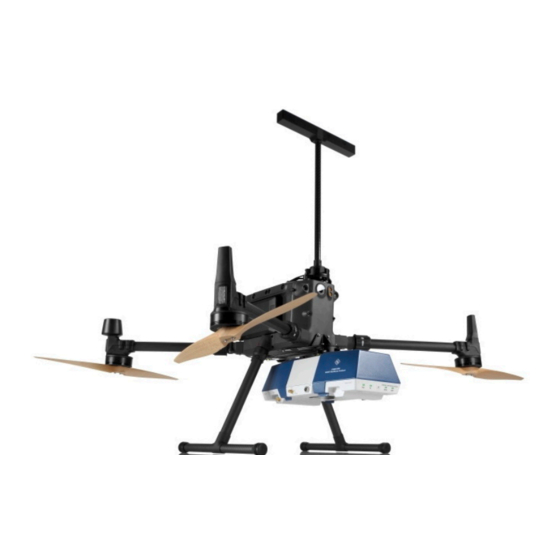
4.3.1 Mounting the R&S EVSD1000 on a drone You mount the R&S EVSD1000 on a drone via the adapter on the top panel. Cur- rently, an adapter set is available for the DJI M300 (R&S EVSD1-Z20 Drone adapter DJI M300 RTK). You can design a customized drone adapter for other drone types or to mount the R&S EVSD1000 to the drone from a different posi-... - Page 16 Figure 4-1: Example of a R&S EVSD1000 mounted to a DJI M300 drone To mount the R&S EVSD1000 to a drone 1. Screw the customized drone adapter to the top panel of the R&S EVSD1000 using secured screws. Getting Started 1179.5618.02 ─ 01...
- Page 17 Figure 4-2: R&S EVSD1000 with a sample adapter 2. Fasten the drone adapter to the drone as designed. To mount the R&S EVSD1000 to a DJI M300 drone using the adapter set An optional adapter set is available for a DJI M300 drone (R&S EVSD1-Z20 Drone adapter DJI M300 RTK).
- Page 18 Preparing for use R&S EVSD1000 Setting up the R&S EVSD1000 3. Screw the adapter to the outer quick release component. 4. Screw the drone adapter with the quick release component to the front and bottom of the drone using the provided four secured screws.
- Page 19 EVSD1000 Setting up the R&S EVSD1000 6. Press and hold the quick release button (2). 7. Insert the quick release component on the R&S EVSD1000 in the quick release counterpart on the drone. 8. Stop pressing the quick release button.
-
Page 20: Opening And Closing The Front And Rear Covers
Otherwise you can damage the antenna. Place the R&S EVSD1000 on a stable, flat and level surface. Ensure that the surface can support the weight of the R&S EVSD1000. For information on the weight, see the data sheet. - Page 21 3. Slide off the cover. To close the front and rear covers 1. Slide the cover onto the R&S EVSD1000 from the side. 2. Press the cover down onto the casing until the tabs lock into place. Getting Started 1179.5618.02 ─ 01...
-
Page 22: Connecting The Ils/Vor Antenna To The R&Sevsd1000
To connect a receiving antenna to the bottom of the R&S EVSD1000 Prerequisite: R&S EVSD1-Z3 V/UHF antenna 1. On the bottom panel of the R&S EVSD1000, unscrew the protection cover. Figure 4-3: Removing the protection cover from the bottom panel 2. - Page 23 ® Preparing for use R&S EVSD1000 Connecting the ILS/VOR antenna to the R&S EVSD1000 5. Screw the adapter + quick release component to the bottom panel of the R&S EVSD1000. 6. Unfasten the quick release clasp (1). 7. Press and hold the quick release button (2).
- Page 24 Preparing for use R&S EVSD1000 Connecting the ILS/VOR antenna to the R&S EVSD1000 10. Make sure that the two components are connected securely. 11. Fasten the quick release clasp. 12. Connect the RF output cable ("pig tail") of the receiving antenna to the provi- ded RF extension cable.
- Page 25 Preparing for use R&S EVSD1000 Connecting the ILS/VOR antenna to the R&S EVSD1000 4. Screw the adapter and quick release component to the top of the drone. 5. Unfasten the quick release clasp (1). 6. Press and hold the quick release button (2).
-
Page 26: Connecting To Lan
Windows firewall configuration, you can use the interface, for exam- ple: ● To stream measurement data from the R&S EVSD1000 to a connected device ● To access or control the measurement from a remote device using a VNC cli- ●... - Page 27 ● Changing IP addresses ● Exchanging hardware Errors can affect the entire network. 1. Connect the R&S EVSD1000 to the LAN via the LAN interface on the right panel of the instrument. 2. Start a VNC client on the connected remote device.
-
Page 28: Setting Up A Data Link (Wi-Fi) Connection
Setting up a data link (Wi-Fi) connection The R&S EVSD1000 can be equipped with an optional R&S EVSD1-Z5 Data-link- module (Wi-Fi). Thus, you can configure the R&S EVSD1000 as a Wi-Fi access point for wireless communication from a remote device. The data-link-module (Wi-Fi) is connected using the connectors in the data link slot on the rear of the R&S EVSD1000 (see... - Page 29 "Opening and closing the front and rear covers", on page 20. 2. A hook-and-loop fastener is taped to the R&S EVSD1000, in front of the data link slot. Tape the upper part of the fastener to the data-link-module (Wi-Fi) as shown in Figure 4-4.
- Page 30 The R&S EVSD1000 is configured as a Wi-Fi access point using a DHCP server. By default, the following settings are defined. 2. Usually, you can access the R&S EVSD1000 using the default IP address and Wi-Fi password without further configuration. The default IP address is 192.168.1.1.
-
Page 31: Connecting To Gnss
Connecting to GNSS A GNSS receiver provides synchronization data for time and positioning results. There are three ways to provide GNSS data to the R&S EVSD1000: ● Using the R&S EVSD1-Z6 GNSS RTK device and R&S EVSD1-Z7 GNSS antenna options ●... - Page 32 Connecting to GNSS To receive GNSS data from the DJI M300 You can connect the R&S EVSD1000 to a drone and use the drone as a source for position and time data. Thus, the R&S EVSD1000 does not require an addi- tional GNSS receiver.
- Page 33 R&S EVSD1000. For more information on the commands described here, see the R&S EVSD1000 user manual. 3. Specify the application ID on the R&S EVSD1000 by sending the remote com- mand DJI:APPID. For example: DJI:APPID 1120702 4.
-
Page 34: Connecting To Power
For details, see the R&S EVSD1000 user manual. Connecting to power The R&S EVSD1000 is equipped with a DC power supply connector that can be connected to the board power of a drone. Optionally, you can operate the R&S EVSD1000 by a battery (R&S EVSD1-Z1 Battery pack). - Page 35 "Handling batteries safely" on page 7. If the battery pack is installed and no DC power is supplied, the R&S EVSD1000 automatically switches to battery operation. The power mode and charge condi- tion of the battery are indicated by the "Power" LED on the front panel of the R&S EVSD1000 (see...
- Page 36 2 = Battery slot at front of the R&S EVSD1000 5. Charge the battery pack using the R&S EVSD1-Z2 Battery charger. 6. Insert the charged battery pack into the slot at the front of the R&S EVSD1000 with the charge state indicator LED facing upwards.
-
Page 37: Switching On Or Off
3. Plug the AC power cable into a two-pin power outlet with ground contact. The green operating LED of the AC/DC power supply connector lights up. The green Power LED on the front panel of the R&S EVSD1000 lights up. 4.10... -
Page 38: Performing An Autocalibration
The R&S EVSG1-Z11 Verification test software enables the cus- tomer to verify the R&S EVSD1000 on site. The main task of the R&S EVSG1-Z11 Verification test software is to provide navaids signals that are more accurate than the R&S EVSD1000 itself. - Page 39 The "Setup - CAL" display shows the status for each calibration step. When completed, after a few minutes, all entries must have the status "OK". For more information on autocalibration, see the R&S EVSD1000 user manual. Getting Started 1179.5618.02 ─ 01...
-
Page 40: Instrument Tour
Note that some of the connectors are behind a protective cover, see Chapter 4.4, "Opening and closing the front and rear covers", on page 20. Figure 5-1: R&S EVSD1000 - Front panel view (with semi-transparent cover) Chapter 5.1.1, "Power LED", on page 41 Chapter 5.1.2, "RX input LED",... - Page 41 Valid signal yellow Invalid signal detected No signal detected 5.1.3 Power on/off switch Switches the R&S EVSD1000 on and off. When the instrument is ready for opera- tion, the Power LED lights green. See also Chapter 4.10, "Switching on or off",...
- Page 42 ® Instrument tour R&S EVSD1000 Front panel 5.1.4 LAN/ data link LED Indicates the state of the LAN or data link connection. See Chapter 5.3.1, "LAN (ethernet)", on page 45 and Chapter 5.2.1, "Data link antenna connector", on page 43.
- Page 43 43 Chapter 5.2.2, "RX In connector", on page 44 Chapter 5.2.3, "GNSS connector", on page 44 For the specification of the following interfaces, see the R&S EVSD1000 data sheet. ● Data link antenna connector................43 ● RX In connector....................
- Page 44 The RX input connector is a 50 Ω SMA connector. Use the RX input connector to provide signal input (max. +13 dBm) from a R&S EVSD1-Z3 V/UHF antenna to the R&S EVSD1000. The antenna itself is connected to the bottom panel of the R&S EVSD1000, see Chapter 5.5, "Bottom panel", on page 48.
- Page 45 M8-D IP67 connector with 4 contacts providing a FastEthernet LAN connection. The pins are assigned according to IEC 61076-2-114. Operate the R&S EVSD1000 remotely using the LAN connection (Fast Ethernet). The LAN connection can also be used to stream measurement data (TCP port 8000;...
- Page 46 34. Rear panel The rear panel of the R&S EVSD1000 provides a data link slot with connectors. In the R&S EVSD1000 data link slot, you can connect an optional R&S EVSD1-Z5 Getting Started 1179.5618.02 ─ 01...
- Page 47 Chapter 4.4, "Opening and closing the front and rear covers", on page 20. Figure 5-4: R&S EVSD1000 - Rear panel view (with installed optional R&S EVSD1-Z5 Data- link-module (Wi-Fi)) 1 = USB-C connector 2 = SMA connectors The R&S EVSD1000 data link slot provides the following connectors: ●...
- Page 48 5.5.1 Mounting position for ILS (LOC/GS) and VOR receiver antenna You can connect the R&S EVSD1-Z3 V/UHF antenna to the R&S EVSD1000 via an adapter on the bottom panel. See also Chapter 4.5, "Connecting the ILS/VOR antenna to the R&S EVSD1000",...
- Page 49 LAN. Top panel Figure 5-6: R&S EVSD1000 - Top panel view 1 = Drone adapter The R&S EVSD1000 is equipped with a mechanical adapter on its top panel to mount it to a drone. Getting Started 1179.5618.02 ─ 01...
- Page 50 EVSD1000 Top panel Adapter sets are available for the following drone types: ● DJI M300 To mount the R&S EVSD1000 on any other type of drone, create a customized adapter (see Chapter 4.2, "Selecting and preparing the system components", on page 14).
-
Page 51: Operating Basics
EVSD1000 Basic connection settings Operating basics The R&S EVSD1000 is designed for operation on a drone, and is thus completely remote-controlled, via predefined commands. It does not have a graphical user interface for manual interaction. Nevertheless, the instrument can also be controlled manually, by simulating a user interface on a remotely connected device, and using a connected keyboard. - Page 52 Using a VNC viewer application, you simply connect to the instrument, defined by its IP address. A graphical interface for the R&S EVSD1000 is shown on the con- trol PC. The keys and other graphical user interface elements are operated using associated keyboard shortcuts on the connected keyboard.
- Page 53 Operating basics R&S EVSD1000 Manual operation from a VNC viewer Figure 6-1: R&S EVSD1000 - GUI overview 1 = Measurement settings area (numeric modes only) 2 = Measurement result area 3 = Softkeys to edit settings and activate functions 4 = Status bar...
- Page 54 ● Battery status and charge status (in %) 6.2.2 Keyboard commands for operation via a VNC viewer Table 6-1 shows the mapping between the keyboard shortcuts and the interface elements on the R&S EVSD1000. Table 6-1: Keyboard commands (VNC viewer) Keyboard Usage Preset...
- Page 55 ® Operating basics R&S EVSD1000 Manual operation from a VNC viewer Keyboard Usage Meas Config Softkey 1 Softkey 2 Softkey 3 Softkey 4 Softkey 5 Softkey 6 Softkey 7 Show additional softkeys Trigger Single CH/FREQ MTime BACKSPACE Back ENTER Enter Ampt Getting Started 1179.5618.02 ─...
- Page 56 Marker 6.2.3 Changing settings and activating functions All functions available on the R&S EVSD1000 can be accessed using the keys on the external keyboard. Some keys provide a softkey menu on the display with fur- ther functions and settings. 1. Select a key as described in...
- Page 57 ® Operating basics R&S EVSD1000 Manual operation from a VNC viewer 6.2.4 Entering data You enter data in input fields using the external keyboard, as described in Table 6-1. Entering numeric parameters If a field requires numeric input, the keypad provides only numbers.
- Page 58 ® Operating basics R&S EVSD1000 Manual operation from a VNC viewer Correcting an entry 1. Using the arrow keys, move the cursor to the right of the entry you want to delete. 2. Press the [BACK] key. The entry to the left of the cursor is deleted.
- Page 59 51. Remote control is performed using predefined remote commands which are sent from the control device to the R&S EVSD1000. The R&S EVSD1000 can also return queried data to the control device. While in remote control, the R&S EVSD1000 display indicates "Remote" in the status bar.
-
Page 60: Contacting Customer Support
® Contacting customer support R&S EVSD1000 Contacting customer support Technical support – where and when you need it For quick, expert help with any Rohde & Schwarz product, contact our customer support center. A team of highly qualified engineers provides support and works with you to find a solution to your query on any aspect of the operation, program- ming or applications of Rohde &... -
Page 61: Reference: Dimensions For Drone Adapter
EVSD1000 Reference: Dimensions for drone adapter The R&S EVSD1000 is equipped with a mechanical adapter on its top panel to mount it to a drone. To mount the R&S EVSD1000 on a customer-specific drone, create a customized adapter according to the following dimensions. - Page 62 EVSD1000 Figure 8-2: Drone dimensions for adapter (top view) Center of gravity The center of gravity of the R&S EVSD1000 lies within the area indicated by Ø25 Figure 8-2. It remains within that area even if the optional components R&S EVSD1-Z1 Battery pack or R&S EVSD1-Z5 Data-link-module (Wi-Fi) are installed.
Need help?
Do you have a question about the EVSD1000 and is the answer not in the manual?
Questions and answers