Advertisement
Quick Links
Advertisement
Chapters

Subscribe to Our Youtube Channel
Related Manuals for Rohde & Schwarz EDS300


Summary of Contents for Rohde & Schwarz EDS300
- Page 1 ® R&S EDS300 DME/PULSE Analyzer User Manual (Â2æI2) 5202882502 Version 02...
- Page 2 ® This manual applies to the following R&S EDS300 models with software version 4.20 and later: ● ® R&S EDS300 (5202.7006.02) (For exceptions see the data sheet.) In addition to the base unit, the following options are described: ● R&S®EDS-B1 Additional RX Unit (5202.7170.02) ●...
-
Page 3: Table Of Contents
Safety instructions......................7 Labels on the product....................9 Warning messages in the documentation..............10 Korea certification class A..................10 2 Documentation overview..............11 3 Welcome to the R&S EDS300..............12 4 Getting started..................13 Preparing for use......................13 Instrument tour......................20 Operating basics......................29 5 Measurement basics................35 Evaluating DME signals....................35... - Page 4 How to set up the R&S EDS300 interrogator............103 10.5 How to analyze pulses graphically................104 10.6 How to set up the R&S EDS300 for TACAN measurements........105 10.7 How to save and load measurement settings............106 11 Remote commands for DME/Pulse analysis........109 11.1...
- Page 5 ® Contents R&S EDS300 A References..................166 B DME channel frequency list.............. 167 C Format description of DME measurement data......183 List of commands................189 Index....................193 User Manual 5202.8825.02 ─ 02...
- Page 6 ® Contents R&S EDS300 User Manual 5202.8825.02 ─ 02...
-
Page 7: Safety And Regulatory Information
Target audience This document is aimed at installers, technicians and operators of the R&S EDS300. It assumes the readers are familiar with basic handling of electrical equipment and have knowledge of avionic navigation systems. - Page 8 ® Safety and regulatory information R&S EDS300 Safety instructions aged or broken, stop using the product. Contact Rohde & Schwarz customer service at https://www.rohde-schwarz.com/support. Operating the product The product is intended for mobile use. The maximum weight of the product is provi- ded in the data sheet.
-
Page 9: Labels On The Product
® Safety and regulatory information R&S EDS300 Labels on the product ● Do not expose the battery to high temperatures such as open flames, hot surfaces and sunlight. ● Only use the battery with the designated Rohde & Schwarz product. -
Page 10: Warning Messages In The Documentation
® Safety and regulatory information R&S EDS300 Korea certification class A Table 1-1: Labels regarding product and environment safety Labeling in line with EN 50419 for disposal of electrical and electronic equipment after the prod- uct has come to the end of its service life. -
Page 11: Documentation Overview
Further documents are available at: www.rohde-schwarz.com/product/EDS300. Getting Started manual Introduces the R&S EDS300 and describes how to set up and start working with the product. Includes basic operations, typical measurement examples, and general infor- mation, e.g. safety instructions, etc. A printed version is delivered with the instrument. -
Page 12: Welcome To The R&S Eds300
(R&S EDS-K1 option) and performs in-depth pulse analysis (R&S EDS-K2 option). The modular design of the R&S EDS300 provides a high degree of flexibility to adapt it to the task at hand. An interrogator (R&S EDS-B2 option) with adjustable output power (-80 dBm to +30 dBm peak power) is available for RX measurements. -
Page 13: Getting Started
® Getting started R&S EDS300 Preparing for use 4 Getting started ● Preparing for use.....................13 ● Instrument tour......................20 ● Operating basics..................... 29 4.1 Preparing for use Here, you can find basic information about setting up the product for the first time. - Page 14 7 4.1.4.1 Placing the product on a bench top If you want to set up the R&S EDS300 on a benchtop or prepare the R&S EDS300 for mobile use, proceed as follows. To place the product on a bench top 1.
- Page 15 2. Lift the R&S EDS300 to shelf height. 3. Grab the handle and push the R&S EDS300 onto the shelf until the rack brackets fit closely to the rack. 4. Tighten all screws in the rack brackets with a tightening torque of 1.2 Nm to secure the R&S EDS300 in the rack.
- Page 16 1. Loosen the screws at the rack brackets. 2. Remove the R&S EDS300 from the rack. 3. If placing the R&S EDS300 on a bench top again, unmount the adapter kit from the R&S EDS300. Follow the instructions provided with the adapter kit.
- Page 17 Chapter 4.2.1, "Front panel view", on page 20). If the interrogator option R&S EDS-B2 is installed on the R&S EDS300, the instrument can also provide HF output to a transmitter antenna via the "RF1 IN/OUT" connector (see also "Antenna connections RF1 IN/OUT and RF2 IN"...
- Page 18 The TACAN (Tactical Air Navigation) option R&S EDS-K1 is implemented as a USB stick. The TACAN stick is linked to the R&S EDS300 unambiguously via the instru- ment's MAC address. The R&S EDS300 can evaluate TACAN signals only if the TACAN stick with the TACAN software is inserted in one of the USB ports.
- Page 19 R&S EDS300 Preparing for use The TACAN stick must be inserted before the R&S EDS300 is switched on. Do not remove the stick before switching off the R&S EDS300, or else the application is closed. When the R&S EDS300 firmware is started, the TACAN functionality is copied from the stick to the RAM.
-
Page 20: Instrument Tour
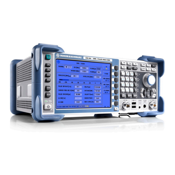
Disconnect the product from the power source. 4.2 Instrument tour 4.2.1 Front panel view This chapter describes the front panel of the R&S EDS300, including all function keys and connectors. Figure 4-1: Front panel view of the R&S EDS300 Power key... - Page 21 [VOL] Volume control for audio output [SAVE] for future use [MEM] [LOCAL] Switches between remote and local operation of the R&S EDS300 [SETUP] Provides basic instrument configuration functions, e.g.: ● Reference frequency (external/internal), noise source ● Date, time, display configuration ●...
- Page 22 N-socket, 50Ω RF output with interrogator options If the R&S EDS300 is equipped with the interrogator option R&S EDS-B2, the "RF1 IN/ OUT" connector can provide HF output to a transmitter antenna. The antenna has an equivalent frequency range and (peak) power range (1 W).
- Page 23 97. Voltage supply for external consumers: 12 VDC OUT The R&S EDS300 provides a power supply for connected external devices at the 3- pole circular "12 VDC OUT" connector. The output for external consumers such as an active receiving antenna is supplied permanently with 12 VDC / 300 mA.
- Page 24 ® Getting started R&S EDS300 Instrument tour General function keys Function Creates a screenshot of the current display For future use 4.2.1.6 Measurement keys Measurement keys provide access to the most common measurement settings and functions. A detailed description of the corresponding functions is provided in Chapter 7, "Config-...
- Page 25 In dialog boxes that contain a "Cancel" button that it activates that button. 4.2.2 Rear panel view This figure shows the rear panel view of the R&S EDS300. The individual elements are described in more detail in the subsequent sections.
- Page 26 16. 4.2.2.2 SUPPRESS IN / OUT connector The R&S EDS300 allows for a suppressor line signal to be input or output via the BNC "SUPPRESS IN / OUT" connector (see Chapter 4.1.8.2, "Connecting a suppressor line", on page 18).
- Page 27 4.2.2.6 REF 10 MHz IN/OUT The "REF 10 MHz IN/OUT" connector can provide an external reference signal to the R&S EDS300, or from the R&S EDS300 to a connected device. In either case, the ref- User Manual 5202.8825.02 ─ 02...
- Page 28 4.2.2.7 LAN interface Use the "LAN" interface to connect the R&S EDS300 to a local network for remote con- trol, printouts or data transfer. The data can be transferred with a rate of up to 1 Gbit per second. Configure the IP address and subnet mask in the general instrument set- tings.
-
Page 29: Operating Basics
The instrument name is required to establish a connection to the instrument in a LAN. 4.3 Operating basics This chapter provides an overview on how to work with the R&S EDS300. It describes what kind of information is displayed on the screen and how to operate the R&S EDS300 via the front panel keys and other interaction methods. - Page 30 "2/2" (or "1/3", "2/3", "3/3", respectively) beneath the softkeys in the display. To switch between the menus of softkey functions, press the "More softkeys" key beneath the softkeys on the front panel of the R&S EDS300. Measurement settings and results area During a measurement, the available settings are displayed at the top of the screen;...
- Page 31 Error and status messages). 4.3.2 Accessing the functionality All functions available on the R&S EDS300 can be accessed using the keys on the front panel of the instrument. Some keys provide a softkey menu on the display with further functions and settings.
- Page 32 If a field requires alphanumeric input, you can use the keypad on the front panel of the R&S EDS300. Every alphanumeric key represents several characters and one number. The decimal point key (.) represents special characters, and the sign key (-) toggles between capital and small letters.
- Page 33 ® Getting started R&S EDS300 Operating basics 5. To change from capital to small letters and vice versa, press the sign key (-). 6. When you have chosen the desired value, wait for 2 seconds (to use the same key again), or start the next entry by pressing another key.
- Page 34 In this case, check the error log for missed errors. The [UNCAL] display is only removed when the R&S EDS300 is switched off. All error and status messages displayed on the R&S EDS300 are also stored to an error log on the instrument for later inspection. (See Chapter 9.3.1, "Error...
-
Page 35: Measurement Basics
If the reply efficiency rises above the specified threshold, the R&S EDS300 immediately returns to the "track" mode. But after a specified time (by default: 10 s) the track is considered to be lost and the R&S EDS300 returns to the "search" mode to start over. -
Page 36: Reply Efficiency
R&S EDS300 RF attenuator value is decreased, the R&S EDS300 moves to the "track" mode more quickly, but also returns to the "memory" mode more quickly. 5.2 Reply efficiency The reply efficiency of a DME system is the ratio of the number of received reply pul- ses to the number of transmitted interrogation pulses. - Page 37 ® Measurement basics R&S EDS300 RF attenuator Figure 5-1: Signal paths for different attenuation modes Select the attenuator mode such that the input level always remains within the speci- fied range. For details, see "Antenna connections RF1 IN/OUT and RF2 IN"...
-
Page 38: Measurements And Results
If the appropriate hardware option (Low-Power Interrogator, R&S EDS300-B2) is instal- led, the R&S EDS300 can act as a DME interrogator. It sends out pulses to the ground station which returns the signals to the R&S EDS300 at a different frequency with a delay (see Chapter 5.1, "Evaluating DME... - Page 39 DME and TACAN measurement mode Receiver modes The R&S EDS300 can measure either the pulses sent by the interrogator to the ground station, or the reply pulses sent from the ground station to the interrogator. You specify which signals you want to measure and analyze in the measurement settings.
- Page 40 Interrogator pulse code (distance of the double pulses), according to the ICAO frequency list. 6.1.2 DME measurement results Access: [DME] Distance measurements are performed in a specific mode on the R&S EDS300, the "DME" mode. The following results are displayed for a distance measurement. Graphical results are described in Chapter 7.3, "Performing pulse...
- Page 41 For reference measurements requiring very high accuracy, you can connect a power sensor from the R&S NRP family to the R&S EDS300 USB port. Results delivered by the power sensor are displayed on the R&S EDS300 without further configuration. See "NRP AVRG/NRP PEAK"...
- Page 42 ID Period [s] Time between two measured ID sequences BEARING [°] TACAN signals only (requires option R&S EDS300-K1): Direction of the ground station in relation to the R&S EDS300. Remote command: on page 157 <RX>:TACAN:BEARING? User Manual 5202.8825.02 ─ 02...
- Page 43 ® Measurements and results R&S EDS300 DME and TACAN measurement mode DELAY [µs] Reply delay time, that is: the delay time between the interrogator and reply pulse, including the ground station delay (50 µs for X channels / 56 µs for Y channels).
- Page 44 ● The absolute phase of the 135 Hz signal to the auxiliary reference burst (ARB) The R&S EDS300 can evaluate TACAN signals only if the TACAN stick with the TACAN software is inserted in one of the USB ports (see Chapter 4.1.9, "Activating the...
- Page 45 ® Measurements and results R&S EDS300 DME and TACAN measurement mode Figure 6-2: TACAN measurement results (page 2) MOD.DEPTH 15Hz [%]....................45 MOD.DEPTH 135Hz [%]....................45 BEARING [°]........................46 PHASE SHIFT [°]......................46 FREQ 15Hz [Hz]......................46 FREQ 135Hz [Hz]......................46 PHASE 15Hz [°]......................
- Page 46 DME and TACAN measurement mode Remote command: on page 158 <RX>:TACAN:MOD_DEPTH_135HZ? BEARING [°] Direction of the ground station in relation to the R&S EDS300. Remote command: on page 157 <RX>:TACAN:BEARING? PHASE SHIFT [°] Measured phase shift between the 15 Hz and 135 Hz components...
-
Page 47: Multi-Dme Measurements
Multi-DME measurements are a special method of performing distance measurements for 10 ground stations at the same time. The optional R&S EDS300-K5 (Multi-DME) software is only usable in connection with the R&S EDS300-B2 or R&S EDS300-B4 (low- or high-power interrogator) hardware options and a second RX module option R&S EDS300-B1. -
Page 48: Graphical Pulse Analysis
® Measurements and results R&S EDS300 Graphical pulse analysis The following settings and results are displayed for a Multi-DME measurement. Display Description Remote command SLOT Slots 1 … 10 The slot selected for entry is indicated by a green frame. - Page 49 EDS300 Graphical pulse analysis R&S EDS300 pulse analysis is used to test the RF output signal of DME / TACAN ground stations and interrogators and analyze pulse characteristics graphically. In "Pulse" mode, the power levels at a specific interrogator or transponder channel fre- quency are measured.
- Page 50 ® Measurements and results R&S EDS300 Graphical pulse analysis "Pulse" view. Which analysis function is currently selected is displayed in the results area and on the "Analysis" softkey. Markers To determine the individual pulse parameters, the markers must be set to different points in the pulse traces.
- Page 51 ® Measurements and results R&S EDS300 Graphical pulse analysis Figure 6-4: Pulse rise time results in Pulse view Remote command: on page 161 <RX>:PULSEVIEW:ANALYSIS? Pulse duration Pulse duration for each pulse in µs, calculated as the difference between two markers (M2-M1).
- Page 52 ® Measurements and results R&S EDS300 Graphical pulse analysis Figure 6-5: Pulse duration results in Pulse view Remote command: on page 161 <RX>:PULSEVIEW:ANALYSIS? Pulse decay time Pulse decay time for each pulse in µs, calculated as the difference between two mark- ers (M2-M1).
- Page 53 ® Measurements and results R&S EDS300 Graphical pulse analysis Figure 6-6: Pulse decay time results in Pulse view Remote command: on page 161 <RX>:PULSEVIEW:ANALYSIS? Pulse spacing Pulse spacing between the pulses of a pulse pair in µs, calculated as the difference between two markers (M2-M1).
- Page 54 ® Measurements and results R&S EDS300 Graphical pulse analysis Figure 6-7: Pulse spacing results in Pulse view Remote command: on page 161 <RX>:PULSEVIEW:ANALYSIS? Peak variation Variation in pulse peak power values between two pulses, in dB. Remote command: on page 161 <RX>:PULSEVIEW:ANALYSIS?
- Page 55 ® Measurements and results R&S EDS300 Graphical pulse analysis Mrk. max to peak 1 The difference between two markers (M2-M1). Marker 1 is set to the peak power level of the first pulse, marker 2 is set to the peak power level of the second pulse.
-
Page 56: Configuring And Performing Measurements
7.1 Configuring signal input and output Access: [SETUP] The R&S EDS300 can analyze signals received by its RF IN interface, but also provide output to the same interface. Furthermore, a reference signal can be provided as input to the R&S EDS300 to improve accuracy of the measurements. All settings concerning signal input and output are described here. - Page 57 "RF 1 IN" RF input from the "RF 1 IN/OUT" connector on the front panel of the R&S EDS300 "RF 2 IN" RF input from the "RF 2 IN" connector on the front panel of the R&S EDS300...
- Page 58 120 SETUP:RF1_EXTATTENUATION on page 120 SETUP:RF2_EXTATTENUATION 7.1.2 Configuring signal output Access: [SETUP] > "Signal Out" Different signals can be provided at one of the R&S EDS300's output connectors. Trigger Out Mode......................59 Analog Out........................59 User Manual 5202.8825.02 ─ 02...
- Page 59 For each decoded ARB (auxiliary reference burst), a square pulse with a 1 μs pulse width is output. Only available for TACAN analysis (requires option R&S EDS300- K1). "MDME SLOT" Each time the channel is switched, a square pulse with a 1 μs pulse width is output.
- Page 60 Defines whether the [REF 10 MHz IN/OUT] connector on the rear panel of the R&S EDS300 is used to receive a reference frequency from an external device, or to provide the internal reference frequency of the R&S EDS300 as output to a connected device.
- Page 61 7.1.4 Configuring DME interrogator signals Access: [SETUP] > "DME Interrog" The R&S EDS300 can act as a DME interrogator, sending out pulses to the ground station which returns the signals to the R&S EDS300 at a different frequency with a delay (see Chapter 5.1, "Evaluating DME...
- Page 62 ® Configuring and performing measurements R&S EDS300 Configuring signal input and output Min. Reply Effic. (Tracking)................... 62 Delay Offset........................63 TX Pulse Shape......................63 ICAO Override.......................63 Type of Prediction Defines the type of algorithm used to calculate the expected reply pulse.
- Page 63 "DME" Asymmetric Gauss pulse with a rise time of 2.0 μs and a fall time of "TAC" 2.7 μs Only available for TACAN measurements, requires option R&S EDS300-K1. Remote command: on page 133 <RX>:DST:PULSE_SHAPE ICAO Override Ignores the ICAO specifications regarding the maximum pulse repetition rate.
- Page 64 "GPS" window. Figure 7-1: GPS view with GPS data The following GPS data for the current position of the R&S EDS300 is displayed in the "GPS" window: Table 7-1: GPS data in the GPS window...
-
Page 65: Configuring Dme Measurements
GPRMC The GPRMC (Global Positioning Recommended Minimum Specific = minimum information) dataset received by the R&S EDS300 is displayed as an ASCII character set with 4800 Bd. GPGGA GPGGA (Global Positioning System Fix Dat) dataset containing the most important informa- tion of the GPS position and accuracy. -
Page 66: Changing The Receiver (Rx) Channel Number
® Configuring and performing measurements R&S EDS300 Configuring DME measurements Changing the receiver (RX) channel number..............66 Channel selection X, Y....................67 Changing the receiver (RX) frequency................67 RX Pulse Code (P.Code)....................67 VHF Frequency (VHFF)....................67 Interrogator Transmission (TX) frequency..............68 TX Pulse Code (P.Code).................... -
Page 67: Channel Selection X, Y
RX frequency, but also by the corresponding VHF fre- quency. If you enter a valid VHF frequency in the "RX freq" field, the R&S EDS300 rec- ognizes it. The entered frequency is then displayed as the "VHF Frequency (VHFF)"... -
Page 68: Interrogator Transmission (Tx) Frequency
PRR for Track Mode. An active transmitter is indicated by a yellow "TX ON" message in the status bar of the R&S EDS300 screen. NOTICE! Risk of damage to the instrument or injury due to false transmission settings. Only change transmission settings while the transmitter is deactivated. Falsely entered settings can lead to unexpected output levels that can cause damage or injury. -
Page 69: Receiver (Rx) Mode
Remote command: on page 125 <RX>:DME:ATTMODE Receiver (RX) Mode Defines the signal to be received and analyzed by the R&S EDS300, depending on the measurement task. The currently selected mode is indicated on the softkey. "Reply" (Default) The signal transmitted by the DME ground station is mea- sured. -
Page 70: Performing Pulse Analysis
<RX>:DME:DEMOD_BW 7.3 Performing pulse analysis R&S EDS300 pulse analysis is used to test the RF output signal of DME / TACAN ground stations and interrogators and analyze pulse characteristics graphically. In Pulse mode, the power levels at a specific interrogator or transponder channel fre- quency are measured. - Page 71 ® Configuring and performing measurements R&S EDS300 Performing pulse analysis played in a power vs time diagram, similarly to an oscilloscope. Additionally, character- istic pulse parameters are determined using markers in the diagram. You can change the channel and frequency to be measured directly in the Pulse view, "Changing the receiver (RX) channel number"...
- Page 72 ® Configuring and performing measurements R&S EDS300 Performing pulse analysis X-axis Scaling (Time/Div) Time per division; defines the scaling of the x-axis, which consists of 10 divisions. The valid value range is from 0.5 μs to 50 μs. Note that the hardware supports a minimum of 2 μs/div. Lower values do not reduce the time between two captured points, but represent a zoomed display.
- Page 73 "Maxhold" The maximum value is determined over all previously measured pul- ses (pairs) and displayed. The R&S EDS300 saves each trace point in the trace memory only if the new value is greater than the previous one.
- Page 74 RX frequency, but also by the corresponding VHF fre- quency. If you enter a valid VHF frequency in the "RX freq" field, the R&S EDS300 rec- ognizes it. The entered frequency is then displayed as the "VHF Frequency (VHFF)"...
- Page 75 ® Configuring and performing measurements R&S EDS300 Performing pulse analysis If the frequency is inside the valid range, but not assigned to a channel according to the ICAO frequency list, and it is not a VHF frequency, the associated parameters are indicated in yellow.
- Page 76 Defines the signal which triggers the measurement. "Level" The measured input signal "External" An external trigger signal provided by a device connected to the [trigger in] connector on the rear panel of the R&S EDS300; The defined trigger level is irrelevant. "Interrog"...
- Page 77 Access: [Marker] In the graphical pulse analysis display, up to three markers can be enabled to indicate special points of interest in the diagram. The R&S EDS300 can then use these specific marker values to analyze characteristic pulse parameters. As described in Chapter 6.3, "Graphical pulse...
- Page 78 ® Configuring and performing measurements R&S EDS300 Performing pulse analysis Peak marker (Mrk. Max) Allows you to place the peak marker to any position in the measured signal manually. Enter the time which defines the x-axis value of the marker, or move the marker using the rotary knob.
-
Page 79: Data Management
Possibly you would like to restore or repeat a measurement you performed under spe- cific conditions on the R&S EDS300. Or you would like to troubleshoot a measurement and require a defined instrument state to detect the precise cause of the error. In these cases, you can store and recall instrument and measurement settings. - Page 80 Rename.........................81 Factory Preset When delivered, the R&S EDS300 has a default configuration. You can restore this defined initial state at any time as a known starting point for measurements. Presetting is often recommendable as a first step in troubleshooting when unusual measurement results arise.
-
Page 81: Logging Measurement Data
[START] If a USB storage device is connected to the R&S EDS300, a data file is created on the USB device. All measurement results from the running measurement are stored in the file. The message USB LOGGING ON is displayed in the status bar. -
Page 82: Creating And Storing Screenshots
8.3 Creating and storing screenshots Access: [Setup] > "More Softkeys" > "Memory & Screenshots" You can create a screenshot of the current display on the R&S EDS300 at any time during operation. Screenshots are useful to document measurement results, for exam- ple. -
Page 83: Color Vs. Black And White Screenshot
EDS300 Creating and storing screenshots If a USB device is connected to the R&S EDS300 when the screenshot is created, the screenshot is stored there directly as a .PNG file. A dialog box with the default file name is displayed. To change the name of the file on the USB device, click in the name field and overwrite the default name. -
Page 84: Obtaining Information On Open-Source Resources
Deleting all screenshots stored on the R&S EDS300 All screenshots stored on the R&S EDS300 are deleted irrevocably. Once the screenshots have been stored to an external memory device, you can delete them from the instrument. Otherwise, you copy them again each time you create new screenshots and want to store them to a USB device. -
Page 85: General Instrument Setup
® General instrument setup R&S EDS300 General settings 9 General instrument setup Access: [SETUP] Some basic instrument settings can be configured independently of the selected mea- surement mode. Usually, you configure most of these settings initially when you set up the instrument according to your personal preferences or requirements. -
Page 86: Setting Up A Network (Lan) Connection
117 SETUP:COUNT_PULSES 9.2 Setting up a network (LAN) connection The R&S EDS300 is equipped with a network interface and can be connected to an Ethernet LAN (local area network). The interface can be used, for example: ● To transfer data between a controlling device and the test device, e.g. to run a remote control program. - Page 87 How to configure the network (LAN) connection.............89 ● How to set up a remote connection.................89 9.2.1 Network settings Access: [Setup] > "Network" To operate the R&S EDS300 in a network, the following settings must be configured. User Manual 5202.8825.02 ─ 02...
- Page 88 ® General instrument setup R&S EDS300 Setting up a network (LAN) connection TCP/IP DHCP....................... 88 TCP/IP Address......................88 TCP/IP Netmask......................88 TCP/IP Gateway......................89 Hostname........................89 TCP/IP DHCP If the network supports dynamic TCP/IP configuration using the Dynamic Host Configu- ration Protocol (DHCP), all address information can be assigned automatically. In this case, the TCP/IP parameters are not editable.
- Page 89 See also "IP address vs host name" on page 87. 9.2.2 How to configure the network (LAN) connection To use the R&S EDS300 in a network, connect the instrument to the network by its LAN connector (see Chapter 4.2.2.7, "LAN interface", on page 28).
-
Page 90: Obtaining System Information
Access: [Setup] > "Error Log" The last 100 instrument status messages or errors displayed in the status bar during operation of the R&S EDS300 are also stored in an error log file on the instrument (see also Chapter 4.3.4, "Error and status messages",... - Page 91 If you detect that the latest software version is not yet installed, simply insert a USB storage device with the latest version in the R&S EDS300 and press the [ENTER] key. If a software installation file is found on the USB device, a software update is automati- cally started (after confirmation).
- Page 92 Access: [Setup] > "More Softkeys" > "Hardware Status 1" The hardware status overview provides information on the current operating status of the individual hardware components in the R&S EDS300, such as test voltages and temperatures. User Manual 5202.8825.02 ─ 02...
- Page 93 The "Overall Status" in the hardware status overview is indicated as "NOK" (not OK). As soon as the test voltage returns to the allowed range, the "Overall Status" returns to "OK". The "UNCAL" display, however, remains until the R&S EDS300 is switched off. Test voltages are color-coded: Table 9-1: Test voltage color-coding...
- Page 94 ® General instrument setup R&S EDS300 Obtaining system information Figure 9-2: Hardware status for the mainboard, the power supply and the antenna distributing unit (DU board) - page 1 The second overview ("Hardware Status 2") provides information on the integrated receiver modules.
-
Page 95: Updating The Software
9.4 Updating the software Access: [Setup] > "More Softkeys" > "Inventory" Software updates and the Release Notes describing the improvements and modifica- tions for the R&S EDS300 are provided on the Internet at: http://www.rohde-schwarz.com/firmware/eds300 To update the software version 1. Store the software version to a USB storage device. -
Page 96: Activating Additional Options
To activate the license key 1. Press the [Setup] key. Press the "More softkeys" key. 3. Press the "Options" softkey to display an overview of all available R&S EDS300 options. 4. Press the [Enter] button to open an input edit field for "Key". -
Page 97: Configuring The Display And Audio Output
If the key is valid, the purchased options are enabled and identified as "available" in the overview. Figure 9-4: Available R&S EDS300 options If the key is not valid, the entered number is displayed in red. Figure 9-5: Invalid option key Correct the number and try again. - Page 98 Remote command: on page 116 SETUP:AF_VOLUME Speaker Enables or disables AF output at the loudspeaker on the rear panel of the R&S EDS300. Remote command: on page 119 SETUP:ANALOG_OUT_MODE Display Update Rate Defines the rate at which the display is updated to show new measurement results.
- Page 99 A running measurement and data logging continues as usual. To switch the light back on, press any key or turn the rotary knob on the R&S EDS300. Note: Do not press the [Power On/Off] switch. Turning off the instrument results in a data loss if a measurement was running.
- Page 100 To change the volume setting for the loudspeaker quickly during regular operation of the R&S EDS300, press the [VOL] key on the front panel. The volume setting is tempo- rarily displayed as a bar graph in the status bar of the display. Turn the rotary knob to change the volume and confirm the setting by pressing the [ENTER] key or the rotary knob.
-
Page 101: How To Perform Measurements And Analyze Pulses With The R&S Eds300
How to save and load measurement settings............106 10.1 How to configure signal input and output The R&S EDS300 can analyze signals received by its "RF IN" interface. It can also provide output to other interfaces. To configure the input signal for analysis 1. -
Page 102: How To Perform A Distance Measurement
If an external reference source is found, "Ext.Reference: Present" is indicated. 5. Confirm the setting by pressing the [ENTER] key or the rotary knob. The R&S EDS300 uses the external frequency from the connected device as a ref- erence. To provide the internal reference frequency on the R&S EDS300 as output 1. -
Page 103: How To Analyze Interrogator Pulses
103. 10.4 How to set up the R&S EDS300 interrogator The following step-by-step instructions demonstrate how to set up the R&S EDS300 to send interrogator pulses and evaluate them. 1. Select [Setup]. 2. Select "More softkeys", then "DME Interrog.". -
Page 104: How To Analyze Pulses Graphically
10. If necessary, select "TX P. Width" or "TX Level" (in the second softkey menu) to change the interrogator pulse width or the pulse power level, respectively. The R&S EDS300 now acts and behaves like the on-board interrogator of a normal plane, sending interrogator pulses at the defined pulse rate. -
Page 105: How To Set Up The R&S Eds300 For Tacan Measurements
The power level for the marker is displayed above the diagram ("Mark1"). 10.6 How to set up the R&S EDS300 for TACAN measure- ments The following step-by-step instructions demonstrate how to set up the R&S EDS300 to measure and analyze pulses from TACAN signals. 1. Switch off the R&S EDS300. -
Page 106: How To Save And Load Measurement Settings
Default factory settings can also be restored to the instrument at any time. To restore factory default settings 1. Press the [Preset] key on the front panel of the R&S EDS300. 2. Select the "Factory Preset" softkey. 3. Confirm the message. - Page 107 How to save and load measurement settings To recall stored measurement settings 1. Press the [Preset] key on the front panel of the R&S EDS300. 2. Select the "Select" softkey. The number of the currently selected User Preset is indicated on the softkey. By default, the User Preset number 1 is selected.
- Page 108 ® How to perform measurements and analyze pulses with the R&S EDS300 R&S EDS300 How to save and load measurement settings The number of the currently selected User Preset is indicated on the softkey. By default, the User Preset number 1 is selected.
-
Page 109: Remote Commands For Dme/Pulse Analysis
11 Remote commands for DME/Pulse analysis The following commands are required to perform DME/ pulse analysis with the R&S EDS300 in a remote environment. It is assumed that the R&S EDS300 has already been set up for remote operation in a network as described in Chapter 9.2,... -
Page 110: Configuring Remote Operation
EDS300 Configuring remote operation 11.1 Configuring remote operation The R&S EDS300 can be operated in the following modes: ● Local mode: manual operation using the graphical user interface directly at the instrument is available; remote commands can also be executed ●... - Page 111 Usage: Setting only Manual operation: "Creating a screenshot" on page 82 LOCAL Switches back to local operation of the R&S EDS300. The graphical user interface of the R&S EDS300 becomes available again. Return values: <SettingResult> READY Setting was successfully applied.
-
Page 112: Obtaining Instrument Information
<State> ON | OFF Remote lock is set; no local operation by keyboard is possible. The "LOCAL" button on the R&S EDS300 has no effect. To enable local operation again, release the remote lock (using REMOTELOCK OFF. Releases the remote lock; local operation is enabled again. - Page 113 This command clears the error log. Return values: <State> READY. The command was executed successfully. GETERRORLOG This command retrieves error log entries. Return values: <Error-Log> GETHWINVENTORY Queries the hardware modules installed in the R&S EDS300. Return values: <HWModules> string Example: GETHWINVENTORY //Result: //EDS300K:5202.7006K02,999999,01.00 //EDST300:5202.7006.02,101325,02.00 //MAINBOARD:5202.7035.02,999999,06.00 //EDS_DU:5202.7058.02,101343,05.00...
- Page 114 ® Remote commands for DME/Pulse analysis R&S EDS300 Obtaining instrument information GETHWSTATUS Queries the status of the hardware modules inside the R&S EDS300. Return values: <HWStatus> OK | NOK An error has occurred for at least one hardware element. Example:...
- Page 115 ® Remote commands for DME/Pulse analysis R&S EDS300 Obtaining instrument information Return values: <Version> string Usage: Query only MAIN_BOARD_CPLD_VER? Queries the main board CPLD-Software version Return values: <Version> string Usage: Query only MAIN_BOARD_FPGA_VER? Queries the main board FPGA-Software version Return values: <Version>...
-
Page 116: General Instrument Setup
® Remote commands for DME/Pulse analysis R&S EDS300 General instrument setup 11.3 General instrument setup ..........................116 *RST .......................116 FACTORY_PRESET ....................116 SETUP:AF_VOLUME? ..................... 116 SETUP:AF_VOLUME ..................... 117 SETUP:COUNT_PULSES? ....................117 SETUP:COUNT_PULSES ..................117 SETUP:DISPLAY_UPDATE_MS? ..................117 SETUP:DISPLAY_UPDATE_MS ....................117 SETUP:MORSEMOST ......................117 SETUP:SPEAKER? ......................117... - Page 117 Remote commands for DME/Pulse analysis R&S EDS300 General instrument setup SETUP:COUNT_PULSES? SETUP:COUNT_PULSES <PulseType> Determines whether the R&S EDS300 counts single or double pulses (pulse pairs) in the measured signal. Parameters: <PulseType> DOUBLE Only double pulses are counted, that is: two identical pulses sent with the required pulse spacing.
-
Page 118: Configuring Signal Input And Output
® Remote commands for DME/Pulse analysis R&S EDS300 Configuring signal input and output Parameters: SwitchSpek ON | OFF Return values: <SettingResult> READY Setting was successfully applied. ERROR An error occurred; setting was not successful. 11.4 Configuring signal input and output ...................... -
Page 119: Getgpssync
"Sync" on page 65 SETUP:ANALOG_OUT_MODE? SETUP:ANALOG_OUT_MODE <Output> Queries or defines the type of analog signal to be provided at the [ANALOG OUTPUT] connector on the rear panel of the R&S EDS300. Parameters: <Output> RX_DEMOD The demodulated baseband signal is output. -
Page 120: Setup:ext_Attenuation_Type? Setup:ext_Attenuation_Type
R&S EDS300 INPUT_RF2 RF input from the "RF 2 IN" connector on the front panel of the R&S EDS300 INPUT_BBAND Analog input from the [ANALOG IN] connector on the rear panel of the R&S EDS300 *RST: INPUT_RF1 Return values: <SettingResult> READY Setting was successfully applied. -
Page 121: Setup:reference:extreference
R&S EDS300. The internal 10 MHz reference signal is used for measurement with the R&S EDS300. Output The internal 10 MHz reference signal of the R&S EDS300 is pro- vided as output to a device at the [REF 10 MHz IN/OUT] con- nector (for SETUP:REFERENCE:SOURCE INTERN). -
Page 122: Setup:trigger_Out_Mode
60 SETUP:TRIGGER_OUT_MODE? SETUP:TRIGGER_OUT_MODE <OutputTrig> Queries or defines the type of trigger signal to be provided at the [TRIGGER OUTPUT] connector on the rear panel of the R&S EDS300. Parameters: <OutputTrig> PULSE_TRIGGER For each measured DME pulse, a square pulse with the same pulse width is output synchronously. -
Page 123: Configuring Measurements
® Remote commands for DME/Pulse analysis R&S EDS300 Configuring measurements 11.5 Configuring measurements ● Configuring the measurement mode..............123 ● measurements..................... 124 ● interrogator....................131 ● Pulse analysis....................... 136 ● Multi-DME measurements..................148 11.5.1 Configuring the measurement mode ...................... 123 <RX>:MEASMODE? ....................123 <RX>:MEASMODE_DME... - Page 124 ® Remote commands for DME/Pulse analysis R&S EDS300 Configuring measurements For details see Chapter 6.2, "Multi-DME measurements", on page 47. Return values: <SettingResult> READY Setting was successfully applied. ERROR An error occurred; setting was not successful. Usage: Setting only <RX>:MEASMODE_PULSE Switches to pulse analysis mode (see Chapter 6.3, "Graphical pulse...
-
Page 125: Rx>:Dme:attmode
® Remote commands for DME/Pulse analysis R&S EDS300 Configuring measurements <RX>:DME:ATTMODE? <RX>:DME:ATTMODE <Mode> This command defines the attenuation mode. The query returns the mode that was actually used for the current measurement. The attenuation mode defines the sensitivity of the receiver board by selecting a differ-... -
Page 126: Rx>:Dme:meastime
® Remote commands for DME/Pulse analysis R&S EDS300 Configuring measurements Parameters: <RXFreq> numeric value Range: 960 MHz to 1215 MHz *RST: 962.0 MHz Default unit: MHz Return values: <SettingResult> READY Setting was successfully applied. ERROR An error occurred; setting was not successful. - Page 127 ® Remote commands for DME/Pulse analysis R&S EDS300 Configuring measurements WIDE Wide filter for wider pulses; entire pulse is measured without dis- tortions. Adjacent pulses or signal effects outside the pulse are possibly included. Return values: <SettingResult> READY Setting was successfully applied.
-
Page 128: Rx>:Dme:rxmode
Manual operation: "RF bandwidth (RF BW)" on page 70 <RX>:DME:RXMODE? <RX>:DME:RXMODE <SignalType> Queries or defines the signal to be received and analyzed by the R&S EDS300, depending on the measurement task. Parameters: <SignalType> REPLY The signal transmitted by the DME ground station is measured. -
Page 129: Setrx
® Remote commands for DME/Pulse analysis R&S EDS300 Configuring measurements Usage: Query only SETRX <BoardNo> Activates a receiver board for measurement (useful only if optional second receiver board is installed). Only one board at a time can be active. Parameters: <BoardNo>... - Page 130 Usage: Setting only Manual operation: "TX Pulse Code (P.Code)" on page 68 <RX>:DST:TXPULSE_WIDTH? <RX>:DST:TXPULSE_WIDTH <PWidth> Defines or queries the width of the pulses the R&S EDS300 interrogator transmits to the ground station. Parameters: <PWidth> numeric value Width in μs Range: 0.8 to 4.5...
-
Page 131: Rx>:Dst:delay_Offset
® Remote commands for DME/Pulse analysis R&S EDS300 Configuring measurements 11.5.3 DME interrogator ..................131 <RX>:DST:DELAY_OFFSET? ................... 131 <RX>:DST:DELAY_OFFSET ....................131 <RX>:DST:MEM_TIME? ....................131 <RX>:DST:MEM_TIME ..................132 <RX>:DST:MIN_REPLY_EFF? ..................132 <RX>:DST:MIN_REPLY_EFF ....................132 <RX>:DST:PRED_TYPE ......................133 <RX>:DST:PRR? ......................133 <RX>:DST:PRR .....................133 <RX>:DST:PULSE_SHAPE... -
Page 132: Rx>:Dst:min_Reply_Eff
® Remote commands for DME/Pulse analysis R&S EDS300 Configuring measurements Parameters: <TrackTime> numeric value Period in s Range: 0.1 to 50 Return values: <State> READY. The command was executed successfully. Manual operation: "Memory Time (Tracking)" on page 62 <RX>:DST:MIN_REPLY_EFF? <RX>:DST:MIN_REPLY_EFF <Value>... -
Page 133: Rx>:Dst:prr
G auss pulse with a rise and fall time of 2.5 μs Asymmetric Gauss pulse with a rise time of 2.0 μs and a fall time of 2.7 μs Only available for TACAN measurements, requires option R&S EDS300-K1. Manual operation: "TX Pulse Shape" on page 63 <RX>:DST:SPULSES? -
Page 134: Rx>:Dst:tpulses
"Track Pulses" on page 62 <RX>:DST:TXON? <RX>:DST:TXON <State> Queries or defines the state of the interrogator. If activated, the R&S EDS300 transmits interrogator pulses to the ground station with the specified pulse repetition rate (see PRR for Search Mode/ PRR for Track Mode. -
Page 135: Rx>:Dst:txpower
Manual operation: "Transmitter (TX) State" on page 68 <RX>:DST:TXPOWER <Power> Defines the level at which the R&S EDS300 high-power interrogator transmits pulses to the ground station. For low-power units, the power is fixed at 20 W (43 dBm). Parameters: <Power>... - Page 136 ® Remote commands for DME/Pulse analysis R&S EDS300 Configuring measurements 11.5.4 Pulse analysis The following commands are only available in Pulse mode, see <RX>: on page 124. MEASMODE_PULSE .....................137 <RX>:PULSEVIEW:AVRG? ....................137 <RX>:PULSEVIEW:AVRG ....................137 <RX>:PULSEVIEW:BW? ....................137 <RX>:PULSEVIEW:BW ..................138 <RX>:PULSEVIEW:TIMEDIV?
-
Page 137: Rx>:Pulseview:avrg
® Remote commands for DME/Pulse analysis R&S EDS300 Configuring measurements ..............146 <RX>:PULSEVIEW:YSCALE_MAXLEV_UW ..............147 <RX>:PULSEVIEW:YSCALE_MAXLEV_NW? ..............147 <RX>:PULSEVIEW:YSCALE_MAXLEV_NW ..............147 <RX>:PULSEVIEW:YSCALE_MAXLEV_PW? ..............147 <RX>:PULSEVIEW:YSCALE_MAXLEV_PW ..............147 <RX>:PULSEVIEW:YSCALE_MAXLEV_V? ................147 <RX>:PULSEVIEW:YSCALE_MAXLEV_V ..............148 <RX>:PULSEVIEW:YSCALE_MAXLEV_MV? ..............148 <RX>:PULSEVIEW:YSCALE_MAXLEV_MV ..............148 <RX>:PULSEVIEW:YSCALE_MAXLEV_UV? ..............148 <RX>:PULSEVIEW:YSCALE_MAXLEV_UV <RX>:PULSEVIEW:AVRG? <RX>:PULSEVIEW:AVRG <NoPulses>... -
Page 138: Rx>:Pulseview:timediv
MAXHOLD The maximum value is determined over all previously measured pulses (pairs) and displayed. The R&S EDS300 saves each trace point in the trace memory only if the new value is greater than the previous one. -
Page 139: Rx>:Pulseview:trigdelay
Manual operation: "Trigger Delay" on page 76 <RX>:PULSEVIEW:TRIGDOUBLE? <RX>:PULSEVIEW:TRIGDOUBLE <State> Queries or defines the behavior of the R&S EDS300 after a single trigger. Parameters: <State> ON | OFF Triggering only occurs when a double pulse, that is: a pulse pair is detected. -
Page 140: Rx>:Pulseview:triglevrf_Mv
® Remote commands for DME/Pulse analysis R&S EDS300 Configuring measurements <RX>:PULSEVIEW:TRIGLEVRF_MV? <RX>:PULSEVIEW:TRIGLEVRF_MV <Level> Queries or defines the RF trigger level. The valid value range depends on the selected y-axis unit for the power axis (see<RX>:PULSEVIEW:UNIT on page 142). ● V: 0 µV to 2 V ●... -
Page 141: Rx>:Pulseview:trigslope
LEVEL The measured input signal EXTERN An external trigger signal provided by a device connected to the [trigger in] connector on the rear panel of the R&S EDS300 INTERROG The pulses sent by the R&S EDS300 interrogator TAC_MRB The TACAN main reference burst (if available) -
Page 142: Rx>:Pulseview:unit
® Remote commands for DME/Pulse analysis R&S EDS300 Configuring measurements DME_PULSE A detected DME double pulse Return values: <SettingResult> READY Setting was successfully applied. ERROR An error occurred; setting was not successful. Manual operation: "Trigger Source" on page 76 <RX>:PULSEVIEW:UNIT? <RX>:PULSEVIEW:UNIT <Unit>... -
Page 143: Rx>:Pulseview:yscale_Mv_Div
® Remote commands for DME/Pulse analysis R&S EDS300 Configuring measurements Parameters: <Scaling> 1 | 2 | 3 | 5 | 10 Return values: <SettingResult> READY Setting was successfully applied. ERROR An error occurred; setting was not successful. Manual operation: "Y-axis Scaling (<Unit>/Div)"... -
Page 144: Rx>:Pulseview:yscale_Nw_Div
® Remote commands for DME/Pulse analysis R&S EDS300 Configuring measurements Example: PULSEVIEW:UNIT MW //Result: READY. PULSEVIEW:YSCALE_MW_DIV 0:5 //Result: READY. PULSEVIEW:YSCALE_MAXLEV_MW 5 //Result: READY. Manual operation: "Y-axis Scaling (<Unit>/Div)" on page 72 <RX>:PULSEVIEW:YSCALE_NW_DIV? <RX>:PULSEVIEW:YSCALE_NW_DIV <Scaling> Power range per division; defines the scaling of the y-axis, which consists of 10 divi- sions. -
Page 145: Rx>:Pulseview:yscale_Uw_Div
® Remote commands for DME/Pulse analysis R&S EDS300 Configuring measurements Parameters: <Scaling> 1 | 2 | 3 | 5 | 10 | 20 | 30 | 50 | 100 Default unit: μV Return values: <SettingResult> READY Setting was successfully applied. -
Page 146: Rx>:Pulseview:yscale_Maxlev_Dbm
® Remote commands for DME/Pulse analysis R&S EDS300 Configuring measurements <RX>:PULSEVIEW:YSCALE_MAXLEV_DBM? <RX>:PULSEVIEW:YSCALE_MAXLEV_DBM <Scaling> The maximum power level on the y-axis. Parameters: <Range> Range: -70 to +30 Default unit: dBm Return values: <SettingResult> READY Setting was successfully applied. ERROR An error occurred; setting was not successful. - Page 147 ® Remote commands for DME/Pulse analysis R&S EDS300 Configuring measurements <RX>:PULSEVIEW:YSCALE_MAXLEV_NW? <RX>:PULSEVIEW:YSCALE_MAXLEV_NW <Range> The maximum power level on the y-axis. Parameters: <Range> Range: 1.0 to 1000 Default unit: nW Return values: <SettingResult> READY Setting was successfully applied. ERROR An error occurred; setting was not successful.
- Page 148 ® Remote commands for DME/Pulse analysis R&S EDS300 Configuring measurements <RX>:PULSEVIEW:YSCALE_MAXLEV_MV? <RX>:PULSEVIEW:YSCALE_MAXLEV_MV <Scaling> The maximum power level on the y-axis. Parameters: <Range> Range: 1.0 to 1000 Default unit: mV Return values: <SettingResult> READY Setting was successfully applied. ERROR An error occurred; setting was not successful.
-
Page 149: Retrieving Results
® Remote commands for DME/Pulse analysis R&S EDS300 Retrieving results Parameters: MultiDMEMode LOW_NOISE | NORM | LOW_DIST | AUTO Return values: <SettingResult> READY Setting was successfully applied. ERROR An error occurred; setting was not successful. Usage: Setting only <RX>:MDME:AVRG Activation / deactivation of the average function. - Page 150 ® Remote commands for DME/Pulse analysis R&S EDS300 Retrieving results 11.6.1 Streaming measurement results These results can also be stored to a connected USB memory device, simultaneously to the running measurement. In this case, data is stored continuously for all measure- ments that are performed after logging is started and until it is stopped.
- Page 151 ® Remote commands for DME/Pulse analysis R&S EDS300 Retrieving results Setting parameters: <ListType> FULL | FULL2 | FULL3 | SHORT | DST | TAC3 | TAC2 | TAC For a description of the list types, see Table C-1. *RST: FULL3...
- Page 152 ® Remote commands for DME/Pulse analysis R&S EDS300 Retrieving results A new file is created every day. Manual operation: "[START]" on page 81 SETSTREAMTRG <TriggerType> Determines when a line of the data stream is triggered. Only for single DME. Parameters: <TriggerType>...
- Page 153 R&S EDS300 Retrieving results <RX>:STREAM <ListType> This command enables the R&S EDS300 to start sending a data stream to the remote control device as soon as the trigger event occurs (see on page 152). SETSTREAMTRG The data stream contains the results of the specified channel and time slots. The data stream continues until the command is executed.
- Page 154 ® Remote commands for DME/Pulse analysis R&S EDS300 Retrieving results <RX>:DST:SOT? Queries the search or track status. For details see Chapter 5.1, "Evaluating DME sig- nals", on page 35. Return values: Result SEARCH | TRACK | MEMORY | INACTIVE Usage:...
- Page 155 ® Remote commands for DME/Pulse analysis R&S EDS300 Retrieving results <RX>:DME:ID_SEQLEN? Returns the length of an individual ID sequence. Return values: <Result> Length in ms Usage: Query only <RX>:DME:PEAKLEVEL? Returns the peak measured level of the received signal Return values: <Result>...
- Page 156 ® Remote commands for DME/Pulse analysis R&S EDS300 Retrieving results Return values: <ChannelNo> integer using 3 digits Channel number Range: 000 to 126 <ChannelExt> X | Y Channel extension <ReplyPulseCode> integer Pulse code (spacing) of the reply pulses Range: 11 to 42 Default unit: μs...
-
Page 157: Rx>:Tacan:bearing
..................158 <RX>:TACAN:PHASE_15HZ? ..................159 <RX>:TACAN:PHASE_SHIFT? ................ 159 <RX>:TACAN:SET_DMESCREEN_PAGE ....................159 <RX>:DME:SET_VIEW <RX>:TACAN:BEARING? Direction of the ground station in relation to the R&S EDS300. Return values: <Result> Default unit: degrees Usage: Query only Manual operation: "BEARING [°]" on page 42 "BEARING [°]"... -
Page 158: Rx>:Tacan:mod_Depth_135Hz
® Remote commands for DME/Pulse analysis R&S EDS300 Retrieving results Return values: <Result> Default unit: Hz Usage: Query only Manual operation: "FREQ 15Hz [Hz]" on page 46 <RX>:TACAN:MOD_DEPTH_135HZ? Returns the measured modulation depth of the 135 Hz signal Return values: <Result>... -
Page 159: Rx>:Tacan:phase_Shift
SET_VIEW Parameters: <Page> DMESCREENPAGE_DME DME measurement results DMESCREENPAGE_TAC1 TACAN measurement results (page 1) (TACAN only, requires option R&S EDS300-K1) DMESCREENPAGE_TAC2 TACAN measurement results (page 2) DMESCREENPAGE_MAINT ID Analysis results (TACAN only, requires option R&S EDS300-K1) Return values: <SettingResult>... - Page 160 ® Remote commands for DME/Pulse analysis R&S EDS300 Retrieving results TAC1 TACAN measurement results (page 1) (TACAN only, requires option R&S EDS300-K1) TAC2 TACAN measurement results (page 2) ID Analysis results (TACAN only, requires option R&S EDS300-K1) Return values: <SettingResult>...
- Page 161 ® Remote commands for DME/Pulse analysis R&S EDS300 Retrieving results Example: PULSEVIEW:TIMEDIV 2 Scaling: 2 us/div -> 2000 values PULSEVIEW:DATASET? Result: -54.328,-54.328,-54.328,-54.835,-55.010, -55.559,-56.349,-56.773,-56.993,-57.933, -58.444,-58.987,-59.566,-60.187,-61.579, -61.966,-61.966,-62.370,-63.239,-63.709, -63.709,-64.205,-64.732,-64.732,-64.205, ...READY. Usage: Query only <RX>:PULSEVIEW:ANALYSIS? Returns the analyzed pulse parameter values from the power vs time diagram ("Pulse"...
-
Page 162: Troubleshooting
® Troubleshooting R&S EDS300 Contacting customer support 12 Troubleshooting Blown fuse If the product does not start, a blown fuse in the power supply can be the cause. Con- tact the Rohde & Schwarz customer service to confirm the fault symptoms. If the power supply has a blown fuse, you must return the product to the Rohde &... -
Page 163: Maintenance, Storage, Transport And Disposal
13.2 Calibration Access: [CAL] It is recommended that the R&S EDS300 be calibrated once a year by a certified Rohde & Schwarz service technician. 13.3 Handling batteries Safe handling of batteries is described in "Handling batteries safely"... -
Page 164: Storage
® Maintenance, storage, transport and disposal R&S EDS300 Disposal lithium battery, the instrument has to be opened. Only technical personnel authorized by Rohde & Schwarz are allowed to open the instrument. In both cases, contact Rohde & Schwarz customer service. See Chapter 12.1, "Con-... - Page 165 ® Maintenance, storage, transport and disposal R&S EDS300 Disposal Figure 13-1: Labeling in line with EU directive WEEE Rohde & Schwarz has developed a disposal concept for the eco-friendly disposal or recycling of waste material. As a manufacturer, Rohde & Schwarz completely fulfills its obligation to take back and dispose of electrical and electronic waste.
-
Page 166: Annex
® References R&S EDS300 Annex A References [1] Convention on International Civil Aviation Convention on International Civil Aviation, Volume 1 (Radio Navigation Aids), Sixth Edition of Volume 1 – July 2006; International Civil Aviation Organization Annex 10, Volume I Radio Navigation Aids, ICAO Application Notes: ●... -
Page 167: B Dme Channel Frequency List
® DME channel frequency list R&S EDS300 B DME channel frequency list The following table indicates the frequencies and pulse codes for the interrogator (DME on-board transmitter) and reply (DME ground station) signals for specific DME channels as defined by the International Civil Aviation Organization (ICAO, see [1]). - Page 168 ® DME channel frequency list R&S EDS300 Interrogation Reply DME chan- Frequency DME/N [µs] Initial Final Frequency Pulse codes nel number [MHz] approach approach [MHz] [µs] (IA) [µs] (FA) [µs] 1033 1033 1096 1034 1034 1097 1035 1035 1098 1036...
- Page 169 ® DME channel frequency list R&S EDS300 Interrogation Reply DME chan- Frequency DME/N [µs] Initial Final Frequency Pulse codes nel number [MHz] approach approach [MHz] [µs] (IA) [µs] (FA) [µs] 1042 1105 1043 1043 1106 1043 1106 1044 1044 1044...
- Page 170 ® DME channel frequency list R&S EDS300 Interrogation Reply DME chan- Frequency DME/N [µs] Initial Final Frequency Pulse codes nel number [MHz] approach approach [MHz] [µs] (IA) [µs] (FA) [µs] 1050 1050 1050 1113 1050 1113 1051 1051 1114 1051...
- Page 171 ® DME channel frequency list R&S EDS300 Interrogation Reply DME chan- Frequency DME/N [µs] Initial Final Frequency Pulse codes nel number [MHz] approach approach [MHz] [µs] (IA) [µs] (FA) [µs] 1056 1119 1057 1057 1120 1057 1120 1058 1058 1058...
- Page 172 ® DME channel frequency list R&S EDS300 Interrogation Reply DME chan- Frequency DME/N [µs] Initial Final Frequency Pulse codes nel number [MHz] approach approach [MHz] [µs] (IA) [µs] (FA) [µs] 1063 1126 1064 1001 1064 1001 1064 1127 1064 1127...
- Page 173 ® DME channel frequency list R&S EDS300 Interrogation Reply DME chan- Frequency DME/N [µs] Initial Final Frequency Pulse codes nel number [MHz] approach approach [MHz] [µs] (IA) [µs] (FA) [µs] 1070 1133 1071 1008 1071 1134 1071 1134 1072 1009...
- Page 174 ® DME channel frequency list R&S EDS300 Interrogation Reply DME chan- Frequency DME/N [µs] Initial Final Frequency Pulse codes nel number [MHz] approach approach [MHz] [µs] (IA) [µs] (FA) [µs] 1077 1140 1078 1015 1078 1015 1078 1141 1078 1141...
- Page 175 ® DME channel frequency list R&S EDS300 Interrogation Reply DME chan- Frequency DME/N [µs] Initial Final Frequency Pulse codes nel number [MHz] approach approach [MHz] [µs] (IA) [µs] (FA) [µs] 1086 1023 1086 1149 1087 1024 1087 1150 1088 1151...
- Page 176 ® DME channel frequency list R&S EDS300 Interrogation Reply DME chan- Frequency DME/N [µs] Initial Final Frequency Pulse codes nel number [MHz] approach approach [MHz] [µs] (IA) [µs] (FA) [µs] 1096 1033 1097 1160 1097 1034 1098 1161 1098 1035...
- Page 177 ® DME channel frequency list R&S EDS300 Interrogation Reply DME chan- Frequency DME/N [µs] Initial Final Frequency Pulse codes nel number [MHz] approach approach [MHz] [µs] (IA) [µs] (FA) [µs] 1106 1043 1106 1043 1107 1170 1107 1044 1107 1044...
- Page 178 ® DME channel frequency list R&S EDS300 Interrogation Reply DME chan- Frequency DME/N [µs] Initial Final Frequency Pulse codes nel number [MHz] approach approach [MHz] [µs] (IA) [µs] (FA) [µs] 1114 1177 1114 1051 1114 1051 1115 1178 1115 1052...
- Page 179 ® DME channel frequency list R&S EDS300 Interrogation Reply DME chan- Frequency DME/N [µs] Initial Final Frequency Pulse codes nel number [MHz] approach approach [MHz] [µs] (IA) [µs] (FA) [µs] 1122 1185 1122 1059 1122 1059 1123 1186 1123 1060...
- Page 180 ® DME channel frequency list R&S EDS300 Interrogation Reply DME chan- Frequency DME/N [µs] Initial Final Frequency Pulse codes nel number [MHz] approach approach [MHz] [µs] (IA) [µs] (FA) [µs] 105Z 1129 1066 106X 1130 1193 106Y 1130 1067 106Z...
- Page 181 ® DME channel frequency list R&S EDS300 Interrogation Reply DME chan- Frequency DME/N [µs] Initial Final Frequency Pulse codes nel number [MHz] approach approach [MHz] [µs] (IA) [µs] (FA) [µs] 113Y 1137 1074 113Z 1137 1074 114X 1138 1201 114Y...
- Page 182 ® DME channel frequency list R&S EDS300 Interrogation Reply DME chan- Frequency DME/N [µs] Initial Final Frequency Pulse codes nel number [MHz] approach approach [MHz] [µs] (IA) [µs] (FA) [µs] 121Y 1145 1082 122X 1146 1209 122Y 1146 1083 123X...
-
Page 183: C Format Description Of Dme Measurement Data
Subset of TAC3, compatible to the TAC2 list type in previous R&S EDS300 DME/Pulse Analyzers; maintained for compatibility reasons only and not described in detail: Subset of TAC3, compatible to the TAC list type in previous R&S EDS300 DME/Pulse Ana- lyzers; maintained for compatibility reasons only and not described in detail: The following overview describes all available parameters and which list type they are included in. - Page 184 ® Format description of DME measurement data R&S EDS300 If a parameter value is not available, nan is inserted. Table C-2: Logged parameters and their assignment to list types Parameter Value range Description Stream Counter. Counts the outgoing stream mes-...
- Page 185 ® Format description of DME measurement data R&S EDS300 Parameter Value range Description Freq[MHz] The RX frequency setting MeasTime[ms] Measurement time setting AttMode "LOW_NOISE"," Attenuator at time of measurement NORM","LOW_DI In Attmode “AUTO” this value shows the real hard- ST"...
- Page 186 ® Format description of DME measurement data R&S EDS300 Parameter Value range Description *MRB PULSE Number of pulse (pairs) per MRB group COUNT *ARB PULSE Number of pulse (pairs) per ARB group COUNT *MRB Spac- Pulse spacing of MRB pulses ing[µs]...
- Page 187 ® Format description of DME measurement data R&S EDS300 Parameter Value range Description Lat. GPS Latitude All GPS data refer to the time of the dataset Long. GPS longitude Alt.[m] GPS altitude Speed[km/h] GPS speed Sats. Number of GPS satellites GPS fix “NO GPS"...
- Page 188 ® Format description of DME measurement data R&S EDS300 Example: The following extract of a sample file shows the data results for a TAC3 list. Ctr,RX,MDME,Flags,Date,Time,dTime[ms],Freq[MHz],MeasTime[ms],AttMode,IF2Gain, PeakLevel[dBm],AvrgLevel[dBm],PulseRepRate[1/s],DeltaFreq[kHz],PulseSpacing[µs],ID_ON, ID_PRR[1/s],ID_CODE,ID_PERIOD,Mod15[%],Mod135[%],Freq15[Hz],Freq135[Hz],Phase15[°], Phase135[°/9],Bearing[°],Phaseshift[°],MRB PRR[1/s],ARB PRR[1/s],MRB COUNT,ARB COUNT, MRB Spacing[µs],ARB Spacing[µs],MRB Peak Space[µs],ARB Peak Space[µs],Counter [1/s], dot len[ms],dash len[ms],gap[ms],letter gap[ms],EQ pulse [µs],Delay[µs],Dist[km],...
-
Page 189: List Of Commands
® List of commands R&S EDS300 List of commands *IDN?................................112 *RST................................116 <RX>:DME:ATTMODE..........................125 <RX>:DME:ATTMODE?..........................125 <RX>:DME:AVRGLEVEL?..........................154 <RX>:DME:CARRIER_F_DELTA?........................ 154 <RX>:DME:DEMOD_BW..........................126 <RX>:DME:DEMOD_BW?..........................126 <RX>:DME:FREQ............................125 <RX>:DME:FREQ?............................125 <RX>:DME:ID_CODE?..........................154 <RX>:DME:ID_PRR?.............................154 <RX>:DME:ID_SEQLEN?..........................155 <RX>:DME:MEASTIME..........................126 <RX>:DME:MEASTIME?..........................126 <RX>:DME:PEAKLEVEL?..........................155 <RX>:DME:PULSE_REPT_RATE?....................... 155 <RX>:DME:PULSE_SPACING?........................155 <RX>:DME:RF_BW............................128 <RX>:DME:RF_BW?............................. 128 <RX>:DME:RFCH............................127 <RX>:DME:RFCH_PS?..........................155 <RX>:DME:RFCH?............................127... - Page 190 ® List of commands R&S EDS300 <RX>:DST:TPULSES?...........................134 <RX>:DST:TX_PCODE..........................130 <RX>:DST:TXON............................134 <RX>:DST:TXON?............................134 <RX>:DST:TXPOWER...........................135 <RX>:DST:TXPULSE_WIDTH........................130 <RX>:DST:TXPULSE_WIDTH?........................130 <RX>:MDME:ATTMODE..........................148 <RX>:MDME:AVRG............................149 <RX>:MDME:CH............................149 <RX>:MDME:STREAMCFG.......................... 150 <RX>:MDMEDATA?............................150 <RX>:MEASDATA?............................150 <RX>:MEASDEF?............................151 <RX>:MEASMODE_DME..........................123 <RX>:MEASMODE_MDME...........................123 <RX>:MEASMODE_PULSE.......................... 124 <RX>:MEASMODE?............................123 <RX>:PULSEVIEW:ANALYSIS?........................161 <RX>:PULSEVIEW:AVRG..........................137 <RX>:PULSEVIEW:AVRG?...........................137 <RX>:PULSEVIEW:BW..........................137 <RX>:PULSEVIEW:BW?..........................137 <RX>:PULSEVIEW:DATASET?........................160 <RX>:PULSEVIEW:TIMEDIV........................138 <RX>:PULSEVIEW:TIMEDIV?........................
- Page 191 ® List of commands R&S EDS300 <RX>:PULSEVIEW:YSCALE_MAXLEV_NW....................147 <RX>:PULSEVIEW:YSCALE_MAXLEV_NW?....................147 <RX>:PULSEVIEW:YSCALE_MAXLEV_PW....................147 <RX>:PULSEVIEW:YSCALE_MAXLEV_PW?....................147 <RX>:PULSEVIEW:YSCALE_MAXLEV_UV....................148 <RX>:PULSEVIEW:YSCALE_MAXLEV_UV?....................148 <RX>:PULSEVIEW:YSCALE_MAXLEV_UW....................146 <RX>:PULSEVIEW:YSCALE_MAXLEV_UW?....................146 <RX>:PULSEVIEW:YSCALE_MAXLEV_V....................147 <RX>:PULSEVIEW:YSCALE_MAXLEV_V?....................147 <RX>:PULSEVIEW:YSCALE_MV_DIV......................143 <RX>:PULSEVIEW:YSCALE_MV_DIV?....................... 143 <RX>:PULSEVIEW:YSCALE_MW_DIV......................143 <RX>:PULSEVIEW:YSCALE_MW_DIV?...................... 143 <RX>:PULSEVIEW:YSCALE_NW_DIV......................144 <RX>:PULSEVIEW:YSCALE_NW_DIV?.......................144 <RX>:PULSEVIEW:YSCALE_PW_DIV......................144 <RX>:PULSEVIEW:YSCALE_PW_DIV?.......................144 <RX>:PULSEVIEW:YSCALE_UV_DIV......................144 <RX>:PULSEVIEW:YSCALE_UV_DIV?......................144 <RX>:PULSEVIEW:YSCALE_UW_DIV......................145 <RX>:PULSEVIEW:YSCALE_UW_DIV?.......................145 <RX>:PULSEVIEW:YSCALE_V_DIV......................
- Page 192 ® List of commands R&S EDS300 LINUX_VER?..............................114 LOCAL................................111 LPIU_FPGA_VER?............................114 MAIN_BOARD_CPLD_VER?........................115 MAIN_BOARD_FPGA_VER?........................115 REMOTELOCK.............................. 112 REMOTELOCK?............................112 RX_BOARD_FPGA_VER?..........................115 RX?................................128 SET_ICAO_OVR............................135 SETEXPERT..............................135 SETGPSBAUD...............................118 SETGPSSYNC...............................119 SETRX................................129 SETSTREAMTRG............................152 SETUP:AF_VOLUME............................ 116 SETUP:AF_VOLUME?..........................116 SETUP:ANALOG_OUT_MODE........................119 SETUP:ANALOG_OUT_MODE?........................119 SETUP:COUNT_PULSES..........................117 SETUP:COUNT_PULSES?........................... 117 SETUP:DISPLAY_UPDATE_MS........................117...
-
Page 193: Index
® Index R&S EDS300 Index Alphanumeric parameters ..........32 Factory defaults ..............80 ANALOG IN Restoring ..............106 Connector ..............27 ANALOG OUT Connector ..............27 GBAS Application cards ............... 11 Data format ............... 183 Application notes ............... 11 Arrow keys ................ 23 Attenuation Basics ................. - Page 194 ® Index R&S EDS300 Parameters Entering ..............32 Power Key ................21 Power supply Connector ..............26 Preset Key ................80 Presettings ................ 79 REF INPUT Connector ..............27 Release notes ..............11 Restoring Factory defaults ............106 RF input attenuation Basics .................
Need help?
Do you have a question about the EDS300 and is the answer not in the manual?
Questions and answers