Rohde & Schwarz R&S EVSF1000 Getting Started
Vhf/uhf nav/flight analyzer
Hide thumbs
Also See for R&S EVSF1000:
- User manual (295 pages) ,
- Getting started (33 pages) ,
- Getting started (44 pages)
Table of Contents
Advertisement
Quick Links
Advertisement
Chapters
Table of Contents

Subscribe to Our Youtube Channel
Related Manuals for Rohde & Schwarz R&S EVSF1000


Summary of Contents for Rohde & Schwarz R&S EVSF1000
- Page 1 ® R&S EVSF1000 VHF/UHF Nav/Flight Analyzer Getting Started (;ÜÎ42) 1178640402...
- Page 2 This document describes the following R&S EVSF1000 models with firmware ver- sion 1.40 or later: ● R&S EVSF1000 (1330.0008.02) Furthermore, it covers the following options: ● R&S EVSF1-B4 Slide-in option (1330.1404.02) ● R&S EVSF1-Z1 Tray (1330.1410.02) ● R&S EVSF1-Z2 Service adapter (1330.1427.02) ●...
-
Page 3: Table Of Contents
® Contents R&S EVSF1000 Contents 1 Safety Information..............5 2 Documentation Overview............10 3 Key Features................ 12 4 Preparing for Use..............13 5 Instrument Tour..............24 6 Operating Basics..............34 7 Contacting Customer Support........... 44 Index..................45 Getting Started 1178.6404.02 ─ 05... - Page 4 ® Contents R&S EVSF1000 Getting Started 1178.6404.02 ─ 05...
-
Page 5: Safety Information
® Safety Information R&S EVSF1000 Safety Instructions Safety Information The product documentation helps you use the product safely and efficiently. Fol- low the instructions provided here and in the Chapter 1.1, "Safety Instructions", on page 5. Intended use The R&S EVSF1000 is a level and modulation analyzer intended for installation in flight inspection aircraft. - Page 6 ® Safety Information R&S EVSF1000 Safety Instructions sheet, manuals and the printed safety instructions. If you are unsure about the appropriate use, contact Rohde & Schwarz customer service. Using the product requires specialists or specially trained personnel. These users also need sound knowledge of at least one of the languages in which the user interfaces and the product documentation are available.
- Page 7 ® Safety Information R&S EVSF1000 Safety Instructions If you mount products in a rack, ensure that the rack has sufficient load capacity and stability. Observe the specifications of the rack manufacturer. Always install the products from the bottom shelf to the top shelf so that the rack stands securely.
- Page 8 ® Safety Information R&S EVSF1000 Labels on the Product Cleaning the product Use a dry, lint-free cloth to clean the product. When cleaning, keep in mind that the casing is not waterproof. Do not use liquid cleaning agents. Meaning of safety labels Safety labels on the product warn against potential hazards.
- Page 9 ® Safety Information R&S EVSF1000 Warning Messages in the Documentation Warning Messages in the Documentation A warning message points out a risk or danger that you need to be aware of. The signal word indicates the severity of the safety hazard and how likely it will occur if you do not follow the safety precautions.
-
Page 10: Documentation Overview
® Documentation Overview R&S EVSF1000 Data Sheets and Brochures Documentation Overview This section provides an overview of the R&S EVSF1000 user documentation. You find it on the product page at: www.rohde-schwarz.com/manual/EVSF1000 Getting Started Manual Introduces the R&S EVSF1000 and describes how to set up and start working with the product. - Page 11 ® Documentation Overview R&S EVSF1000 Release Notes and Open-Source Acknowledgment (OSA) The brochure provides an overview of the instrument and deals with the specific characteristics. www.rohde-schwarz.com/brochure-datasheet/evsf/ Release Notes and Open-Source Acknowledg- ment (OSA) The release notes list new features, improvements and known issues of the cur- rent firmware version, and describe the firmware installation.
-
Page 12: Key Features
® Key Features R&S EVSF1000 Key Features The R&S EVSF1000 offers the following key features: ● Detailed analysis of ILS, VOR and Marker Beacon ground measurements (based on ICAO Doc. 8071 and ICAO Annex 10) ● Analysis of air traffic control (ATC) communications signals ●... -
Page 13: Preparing For Use
® Preparing for Use R&S EVSF1000 Lifting and Carrying Preparing for Use This chapter describes the basic steps to be taken when setting up the product for the first time. ● Unpacking and Checking................13 ● Lifting and Carrying..................13 ●... -
Page 14: Choosing The Operating Site
® Preparing for Use R&S EVSF1000 Setting Up the Product Choosing the Operating Site The R&S EVSF1000 was designed for installation in flight inspection aircraft. Even the movement caused by transportation or mobile use does not impair its functioning. Specific operating conditions ensure accurate measurements and avoid damage to the product and connected devices. - Page 15 ® Preparing for Use R&S EVSF1000 Setting Up the Product 4.4.1 Mounting the R&S EVSF1000 in a Rack The R&S EVSF1000 is meant for use in a flight inspection plane or a drone. For a stable setup, you can connect the R&S EVSF1000 to an optional installation tray that you insert in the flight inspection rack.
- Page 16 ® Preparing for Use R&S EVSF1000 Setting Up the Product Figure 4-1: Perforations for installation in the rack a) Fasten 3 screws through the perforations on the left as shown in Fig- 4-1. b) Fasten 3 screws through one of the two rows on the right. c) Tighten all screws with a tightening torque of 1.2 Nm to secure the tray in the rack.
- Page 17 ® Preparing for Use R&S EVSF1000 Setting Up the Product Note: The R&S EVSF1000 does not have a power (On/Off) switch. When you apply voltage to the ARINC connector, the R&S EVSF1000 starts immediately. 6. Make sure the curved offsets of the metal plate on the instrument lay securely on the knobs at the front of the tray.
-
Page 18: Connecting To Power
® Preparing for Use R&S EVSF1000 Connecting to Power 4.4.2 Placing the R&S EVSF1000 on a Bench Top To place the R&S EVSF1000 on a bench top 1. Place the R&S EVSF1000 on a stable, flat and level surface. Ensure that the surface can support the weight of the instrument. - Page 19 ® Preparing for Use R&S EVSF1000 Connecting to Power 4.5.1 Connecting the R&S EVSF1000 to an External DC Power Source You can connect the R&S EVSF1000 to an external DC power source, such as the board power of the flight inspection plane or the drone. The power supply must provide a voltage of 11 V DC to 32 V DC.
- Page 20 ® Preparing for Use R&S EVSF1000 Connecting to Power 4.5.2 Connecting the R&S EVSF1000 to AC Power If you need to operate the R&S EVSF1000 outside an aircraft, you can use an AC/DC power supply unit, available as an accessory. When connecting to an AC power supply, only use the R&S EVSG1-Z8.
-
Page 21: Starting And Shutting Down The R&Sevsf1000
® Preparing for Use R&S EVSF1000 Connecting to LAN 2. Disconnect the AC power supply. Starting and Shutting Down the R&S EVSF1000 The R&S EVSF1000 does not have a power (On/Off) switch. When you apply voltage to the power supply connector, the R&S EVSF1000 starts immediately. To shut down the R&S EVSF1000, disconnect it from the power supply. -
Page 22: Performing An Auto-Calibration
® Preparing for Use R&S EVSF1000 Performing an Auto-Calibration Risk of network failure Consult your network administrator before performing the following tasks: ● Connecting the instrument to the network ● Configuring the network ● Changing IP addresses ● Exchanging hardware Errors can affect the entire network. - Page 23 ® Preparing for Use R&S EVSF1000 Performing an Auto-Calibration To perform an auto-calibration, you require remote access to the instrument via LAN. For details see Chapter 6, "Operating Basics", on page 34. To perform an auto-calibration Before performing an auto-calibration, make sure that the instrument has reached its operating temperature (after about 15 minutes of operation;...
-
Page 24: Instrument Tour
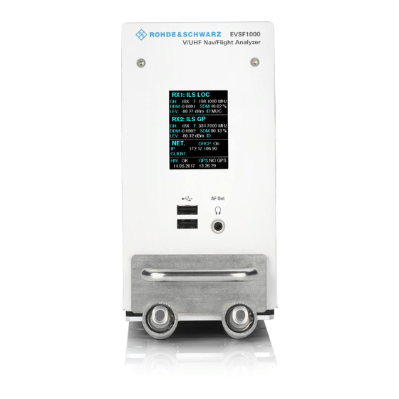
® Instrument Tour R&S EVSF1000 Front Panel Instrument Tour Front Panel This chapter describes the front panel, including all function keys and connectors. Figure 5-1: R&S EVSF1000 - Front panel view Getting Started 1178.6404.02 ─ 05... - Page 25 ® Instrument Tour R&S EVSF1000 Front Panel 1 = Display 2 = USB connectors 3 = AF Out 4 = Carrying handle 5.1.1 Display The display shows a basic set of measurement and configuration settings, includ- ing the currently used IP address for remote access. 5.1.2 USB Connectors The front panel provides two female USB connectors (USB-A, 2.0 standard) to...
- Page 26 ® Instrument Tour R&S EVSF1000 Rear Panel Rear Panel Figure 5-2: R&S EVSF1000 - Rear panel view (basic model, without R&S EVSF1-B4 option) 1 = Power Supply 2 = RX2 In 3 = LAN 4 = RS-232 GPS 5 = Device ID with serial number and other labels 6 = PPS In 7 = RX 1 In Getting Started 1178.6404.02 ─...
- Page 27 ® Instrument Tour R&S EVSF1000 Rear Panel If the R&S EVSF1000 is provided with the optional slide-in hardware R&S EVSF1-B4 installed, the rear panel has an ARINC connector instead of the individual connectors. See Chapter 5.2.6, "Optional ARINC Connec- tor (R&S EVSF1-B4)", on page 29.
-
Page 28: Power Supply
® Instrument Tour R&S EVSF1000 Rear Panel ● Trigger In (R&S EVSF1-B4 Only)..............32 ● IP-Address Select (R&S EVSF1-B4 Only)............32 ● Device ID......................32 5.2.1 Power Supply XLR connector for an external DC power source (11 V DC to 32 V DC). For details, refer to "Connecting to power"... -
Page 29: Pps In
® Instrument Tour R&S EVSF1000 Rear Panel 5.2.5 PPS In SMA connector with 1 MΩ impedance. Provides a PPS signal from an external GPS device for precise synchronization during data logging (requires option R&S EVSG-K20). If R&S EVSF1-B4 is installed, the PPS In interface is integrated in the ARINC connector (see Chapter 5.2.6, "Optional ARINC Connector (R&S EVSF1-B4)",... - Page 30 ® Instrument Tour R&S EVSF1000 Rear Panel Table 5-1: Pin assignment of ARINC connector Signal Description Cable type SPEAKER+/ Speaker/Audio out (AF Out) single, AWG 20-24 AUDIO SPEAKER-/ Speaker/Audio GND (AF Out) single, AWG 20-24 AUDIO_GND ADR_SEL_IN IP-Address-Select single, AWG 20-24 ETH_DO- LAN (Ethernet) 4x2 twisted paired,...
-
Page 31: Lf In
® Instrument Tour R&S EVSF1000 Rear Panel Signal Description Cable type V_DCIN_+28V Power single AWG 16-20 BB-IN Baseband-Input (LF-IN) single, AWG 20-24 GPS_GND RS232-GPS single, AWG 20-24 GPS_PPS_IN RS232-GPS PPS-IN single, AWG 20-24 GPS_RXD RS232-GPS single, AWG 20-24 RX1 (coaxial RX1 Antenna RG 223/ RG 142/ RG inlay) -
Page 32: Af Out (R&S Evsf1-B4 Only)
® Instrument Tour R&S EVSF1000 Rear Panel 5.2.9 AF Out (R&S EVSF1-B4 Only) Provides AF output to connected headphones or a loudspeaker (optimized for 8 Ω). When using the R&S EVSF1-Z2 service adapter, audio output is sent to the speaker. 5.2.10 Trigger In (R&S EVSF1-B4 Only) Provides an external trigger for data recording. - Page 33 ® Instrument Tour R&S EVSF1000 Accessories The serial number is used to define the default instrument name, which is: <Type><variant>-<serial_number> For example, EVSF1000-123456. The instrument name is required to establish a connection to the instrument in a LAN. Accessories Following accessories are available for rack installation: ●...
-
Page 34: Operating Basics
® Operating Basics R&S EVSF1000 Basic Configuration and Status Display Operating Basics The R&S EVSF1000 is designed for flight inspection and is thus optimized for remote operation, via predefined commands. It does not have a graphical user interface for manual interaction. Nevertheless, the instrument can also be controlled manually, by simulating a user interface on a remotely connected device, and using a connected keyboard. - Page 35 ® Operating Basics R&S EVSF1000 Basic Connection Settings Measurement information for each receiver board (RX1/RX2) In addition to the current measurement mode, measurement-specific information is provided. For example, for "ILS LOC" mode: ● "CH": Receiver channel ● "F": Receiver frequency ●...
- Page 36 ® Operating Basics R&S EVSF1000 Manual Operation from a VNC Viewer As an alternative, use the permanent instrument name to connect to the R&S EVSF1000. The default instrument name is a non-case-sensitive string with the following syntax: <Type><variant>-<serial_number> For example, EVSF1000-123456. For information on determining the serial number, see Chapter 5.2.12, "Device ID",...
- Page 37 ® Operating Basics R&S EVSF1000 Manual Operation from a VNC Viewer Figure 6-2: R&S EVSF1000 - GUI overview 1 = Measurement settings area (numeric modes only) 2 = Measurement result area 3 = Softkeys to edit settings and activate functions 4 = Status bar Measurement settings and results area During a measurement, the available settings are displayed at the top of the...
- Page 38 ® Operating Basics R&S EVSF1000 Manual Operation from a VNC Viewer Softkeys Softkeys are virtual function keys whose actual function is defined by the soft- ware, depending on the currently selected measurement mode or key, or both. Sometimes, more functions are available than softkeys can be displayed at the same time.
- Page 39 ® Operating Basics R&S EVSF1000 Manual Operation from a VNC Viewer Keyboard Usage Display Help Setup Mode Undo Redo PAGE UP Field right PAGE DOWN Field left Screenshot Meas Config Softkey 1 Softkey 2 Softkey 3 Softkey 4 Softkey 5 Softkey 6 Softkey 7 Show additional softkeys...
- Page 40 ® Operating Basics R&S EVSF1000 Manual Operation from a VNC Viewer Keyboard Usage BACKSPACE Back ENTER Enter Ampt BW (Bandwidth) Record Marker 6.3.3 Changing Settings and Activating Functions All functions available on the R&S EVSF1000 can be accessed using the keys on the external keyboard.
- Page 41 ® Operating Basics R&S EVSF1000 Manual Operation from a VNC Viewer 2. Select the key for the setting or function as required. If necessary, select [F8] to switch to the second softkey menu. The function is activated, or a new window is displayed to view or change spe- cific settings.
- Page 42 ® Operating Basics R&S EVSF1000 Manual Operation from a VNC Viewer All characters available via this key are displayed. 2. To choose another value provided by this key, press the key again, until your desired value is displayed. 3. With every key stroke, the next possible value of this key is displayed. If all possible values have been displayed, the series starts with the first value again.
- Page 43 ® Operating Basics R&S EVSF1000 Remote Control Table 6-2: Keys for alphanumeric parameters Key name Series of (special) characters and number provided (upper inscription) 7 µ Ω ° € ¥ $ ¢ A B C 8 Ä ÆÅ Ç D E F 9 É G H I 4 J K L 5 M N O 6 Ň...
-
Page 44: Contacting Customer Support
® Contacting Customer Support R&S EVSF1000 Contacting Customer Support Technical support – where and when you need it For quick, expert help with any Rohde & Schwarz product, contact our customer support center. A team of highly qualified engineers provides support and works with you to find a solution to your query on any aspect of the operation, program- ming or applications of Rohde &... -
Page 45: Index
® Index R&S EVSF1000 Index Accessories ..........33 USB connector ........25 AF Out ............. 25 User manual ..........10 Brochures ..........10 VNC Viewer ..........36 Customer support ........44 Data sheets ..........10 Front panel ..........24 Getting started ......... 10 RS-232 ..........28 Help ............
Need help?
Do you have a question about the R&S EVSF1000 and is the answer not in the manual?
Questions and answers