Rohde & Schwarz EVSG1000 Getting Started
Vhf/uhf airnav/com analyzer
Hide thumbs
Also See for EVSG1000:
- User manual (311 pages) ,
- Getting started (52 pages) ,
- User manual (418 pages)

Subscribe to Our Youtube Channel
Related Manuals for Rohde & Schwarz EVSG1000


Summary of Contents for Rohde & Schwarz EVSG1000
- Page 1 ® R&S EVSG1000 VHF/UHF Airnav/Com Analyzer Getting Started (=MåE2) 1329872102 Version 05...
- Page 2 This document describes the following R&S EVSG1000 models with firmware version 1.50 or later: ● R&S EVSG1000 VHF/UHF nav/drone analyzer (1330.0350K02) ● R&S ® EVSG1000 (1329.8009.02) Furthermore, it covers the following options: ● R&S EVSG-B1 Second Signal Processing Unit (1329.8809.02) ●...
-
Page 3: Table Of Contents
4.1 Unpacking and checking..............15 4.2 Lifting and carrying................15 4.3 Setting up the R&S EVSG1000............16 4.3.1 Placing the R&S EVSG1000 on a bench top........16 4.3.2 Mounting the R&S EVSG1000 in a rack..........16 4.3.3 Portable operation.................17 4.4 Connecting to power................17 4.4.1 Connecting the provided AC/DC power supply connector....18... - Page 4 ® Contents R&S EVSG1000 4.5 Switching on or off................20 4.6 Connecting devices for signal input and output......22 4.7 Connecting to LAN................22 4.8 Setting up a data link (Wi-Fi) connection..........24 4.9 Performing an autocalibration............25 5 Instrument tour..............26 5.1 Front panel..................
- Page 5 ® Contents R&S EVSG1000 5.2.8 Demod out.................... 34 5.2.9 Loudspeaker..................34 5.2.10 Device ID....................35 5.3 Accessories..................35 6 Operating basics..............39 6.1 Understanding the display information..........39 6.2 Manual operation................41 6.2.1 Changing settings and activating functions...........42 6.2.2 Entering data..................42 6.2.3 Getting help...................44 6.3 Manual operation from a VNC viewer..........
- Page 6 ® Contents R&S EVSG1000 Getting Started 1329.8721.02 ─ 05...
-
Page 7: Safety Information
Intended use The R&S EVSG1000 is a signal level and modulation analyzer to be used on the ground. It performs measurements on instrument landing systems (ILS), ground- based augmentation systems (GBAS), very high frequency omnidirectional range (VOR) and marker beacon ground stations. -
Page 8: Safety Instructions
® Safety information R&S EVSG1000 Safety instructions Safety instructions Products from the Rohde & Schwarz group of companies are manufactured according to the highest technical standards. To use the products safely, follow the instructions provided here and in the product documentation. Keep the prod- uct documentation nearby and offer it to other users. - Page 9 ® Safety information R&S EVSG1000 Safety instructions Connecting to power The product runs on DC voltage. For the specifications of the supply voltage for the product, refer to the data sheet. Under normal conditions, contact with DC voltage in this range poses a low risk of electric shock.
-
Page 10: Labels On The Product
® Safety information R&S EVSG1000 Labels on the product ● Dispose of exchangeable batteries separately from normal household waste as specified by the local waste disposal agency. If you disregard these rules, you risk serious personal injury or even death due to explosion, fire or hazardous chemical substances. -
Page 11: Warning Messages In The Documentation
Labeling in line with EN 50419 for disposal of electrical and electronic equipment after the product has come to the end of its service life. For more information, see the R&S EVSG1000 user manual, chapter "Disposal". Labeling in line with directive 2006/66/EC for disposal of batteries after they have come to the end of their service life. -
Page 12: Documentation Overview
Further documents are available at: www.rohde-schwarz.com/product/EVSG Getting started manual Introduces the R&S EVSG1000 and describes how to set up and start working with the product. A printed version is delivered with the instrument. User manuals and help Contains the description of all instrument modes and functions. It also provides... -
Page 13: Printed Safety Instructions
Provides safety information in many languages. The printed document is deliv- ered with the product. Data sheets and brochures The data sheet contains the technical specifications of the R&S EVSG1000. It also lists the firmware applications and their order numbers, and optional acces- sories. -
Page 14: Key Features
R&S EVSG1000 Key features The R&S EVSG1000 offers the following key features: ● Detailed analysis of ILS, VOR and Marker Beacon ground measurements (based on ICAO Doc. 8071 and ICAO Annex 10) ● Spectrum preview and detailed signal analysis in frequency and time range ●... -
Page 15: Preparing For Use
● Performing an autocalibration................. 25 Unpacking and checking 1. Unpack the R&S EVSG1000 carefully. 2. Retain the original packing material. Use it when transporting or shipping the product later. 3. Using the delivery notes, check the equipment for completeness. The instrument comes with the following accessories: ●... -
Page 16: Setting Up The R&S Evsg1000
Setting up the R&S EVSG1000 Setting up the R&S EVSG1000 The R&S EVSG1000 is designed for use either on a bench top or in a rack, or as a portable instrument (with optional battery operation) in a transport bag in the field. -
Page 17: Portable Operation
1. Loosen the screws at the rack brackets. 2. Remove the R&S EVSG1000 from the rack. 3. If placing the R&S EVSG1000 on a bench top again, unmount the adapter kit from the R&S EVSG1000. Follow the instructions provided with the adapter kit. -
Page 18: Connecting The Provided Ac/Dc Power Supply Connector
4.4.1 Connecting the provided AC/DC power supply connector To operate the R&S EVSG1000 on a 230 V AC power supply, use only the provi- ded AC/DC power supply connector. 1. Connect the DC connector on the provided AC/DC power supply connector to the Power Supply connector on the back of the R&S EVSG1000 (see... -
Page 19: Using An Optional Battery Pack
4.4.3 Using an optional battery pack As an alternative to the fixed AC or DC power supply, the R&S EVSG1000 can be operated by a battery pack, if the R&S EVSG-B2 Battery Management and R&S EVSG-B3 Battery Pack options are installed. Use only the original battery pack R&S EVSG-B3 Battery Pack. -
Page 20: Switching On Or Off
R&S EVSG1000 Switching on or off When charging the battery, observe the following: ● For charging, use only the R&S EVSG1000 or the R&S ® FSV-B34 battery charger (1321.3950.02). ● If the instrument is connected to the provided AC/DC power supply connector... - Page 21 27. The left power LED starts blinking. The instrument boots. The boot process of the R&S EVSG1000 takes about 30 seconds. Then the instrument automatically starts the measurement mode used before the instru- ment was switched off. The power LED stops blinking.
-
Page 22: Connecting Devices For Signal Input And Output
Connecting to LAN Risk of data loss If you disconnect the R&S EVSG1000 from power when it is switched on and no (charged) battery is installed, you can lose settings and data. Switch off the instrument before disconnecting it from power. - Page 23 ● Changing IP addresses ● Exchanging hardware Errors can affect the entire network. 1. Connect the R&S EVSG1000 to the LAN via the LAN interface on the right panel of the instrument. 2. Start a VNC client on the connected remote device.
-
Page 24: Setting Up A Data Link (Wi-Fi) Connection
The R&S EVSG1000 is configured as a Wi-Fi access point using a DHCP server. By default, the following settings are defined. 2. Usually, you can access the R&S EVSG1000 using the default IP address and Wi-Fi password without further configuration. The default IP address is 192.168.1.1. -
Page 25: Performing An Autocalibration
For details, see the R&S EVSG1000 user manual. Performing an autocalibration After setting up the R&S EVSG1000, perform an autocalibration to ensure the accuracy of the measurements. After initial setup, it is recommended that you perform an autocalibration every 2 months or if the difference of the environment temperature changes by more than 10 °C. -
Page 26: Instrument Tour
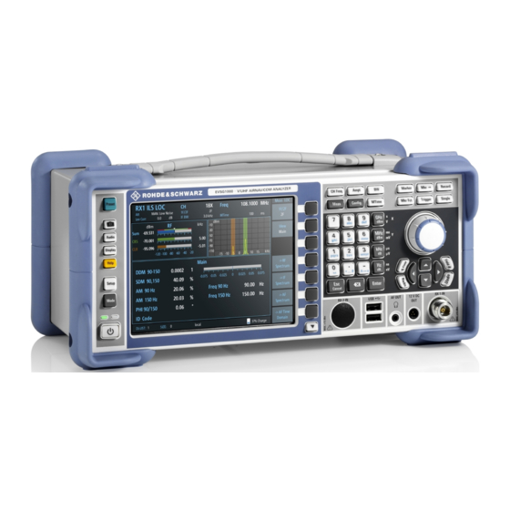
Front panel Instrument tour Front panel This chapter describes the front panel, including all function keys and connectors. Figure 5-1: R&S EVSG1000 - Front panel view 1 = Power key 2 = System keys 3 = Display 4 = Softkeys... -
Page 27: Power Key
The RX input connectors are 50 Ω N connectors. Use the RX inputs to connect a receiving antenna (max. +13 dBm) to the R&S EVSG1000 for RF signal input. "RX2 In" is supplied as an option (R&S EVSG-B1 Second Signal Processing Unit). -
Page 28: Usb
® Instrument tour R&S EVSG1000 Front panel 5.1.4 The front panel provides two female USB connectors (USB-A, 2.0 standard) to connect a memory device. The memory device is used to store and reload instrument settings, to provide software updates and to export measurement data. -
Page 29: Softkeys
® Instrument tour R&S EVSG1000 Front panel 5.1.8 Softkeys Softkeys are virtual keys provided by the software. Thus, more functions can be provided than those that can be accessed directly via the function keys on the instrument. Softkeys are dynamic, i.e. depending on the selected function key, a different list of softkeys is displayed on the right side of the screen. -
Page 30: 5.1.10 Keypad
® Instrument tour R&S EVSG1000 Front panel 5.1.10 Keypad The keypad is used to enter numeric parameters, including the corresponding units. It contains the following keys. Type of key Description Decimal point Inserts a decimal point "." at the cursor posi- tion. -
Page 31: 5.1.12 Navigation Keys
® Instrument tour R&S EVSG1000 Front panel ● In lists: toggles between entries ● For markers, limit lines, and other graphical elements on the screen: moves their position ● For active scroll bars: moves the scroll bar vertically ● For dialog boxes: Acts like the ENTER key when pressed While you turn the rotary knob, the settings are applied immediately, and the results are updated accordingly. -
Page 32: Rear Panel
® Instrument tour R&S EVSG1000 Rear panel Rear panel Figure 5-2: R&S EVSG1000 - Rear panel view 1 = Loudspeaker 2 = Li-Ion battery pack 3 = USB 4 = LAN 5 = RS232-GPS 6 = PPS In 7 = Trigger In... -
Page 33: Power Supply
5.2.3 LAN (ethernet) Through the LAN connection (Fast Ethernet), all functions of the R&S EVSG1000 can be remotely operated. The LAN connection can also be used to stream mea- surement data (TCP port 8000; for I/Q data: 8001 (RX1) or 8002 (RX2)). IP Addresses and subnet mask are defined in the setup menu. -
Page 34: Rs232 Gps
BNC socket, 50 Ω/20 kΩ to input an AF signal or signals with a very low IF (<25 kHz) to the R&S EVSG1000 for further analysis of typical AF parameters. Furthermore, LF input allows for analysis of non-directional beacon (NDB) signals from 190 kHz to 1750 kHz. -
Page 35: 5.2.10 Device Id
● Weather protection bag (R&S EVSG-Z1 carrying bag) The weather protection bag has a transparent cover that allows you to use the R&S EVSG1000 in the field even under adverse weather conditions. The front pocket can be used to transport accessories, such as the external power sup- ply. - Page 36 ® Instrument tour R&S EVSG1000 Accessories Figure 5-3: Weather protection bag ● Rugged Transport case (R&S EVSG-Z2 Rugged transport case) A hard-top case with trolley functionality. Figure 5-4: Transport Case ● ILS / VOR Dipole Antenna (R&S EVS-Z3) The lightweight design of the ILS/VOR dipole antenna and its compact size makes this antenna ideal for mobile measurements in the field.
- Page 37 ® Instrument tour R&S EVSG1000 Accessories Figure 5-5: ILS / VOR Dipole Antenna ● Antenna bag (R&S EVS-Z4) The carrying bag allows you to transport all the antenna elements and the telescopic mast safely. Figure 5-6: Antenna bag ● Display protection cover (R&S EVS-Z6) The protective hard cover protects the front panel during transport.
- Page 38 Instrument tour R&S EVSG1000 Accessories Figure 5-7: Display protection cover ● 19''-adapter (R&S EVSG-Z7 rack adapter kit) This option is required to mount the R&S EVSG1000 in a 19'' rack (e.g. in a measurement vehicle). Getting Started 1329.8721.02 ─ 05...
-
Page 39: Operating Basics
This chapter provides an overview on how to work with the R&S EVSG1000. It describes what kind of information is displayed on the screen and how to operate the R&S EVSG1000 manually and remotely. - Page 40 Operating basics R&S EVSG1000 Understanding the display information Figure 6-1: R&S EVSG1000 - GUI overview 1 = Measurement settings area (numeric modes only) 2 = Measurement result area 3 = Softkeys to edit settings and activate functions 4 = Status bar...
-
Page 41: Manual Operation
● Battery status and charge status (in %) Manual operation This chapter describes how to operate the R&S EVSG1000 directly on the instru- ment, using graphical interaction methods. During manual operation, the R&S EVSG1000 display indicates "Local" in the status bar. -
Page 42: Changing Settings And Activating Functions
6.2.1 Changing settings and activating functions All functions available on the R&S EVSG1000 can be accessed using the keys on the front panel of the instrument. Some keys provide a softkey menu on the dis- play with further functions and settings. - Page 43 ® Operating basics R&S EVSG1000 Manual operation Entering numeric parameters If a field requires numeric input, the keypad provides only numbers. 1. Enter the parameter value using the keypad, or change the currently used parameter value by turning the rotary knob or pressing the Up or Down arrow keys.
-
Page 44: Getting Help
<toggles between capital and small letters> 6.2.3 Getting help If any questions or problems concerning the R&S EVSG1000 arise, an online help system is provided on the instrument and can be consulted at any time. Displaying the online help system on the instrument 1. - Page 45 ® Operating basics R&S EVSG1000 Manual operation 2. Press [Enter] to display the user manual contents. Getting Started 1329.8721.02 ─ 05...
- Page 46 ® Operating basics R&S EVSG1000 Manual operation Navigating in the help system To move up and down ► Use the arrow keys. To switch between areas ► Press the Field left and Field right keys. VNC: Press the [PAGE UP] and [PAGE DOWN] keys.
-
Page 47: Manual Operation From A Vnc Viewer
Using a VNC viewer application, you simply connect to the instrument, defined by its IP address. The display of the R&S EVSG1000 is shown on the control PC. The keys and other graphical user interface elements are operated using associ- ated keyboard shortcuts on the connected keyboard. - Page 48 ® Operating basics R&S EVSG1000 Manual operation from a VNC viewer Keyboard Usage PAGE UP Field right PAGE DOWN Field left Screenshot Meas Config Softkey 1 Softkey 2 Softkey 3 Softkey 4 Softkey 5 Softkey 6 Softkey 7 Show additional softkeys...
-
Page 49: Remote Control
You define the IP address and subnet mask in the "Setup" menu. Remote control is performed using predefined remote commands which are sent from the control device to the R&S EVSG1000. The R&S EVSG1000 can also return queried data to the control device. -
Page 50: Contacting Customer Support
® Contacting customer support R&S EVSG1000 Contacting customer support Technical support – where and when you need it For quick, expert help with any Rohde & Schwarz product, contact our customer support center. A team of highly qualified engineers provides support and works with you to find a solution to your query on any aspect of the operation, program- ming or applications of Rohde &... -
Page 51: Index
® Index R&S EVSG1000 Index Accessories ..........35 Rear Panel ..........32 Adapter, 19'' ........38 Release notes ......... 13 Antenna ..........36 Antenna bag ........37 Display protection cover ..... 37 Safety instructions ....... 8, 13 R&S EVS-Z3 ........36 Service manual ........12...
Need help?
Do you have a question about the EVSG1000 and is the answer not in the manual?
Questions and answers