Rohde & Schwarz R&S EVSG1000 Getting Started
Vhf/uhf airnav/com analyzer
Hide thumbs
Also See for R&S EVSG1000:
- User manual (311 pages) ,
- User manual (418 pages) ,
- Getting started (51 pages)
Table of Contents
Advertisement
Quick Links
Advertisement
Table of Contents

Related Manuals for Rohde & Schwarz R&S EVSG1000


Summary of Contents for Rohde & Schwarz R&S EVSG1000
- Page 1 ® R&S EVSG1000 VHF/UHF Airnav/Com Analyzer Getting Started (=MåE2) 1329872102...
- Page 2 ® This document describes the following R&S EVSG1000 models with firmware version 1.40 or later: ● R&S ® EVSG1000 (1329.8009.02) Furthermore, it covers the following options: ● R&S ® EVSG-B1 Second Signal Processing Unit (1329.8809.02) ● R&S ® EVSG-B2 Battery Management (1329.8815.02) ●...
-
Page 3: Table Of Contents
® Contents R&S EVSG1000 Contents 1 Safety Information..............7 1.1 Safety Instructions................7 1.2 Labels on the Product................ 11 1.3 Warning Messages in the Documentation........12 2 Documentation Overview............13 2.1 Getting Started Manual...............13 2.2 User Manuals and Help..............13 2.3 Printed Safety Instructions..............13 2.4 Data Sheets and Brochures............... - Page 4 ® Contents R&S EVSG1000 4.7 Performing an Auto-Calibration............24 4.8 Connecting Devices for Signal Input and Output......25 4.9 Connecting to LAN................25 5 Instrument Tour..............27 5.1 Front Panel..................27 5.1.1 Power Key.....................28 5.1.2 Display....................28 5.1.3 RX1 IN / RX2 IN..................28 5.1.4 USB.......................29 5.1.5 AF Out....................29 5.1.6 12 V DC Out..................29...
- Page 5 ® Contents R&S EVSG1000 5.2.10 Device ID....................36 5.3 Accessories..................36 6 Operating Basics..............40 6.1 Understanding the Display Information..........40 6.2 Manual Operation................42 6.2.1 Changing Settings and Activating Functions........43 6.2.2 Entering Data..................43 6.2.3 Getting Help..................45 6.3 Manual Operation from a VNC Viewer..........48 6.4 Remote Control...................
- Page 6 ® Contents R&S EVSG1000 Getting Started 1329.8721.02 ─ 04...
-
Page 7: Safety Information
® Safety Information R&S EVSG1000 Safety Instructions Safety Information The product documentation helps you use the product safely and efficiently. Fol- low the instructions provided here and in the Chapter 1.1, "Safety Instructions", on page 7. Intended use The product is intended for maintenance and servicing of ILS, VOR and marker beacon ground stations and analyzing ATC COM signals. - Page 8 ® Safety Information R&S EVSG1000 Safety Instructions Using the product requires specialists or specially trained personnel. These users also need sound knowledge of at least one of the languages in which the user interfaces and the product documentation are available. If any part of the product is damaged or broken, stop using the product.
- Page 9 ® Safety Information R&S EVSG1000 Safety Instructions the products from the bottom shelf to the top shelf so that the rack stands securely. Secure the product so that it cannot fall off the rack. Connecting to power The product is an overvoltage category II product and has to be connected to a fixed installation used to supply energy-consuming equipment such as household appliances and similar loads.
- Page 10 ® Safety Information R&S EVSG1000 Safety Instructions Meaning of safety labels Safety labels on the product warn against potential hazards. Potential hazard Read the product documentation to avoid personal injury or product damage. Electrical hazard Indicates live parts. Risk of electric shock, fire, personal injury or even death. Hot surface Do not touch.
-
Page 11: Labels On The Product
® Safety Information R&S EVSG1000 Labels on the Product ● Store the battery at room temperature (approximately 20 °C) enclosed in the original packaging. ● Dispose of batteries separately from normal household waste as specified by the local waste disposal agency. If you disregard these rules, you risk serious personal injury or even death due to explosion, fire or hazardous chemical substances. -
Page 12: Warning Messages In The Documentation
® Safety Information R&S EVSG1000 Warning Messages in the Documentation Warning Messages in the Documentation A warning message points out a risk or danger that you need to be aware of. The signal word indicates the severity of the safety hazard and how likely it will occur if you do not follow the safety precautions. -
Page 13: Documentation Overview
® Documentation Overview R&S EVSG1000 Data Sheets and Brochures Documentation Overview This section provides an overview of the R&S EVSG1000 user documentation. You find it on the product page at: www.rohde-schwarz.com/manual/EVSG1000 Getting Started Manual Introduces the R&S EVSG1000 and describes how to set up and start working with the product. -
Page 14: Release Notes And Open-Source Acknowledgment (Osa)
® Documentation Overview R&S EVSG1000 Release Notes and Open-Source Acknowledgment (OSA) The brochure provides an overview of the instrument and deals with the specific characteristics. www.rohde-schwarz.com/brochure-datasheet/evsg/ Release Notes and Open-Source Acknowledg- ment (OSA) The release notes list new features, improvements and known issues of the cur- rent firmware version, and describe the firmware installation. -
Page 15: Key Features
® Key Features R&S EVSG1000 Key Features The R&S EVSG1000 offers the following key features: ● Detailed analysis of ILS, VOR and Marker Beacon ground measurements (based on ICAO Doc. 8071 and ICAO Annex 10) ● Spectrum preview and detailed signal analysis in frequency and time range ●... -
Page 16: Preparing For Use
® Preparing for Use R&S EVSG1000 Lifting and Carrying Preparing for Use This chapter describes the basic steps to be taken when setting up the product for the first time. ● Unpacking and Checking................16 ● Lifting and Carrying..................16 ●... -
Page 17: Choosing The Operating Site
® Preparing for Use R&S EVSG1000 Setting Up the R&S EVSG1000 "Lifting and carrying the product" on page 8. Choosing the Operating Site The R&S EVSG1000 can be operated in a variety of places without detrimental effects on its features. Even the movement caused by transportation or mobile use does not impair its functioning. -
Page 18: Placing The R&S Evsg1000 On A Bench Top
® Preparing for Use R&S EVSG1000 Setting Up the R&S EVSG1000 ● "Intended use" on page 7 4.4.1 Placing the R&S EVSG1000 on a Bench Top To place the R&S EVSG1000 on a bench top 1. Place the R&S EVSG1000 on a stable, flat and level surface. Ensure that the surface can support the weight of the instrument. -
Page 19: Portable Operation
® Preparing for Use R&S EVSG1000 Setting Up the R&S EVSG1000 2. NOTICE! Insufficient airflow can cause overheating and damage the product. Design and implement an efficient ventilation concept for the rack. To mount the R&S EVSG1000 in a rack 1. -
Page 20: Connecting To Power
® Preparing for Use R&S EVSG1000 Connecting to Power the dedicated carrying bag, the R&S EVSG1000 is ideally suited for operation directly in the field, even in rough environments. See also Chapter 4.2, "Lifting and Carrying", on page 16. Connecting to Power To ensure high mobility and flexibility while using the R&S EVSG1000, it is equip- ped with a DC power supply connector on the rear panel of the instrument. -
Page 21: Connecting An External Dc Power Source
® Preparing for Use R&S EVSG1000 Connecting to Power The green Power LED on the front panel of the R&S EVSG1000 lights up. 4.5.2 Connecting an External DC Power Source The R&S EVSG1000 can be operated directly from an external DC power source with a voltage of 10 V DC to 28 V DC and a current of 3.0 A. -
Page 22: Switching On Or Off
® Preparing for Use R&S EVSG1000 Switching On or Off For information on how to exchange a battery pack, see the R&S EVSG1000 user manual, chapter "Maintenance". If the battery pack is installed and no DC power is supplied, the R&S EVSG1000 automatically switches to battery operation. - Page 23 ® Preparing for Use R&S EVSG1000 Switching On or Off Table 4-1: Overview of operating states Status gray Booting green, blinking Ready for operation green The right LED indicates the power state: Table 4-2: Overview of power states Status Not connected to power gray Connected to power green...
-
Page 24: Performing An Auto-Calibration
® Preparing for Use R&S EVSG1000 Performing an Auto-Calibration To disconnect from power The instrument is switched off. Risk of data loss If you disconnect the R&S EVSG1000 from power when it is switched on and no (charged) battery is installed, you can lose settings and data. Switch off the instrument before disconnecting it from power. -
Page 25: Connecting Devices For Signal Input And Output
® Preparing for Use R&S EVSG1000 Connecting to LAN 3. Press [Enter]. The "Setup - CAL" display shows the status for each calibration step. When completed, after a few minutes, all entries must have the status "OK". For more information on auto-calibration, see the R&S EVSG1000 user manual. Connecting Devices for Signal Input and Output Information on signal levels is provided in the data sheet. - Page 26 ® Preparing for Use R&S EVSG1000 Connecting to LAN Risk of network failure Consult your network administrator before performing the following tasks: ● Connecting the instrument to the network ● Configuring the network ● Changing IP addresses ● Exchanging hardware Errors can affect the entire network.
-
Page 27: Instrument Tour
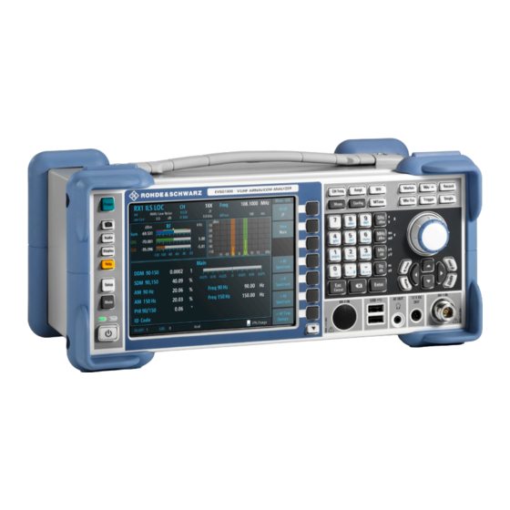
® Instrument Tour R&S EVSG1000 Front Panel Instrument Tour Front Panel This chapter describes the front panel, including all function keys and connectors. Figure 5-1: R&S EVSG1000 - Front panel view 1 = Power key 2 = System keys 3 = Display 4 = Softkeys 5 = Keypad 6 = Function keys... -
Page 28: Power Key
® Instrument Tour R&S EVSG1000 Front Panel ● Power Key.......................28 ● Display......................28 ● RX1 IN / RX2 IN....................28 ● USB.........................29 ● Out......................29 ● 12 V DC Out....................29 ● System Keys....................29 ● Softkeys......................30 ● Function Keys....................30 ●... -
Page 29: Usb
® Instrument Tour R&S EVSG1000 Front Panel 5.1.4 The front panel provides two female USB connectors (USB-A, 2.0 standard) to connect a memory device. The memory device is used to store and reload instrument settings, to provide software updates and to export measurement data. 5.1.5 AF Out Connector for a headset with a 3.5 mm jack plug... -
Page 30: Softkeys
® Instrument Tour R&S EVSG1000 Front Panel 5.1.8 Softkeys Softkeys are virtual keys provided by the software. Thus, more functions can be provided than those that can be accessed directly via the function keys on the instrument. Softkeys are dynamic, i.e. depending on the selected function key, a different list of softkeys is displayed on the right side of the screen. -
Page 31: 5.1.10 Keypad
® Instrument Tour R&S EVSG1000 Front Panel 5.1.10 Keypad The keypad is used to enter numeric parameters, including the corresponding units. It contains the following keys. Type of key Description Decimal point Inserts a decimal point "." at the cursor posi- tion. -
Page 32: 5.1.12 Navigation Keys
® Instrument Tour R&S EVSG1000 Front Panel ● In lists: toggles between entries ● For markers, limit lines, and other graphical elements on the screen: moves their position ● For active scroll bars: moves the scroll bar vertically ● For dialog boxes: Acts like the ENTER key when pressed While you turn the rotary knob, the settings are applied immediately, and the results are updated accordingly. -
Page 33: Rear Panel
® Instrument Tour R&S EVSG1000 Rear Panel Rear Panel Figure 5-2: R&S EVSG1000 - Rear panel view 1 = Loudspeaker 2 = Li-Ion battery pack 3 = USB 4 = LAN 5 = RS232-GPS 6 = PPS In 7 = Trigger In 8 = LF In 9 = Demod Out 10 = Power Supply... -
Page 34: Power Supply
® Instrument Tour R&S EVSG1000 Rear Panel ● Demod Out......................35 ● Loudspeaker....................35 ● Device ID......................36 5.2.1 Power Supply XLR connector for an external DC power source (10 V DC to 28 V DC) For details, refer to "Connecting to power" on page 9 and Chapter 4.5, "Connect- ing to... -
Page 35: Rs232 Gps
® Instrument Tour R&S EVSG1000 Rear Panel 5.2.4 RS232 GPS 2-port RS232, 9-pin D-Sub connector for a GPS receiver providing NMEA proto- col data. The NMEA protocol data is displayed and stored with the recorded data (requires option R&S EVSG-K20). 5.2.5 PPS In SMA connector with 1 MΩ... -
Page 36: 5.2.10 Device Id
® Instrument Tour R&S EVSG1000 Accessories 5.2.10 Device ID The unique device identifier is provided as a barcode sticker on the rear panel of the R&S EVSG1000. It consists of the device order number and a serial number. The serial number is used to define the default instrument name, which is: <Type><variant>-<serial_number>... - Page 37 ® Instrument Tour R&S EVSG1000 Accessories Figure 5-3: Weather protection bag ● Rugged Transport case (R&S EVSG-Z2) A hard-top case with trolley functionality. Figure 5-4: Transport Case ● ILS / VOR Dipole Antenna (R&S EVS-Z3) The lightweight design of the ILS/VOR dipole antenna and its compact size makes this antenna ideal for mobile measurements in the field.
- Page 38 ® Instrument Tour R&S EVSG1000 Accessories Figure 5-5: ILS / VOR Dipole Antenna ● Antenna bag (R&S EVS-Z4) The carrying bag allows you to transport all the antenna elements and the telescopic mast safely. Figure 5-6: Antenna bag ● Display protection cover (R&S EVS-Z6) The protective hard cover protects the front panel during transport.
- Page 39 ® Instrument Tour R&S EVSG1000 Accessories Figure 5-7: Display protection cover ● 19''-adapter (R&S EVSG-Z7) This option is required to mount the R&S EVSG1000 in a 19'' rack (e.g. in a measurement vehicle). Getting Started 1329.8721.02 ─ 04...
-
Page 40: Operating Basics
® Operating Basics R&S EVSG1000 Understanding the Display Information Operating Basics The R&S EVSG1000 is designed for ground inspection and is thus optimized for manual operation, via the graphical user interface. Nevertheless, the instrument can also be controlled remotely, either by executing predefined commands, or by simulating the user interface on a remotely connec- ted device. - Page 41 ® Operating Basics R&S EVSG1000 Understanding the Display Information Figure 6-1: R&S EVSG1000 - GUI overview 1 = Measurement settings area (numeric modes only) 2 = Measurement result area 3 = Softkeys to edit settings and activate functions 4 = Status bar Measurement settings and results area During a measurement, the available settings are displayed at the top of the screen;...
-
Page 42: Manual Operation
® Operating Basics R&S EVSG1000 Manual Operation Softkeys Softkeys are virtual function keys whose actual function is defined by the soft- ware, depending on the currently selected measurement mode or key, or both. Sometimes, more functions are available than softkeys can be displayed at the same time. -
Page 43: Changing Settings And Activating Functions
® Operating Basics R&S EVSG1000 Manual Operation 6.2.1 Changing Settings and Activating Functions All functions available on the R&S EVSG1000 can be accessed using the keys on the front panel of the instrument. Some keys provide a softkey menu on the dis- play with further functions and settings. - Page 44 ® Operating Basics R&S EVSG1000 Manual Operation Entering numeric parameters If a field requires numeric input, the keypad provides only numbers. 1. Enter the parameter value using the keypad, or change the currently used parameter value by turning the rotary knob or pressing the Up or Down arrow keys.
-
Page 45: Getting Help
® Operating Basics R&S EVSG1000 Manual Operation 2. Press the [BACK] key. The entry to the left of the cursor is deleted. 3. Enter your correction. Completing the entry ► Press the [ENTER] key or the rotary knob. For numeric values, the default unit is appended to the numeric input. To enter a value using a different unit, select the corresponding key. - Page 46 ® Operating Basics R&S EVSG1000 Manual Operation Displaying the online help system on the instrument 1. Press the [Help] key on the front panel. 2. Press [Enter] to display the user manual contents. Getting Started 1329.8721.02 ─ 04...
- Page 47 ® Operating Basics R&S EVSG1000 Manual Operation Navigating in the help system To move up and down ► Use the arrow keys. To switch between areas ► Press the Field left and Field right keys. VNC: Press the [PAGE UP] and [PAGE DOWN] keys. To follow a link ►...
-
Page 48: Manual Operation From A Vnc Viewer
® Operating Basics R&S EVSG1000 Manual Operation from a VNC Viewer To exit the online help and return to the firmware view ► Press [ESC]. Manual Operation from a VNC Viewer As an alternative to operating the R&S EVSG1000 directly on the instrument, you can perform the same tasks from a connected PC using a keyboard. - Page 49 ® Operating Basics R&S EVSG1000 Manual Operation from a VNC Viewer Keyboard Usage PAGE UP Field right PAGE DOWN Field left Screenshot Meas Config Softkey 1 Softkey 2 Softkey 3 Softkey 4 Softkey 5 Softkey 6 Softkey 7 Show additional softkeys Trigger Single CH/FREQ...
-
Page 50: Remote Control
® Operating Basics R&S EVSG1000 Remote Control Keyboard Usage Ampt BW (Bandwidth) Record Marker Remote Control You can control the R&S EVSG1000, including data transfer, remotely from a PC using the LAN connection (Fast Ethernet). You define the IP address and subnet mask in the "Setup" menu. Remote control is performed using predefined remote commands which are sent from the control PC to the R&S EVSG1000. -
Page 51: Contacting Customer Support
® Contacting Customer Support R&S EVSG1000 Contacting Customer Support Technical support – where and when you need it For quick, expert help with any Rohde & Schwarz product, contact our customer support center. A team of highly qualified engineers provides support and works with you to find a solution to your query on any aspect of the operation, program- ming or applications of Rohde &... -
Page 52: Index
® Index R&S EVSG1000 Index Release notes ......... 14 Accessories ..........36 Adapter, 19'' ........39 Safety instructions ........13 Antenna ..........37 Antenna bag ........38 Display protection cover ..... 38 User manual ..........13 R&S EVS-Z3 ........37 R&S EVS-Z4 ........
Need help?
Do you have a question about the R&S EVSG1000 and is the answer not in the manual?
Questions and answers