Rohde & Schwarz EVSF1000 Getting Started
Hide thumbs
Also See for EVSF1000:
- User manual (295 pages) ,
- Getting started (33 pages) ,
- Getting started (45 pages)

Subscribe to Our Youtube Channel
Related Manuals for Rohde & Schwarz EVSF1000


Summary of Contents for Rohde & Schwarz EVSF1000
- Page 1 ® R&S EVSF1000 VHF/UHF Nav/Flight Analyzer Getting Started (;ÜÎ42) 1178640402 Version 06...
- Page 2 This document describes the following R&S EVSF1000 models with firmware ver- sion 1.50 or later: ● R&S EVSF1000 VHF/UHF nav/drone analyzer (1330.0350K02) ● R&S EVSF1000 (1330.0008.02) Furthermore, it covers the following options: ● R&S EVSF1-B4 (1330.1404.02) ● R&S EVSF1-Z1 (1330.1410.02) ●...
-
Page 3: Table Of Contents
® Contents R&S EVSF1000 Contents 1 Safety information..............5 2 Documentation overview............9 3 Key features................. 11 4 Preparing for use..............12 5 Instrument tour..............23 6 Operating basics..............33 7 Contacting customer support..........43 Index..................44 Getting Started 1178.6404.02 ─ 06... - Page 4 ® Contents R&S EVSF1000 Getting Started 1178.6404.02 ─ 06...
-
Page 5: Safety Information
Intended use The R&S EVSF1000 is a level and modulation analyzer intended for installation in flight inspection aircraft. It performs measurements on instrument landing sys- tems (ILS), ground-based augmentation systems (GBAS), very high frequency omnidirectional range (VOR) and marker beacon ground stations. - Page 6 ® Safety information R&S EVSF1000 Safety instructions Safety instructions Products from the Rohde & Schwarz group of companies are manufactured according to the highest technical standards. To use the products safely, follow the instructions provided here and in the product documentation. Keep the prod- uct documentation nearby and offer it to other users.
- Page 7 ® Safety information R&S EVSF1000 Labels on the product Connecting to power The product runs on DC voltage. For the specifications of the supply voltage for the product, refer to the data sheet. Under normal conditions, contact with DC voltage in this range poses a low risk of electric shock.
- Page 8 Labeling in line with EN 50419 for disposal of electrical and electronic equipment after the product has come to the end of its service life. For more information, see the R&S EVSF1000 user manual, chapter "Disposal". Warning messages in the documentation A warning message points out a risk or danger that you need to be aware of.
-
Page 9: Documentation Overview
Further documents are available at: www.rohde-schwarz.com/product/EVSF1000 Getting started manual Introduces the R&S EVSF1000 and describes how to set up and start working with the product. A printed version is delivered with the instrument. User manuals and help Contains the description of all instrument modes and functions. It also provides... - Page 10 Provides safety information in many languages. The printed document is deliv- ered with the product. Data sheets and brochures The data sheet contains the technical specifications of the R&S EVSF1000. It also lists the firmware applications and their order numbers, and optional acces- sories.
-
Page 11: Key Features
R&S EVSF1000 Key features The R&S EVSF1000 offers the following key features: ● Detailed analysis of ILS, VOR and Marker Beacon ground measurements (based on ICAO Doc. 8071 and ICAO Annex 10) ● Analysis of air traffic control (ATC) communications signals ●... -
Page 12: Preparing For Use
If the delivery is incomplete or equipment is damaged, contact Rohde & Schwarz. Lifting and carrying The handle on the front of the R&S EVSF1000 is designed to move, lift or carry the instrument. Do not apply excessive external force to the handle. Getting Started 1178.6404.02 ─ 06... -
Page 13: Setting Up The Product
4.3.1 Mounting the R&S EVSF1000 in a rack The R&S EVSF1000 is meant for use in a flight inspection plane. Make sure that the product is properly secured. For a stable setup, you can connect the R&S EVSF1000 to an optional installation tray that you insert in the flight inspec- tion rack. - Page 14 For a description of the pin assignment, see Table 5-1. 4. Place the bottom of the R&S EVSF1000 on top of the installation tray. 5. Insert the ARINC connector of the tray to the female connector on the R&S EVSF1000.
- Page 15 EVSF1000 Setting up the product Note: The R&S EVSF1000 does not have a power (On/Off) switch. When you apply voltage to the ARINC connector, the R&S EVSF1000 starts immediately. 6. Make sure the curved offsets of the metal plate on the instrument lay securely on the knobs at the front of the tray.
-
Page 16: Connecting To Power
If you want to save space, mount several products in a rack. Connecting to power The R&S EVSF1000 is equipped with a DC power supply connector on the rear panel of the instrument that can be connected to the board power of an aircraft. - Page 17 Connecting to power The R&S EVSF1000 is inline with DO-160G, section 16, category A. For a mini- mum input of 20 V DC, the R&S EVSF1000 sustains a 200 ms DC power inter- ruption without rebooting. If the external power supply unit supplies safety extra-low DC voltage (SELV) to the instrument, be sure to meet the requirements for reinforced/double insulation in accordance with DIN/EN/IEC 61010 (UL 3111, CSA C22.2 No.
- Page 18 The R&S EVSF1000 does not have a power (On/Off) switch. When you apply voltage to the Power Supply connector, the R&S EVSF1000 starts immedi- ately. The green Power LED on the front panel of the R&S EVSF1000 lights Disconnecting from power When you interrupt the supply voltage from a level of 20 V or more, the R&S EVSF1000 continues to work for approximately 300 ms.
-
Page 19: Starting And Shutting Down The R&Sevsf1000
The R&S EVSF1000 does not have a power (On/Off) switch. When you apply voltage to the power supply connector, the R&S EVSF1000 starts immediately. To shut down the R&S EVSF1000, disconnect it from the power supply. Note the information concerning power interruption provided in Chapter 4.4, "Connecting to... -
Page 20: Setting Up A Data Link (Wi-Fi) Connection
● Changing IP addresses ● Exchanging hardware Errors can affect the entire network. 1. Connect the R&S EVSF1000 to the LAN via the LAN interface on the right panel of the instrument. 2. Start a VNC client on the connected remote device. - Page 21 The R&S EVSF1000 is configured as a Wi-Fi access point using a DHCP server. By default, the following settings are defined. 2. Usually, you can access the R&S EVSF1000 using the default IP address and Wi-Fi password without further configuration. The default IP address is 192.168.1.1.
-
Page 22: Performing An Autocalibration
Performing an autocalibration Performing an autocalibration After setting up the R&S EVSF1000, perform an autocalibration to ensure the accuracy of the measurements. After initial setup, it is recommended that you perform an autocalibration every 2 months or if the difference of the environment temperature changes by more than 10 °C. -
Page 23: Instrument Tour
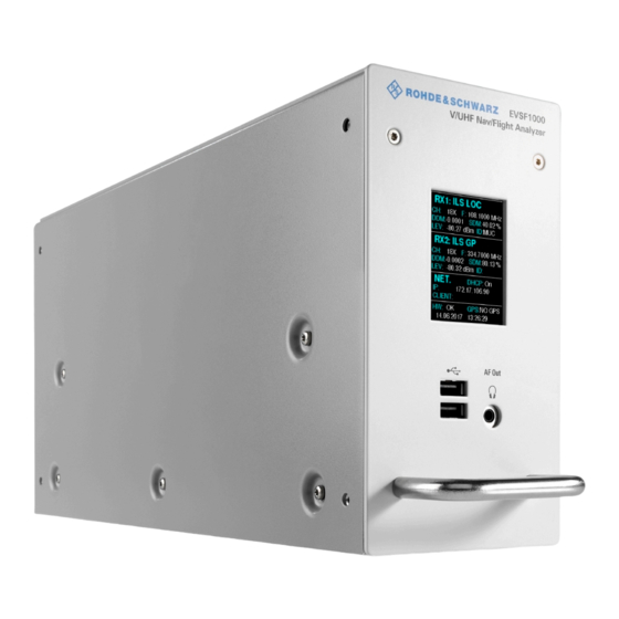
® Instrument tour R&S EVSF1000 Front panel Instrument tour Front panel This chapter describes the front panel, including all function keys and connectors. Figure 5-1: R&S EVSF1000 - Front panel view Getting Started 1178.6404.02 ─ 06... - Page 24 Connector for a headset with a 3.5 mm jack plug. 5.1.4 Carrying handle The carrying handle is used to insert and remove the R&S EVSF1000 from the flight inspection rack. You can also lift and carry the instrument by the handle. Getting Started 1178.6404.02 ─ 06...
- Page 25 Instrument tour R&S EVSF1000 Rear panel Rear panel Figure 5-2: R&S EVSF1000 - Rear panel view (basic model, without R&S EVSF1-B4 option) 1 = Power Supply 2 = RX2 In 3 = LAN 4 = RS-232 GPS 5 = Device ID with serial number and other labels...
- Page 26 See Chapter 5.2.6, "Optional ARINC connector", on page 28. Figure 5-3: R&S EVSF1000 - Rear panel view with ARINC connector (slide-in option R&S EVSF1-B4) For the specification of the following interfaces, see the R&S EVSF1000 data sheet.
-
Page 27: Power Supply
5.2.2 RX1 in / RX2 in The RX input connectors are 50 Ω N connectors. Use the RX inputs to connect a receiving antenna (max. +13 dBm) to the R&S EVSF1000 for RF signal input. 5.2.3 LAN (ethernet) Operate the R&S EVSF1000 remotely using the LAN connection (Fast Ethernet). -
Page 28: Pps In
(see Fig- 5-3). This connector allows you to slide the R&S EVSF1000 out of a flight inspection rack easily without having to disconnect all cables from the instrument individually. - Page 29 ® Instrument tour R&S EVSF1000 Rear panel Table 5-1: Pin assignment of ARINC connector Signal Description Cable type SPEAKER+/ Speaker/Audio out (AF Out) single, AWG 20-24 AUDIO SPEAKER-/ Speaker/Audio GND (AF Out) single, AWG 20-24 AUDIO_GND ADR_SEL_IN IP-Address-Select single, AWG 20-24...
-
Page 30: Lf In
This connector is available with option R&S EVSF1-B4 only. Provides an AF signal or signals with a very low IF (<25 kHz) to the R&S EVSF1000 for further analysis of typical AF parameters. Furthermore, LF input allows for analysis of non-directional beacon (NDB) signals from 190 kHz to 1750 kHz. -
Page 31: Af Out
If this pin is connected to ground, the address configured as "TCP/IP Address 2" is used. 5.2.12 Device ID The unique device identifier is provided as a barcode sticker on the rear panel of the R&S EVSF1000. It consists of the device order number and a serial number. Getting Started 1178.6404.02 ─ 06... - Page 32 Following accessories are available for rack installation: ● Slide-in option (R&S EVSF1-B4) Provides an ARINC connector on the rear panel of the R&S EVSF1000 which can be connected to the rack tray (R&S EVSF1-Z1 with connector). While the tray remains connected to the aircraft permanently, you can remove the R&S EVSF1000 quickly and easily, without having to connect and discon-...
-
Page 33: Operating Basics
EVSF1000 Basic configuration and status display Operating basics The R&S EVSF1000 is designed for flight inspection and is thus optimized for remote operation, via predefined commands. It does not have a graphical user interface for manual interaction. Nevertheless, the instrument can also be controlled manually, by simulating a user interface on a remotely connected device, and using a connected keyboard. - Page 34 To operate the R&S EVSF1000 from a remote device, you require connection information. By default, the R&S EVSF1000 is set to use the static IP address 10.255.255.98. The assigned IP address and DHCP state of the R&S EVSF1000 is provided in the mini display on the front panel.
- Page 35 Using a VNC viewer application, you simply connect to the instrument, defined by its IP address. The display of the R&S EVSF1000 is shown on the control PC. The keys and other graphical user interface elements are operated using associ- ated keyboard shortcuts on the connected keyboard.
- Page 36 Operating basics R&S EVSF1000 Manual operation from a VNC viewer Figure 6-2: R&S EVSF1000 - GUI overview 1 = Measurement settings area (numeric modes only) 2 = Measurement result area 3 = Softkeys to edit settings and activate functions 4 = Status bar...
- Page 37 "1/2" and "2/2" beneath the softkeys in the display. To switch between the two menus of softkey functions, press the "More softkeys" key beneath the softkeys on the front panel of the R&S EVSF1000. Softkeys can perform a function directly, or open a dialog or submenu with further settings and functions.
- Page 38 ® Operating basics R&S EVSF1000 Manual operation from a VNC viewer Keyboard Usage Display Help Setup Mode Undo Redo PAGE UP Field right PAGE DOWN Field left Screenshot Meas Config Softkey 1 Softkey 2 Softkey 3 Softkey 4 Softkey 5...
- Page 39 Marker 6.3.3 Changing settings and activating functions All functions available on the R&S EVSF1000 can be accessed using the keys on the external keyboard. Some keys provide a softkey menu on the display with fur- ther functions and settings. 1. Select a key as described in...
- Page 40 ® Operating basics R&S EVSF1000 Manual operation from a VNC viewer 2. Select the key for the setting or function as required. If necessary, select [F8] to switch to the second softkey menu. The function is activated, or a new window is displayed to view or change spe- cific settings.
- Page 41 ® Operating basics R&S EVSF1000 Manual operation from a VNC viewer All characters available via this key are displayed. 2. To choose another value provided by this key, press the key again, until your desired value is displayed. 3. With every key stroke, the next possible value of this key is displayed. If all possible values have been displayed, the series starts with the first value again.
- Page 42 34. Remote control is performed using predefined remote commands which are sent from the control device to the R&S EVSF1000. The R&S EVSF1000 can also return queried data to the control device. While in remote control, the R&S EVSF1000 display indicates "Remote" in the status bar.
-
Page 43: Contacting Customer Support
® Contacting customer support R&S EVSF1000 Contacting customer support Technical support – where and when you need it For quick, expert help with any Rohde & Schwarz product, contact our customer support center. A team of highly qualified engineers provides support and works with you to find a solution to your query on any aspect of the operation, program- ming or applications of Rohde &... -
Page 44: Index
® Index R&S EVSF1000 Index Service manual ..........9 Accessories ..........32 AF Out ............. 24 USB connector ........24 User manual ..........9 Brochures ..........10 VNC Viewer ..........35 Customer support ........43 Data sheets ..........10 Front panel ..........23 Getting started ...........
Need help?
Do you have a question about the EVSF1000 and is the answer not in the manual?
Questions and answers