Table of Contents
Advertisement
Quick Links
Advertisement
Table of Contents

Related Manuals for AIC SB401-VG


Summary of Contents for AIC SB401-VG
- Page 1 SB401-VG Storage Barebone User's Manual UM_SB401-VG_v1.2_081921...
-
Page 2: Table Of Contents
Table of Contents Preface ������������������������������������������������������������������������������������������������ i Safety Instructions ������������������������������������������������������������������������������ ii About This Manual ����������������������������������������������������������������������������� iv Chapter 1� Product Features �������������������������������������������������������������� 1 1.1 Box Contents .................... 1 1.2 Specifications .................... 2 1.3 System Block Diagram ................3 1.4 Features ..................... 4 Chapter 2�... - Page 3 4.1 Navigation Keys ..................46 4.2 BIOS Menu ....................47 4.3 Main ......................48 4.3.1 Main ........................48 4.4 Advanced ....................49 4.4.1 Peripheral Configuration ..................49 4.4.2 Video Configuration ...................49 4.4.3 OEMBoard Function ...................49 4.4.4 SIO AST2500 ...................... 50 4.4.5 Socket Configuration ..................50 4.4.6 ME Configuration ....................56 4.4.7 PCH Configuration .....................57 4.4.8 H2O IPMI Configuration ..................58...
- Page 4 Copyright © 2019 AIC, Inc� All Rights Reserved� This document contains proprietary information about AIC products and is not to be disclosed or used except in accordance with applicable agreements.
- Page 5 Document Release History Release Date Version Update Content Decmeber Released to public. 2019 March SW update. 2020 August RAID update. 2021 System Block Diagram update.
-
Page 6: Preface
Disclaimer AIC shall not be liable for technical or editorial errors or omissions contained herein. The information provided is provided "as is" without warranty of any kind. To the extent permitted by law, neither AIC or its affiliates, subcontractors or suppliers will be liable for incidental, special or consequential damages including downtime cost;... -
Page 7: Safety Instructions
Safety Instructions Before you commence, please attentively read the following important discretions below. All cautions and warnings on the equipment or in the manuals should be circumspectly noted and reviewed. Always ground yourself to prevent static electricity. Always ground yourself to prevent static electricity. 請... - Page 8 • Ensure that the voltage of the power source is within the specification on the label when connecting the equipment to the power outlet. The current load and output power of loads must be within the specification. • This equipment must be firmly connected to reliable grounding before usage. Pay special attention to power supplied other than direct connections, e.g.
-
Page 9: About This Manual
This document pellucidly presents a brief overview of the product design, device installation, and firmware settings for SB401-VG. For the latest version of this user's manual, please refer to the AIC website: https://www.aicipc.com/en/productdetail/50999. -
Page 10: Chapter 1� Product Features
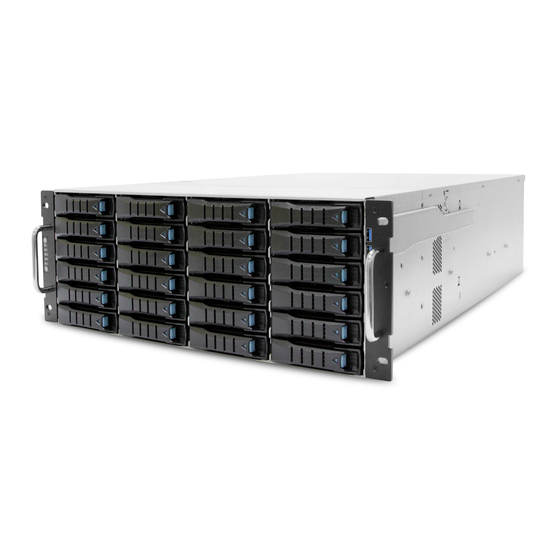
Chapter 1� Product Features SB401-VG is a high density storage server that includes mother board, chassis, power supply, and HDD backplane. For more information about our product, please visit our website at https://www.aicipc.com/en/index. Before removing the subsystem from the shipping carton, visually inspect the physical condition of the shipping carton. -
Page 11: Specifications
Support Expansion Slots PCIe 3.0 • Supports CPU TDP up to 165W • 3 x8 slots (FHHL) (Use over 140W CPU, please contact AIC technical support more info/details about Insyde UEFI BIOS BIOS Type Processor optimized CPUs and specialized system.) •... -
Page 12: System Block Diagram
Chapter 1. Product Features 1�3 System Block Diagram... -
Page 13: Features
Chapter 1. Product Features 1�4 Features SB401-VG is a reliable 4U storage server barebone with 24 hotswap drives bays. This product is designed to accommodate the AIC-patented serverboard, Virgo, which supports two Intel® Xeon® Scalable Processors and 12 DDR4 DIMM to offer greater perfomance, efficiency, and utility for our customers. - Page 14 Chapter 1. Product Features Front Panel 24 x 3.5" hotwap drive tray Item Description Power Button Power Status LED Indicator LAN LED Indicator System Alert LED Indicator System ID LED System ID Button System Reset Button LED Indicator Blue UID activity is detected. No UID activity is detected.
- Page 15 Chapter 1. Product Features Rear Panel Item Description 1200W 1+1 redundant power supply 80+ Platinum 2 x 2.5-inch hot swap drive (15mm) 1 x DB-9 COM port 1 x DB-15 VGA port 1 x GbE RJ45 dedicated to BMC management port 2 x USB 3.0 Type A 2 x 10 GbE SFP+ port...
- Page 16 Chapter 1. Product Features Top View Item Description 1 x Air duct AIC- Virgo Motherboard 3 x 120x25 mm hot swap fans...
-
Page 17: Chapter 2� Hardware Setup
Chapter 2� Hardware Setup This section describes a simple instruction guide for installing the hardware components on the serverboard system. Turn off and unplug all system and peripheral devices before proceeding. 2�1 Central Processing Unit The serverboard supports dual Xeon scalable processors and Socket P0 (LGA-3647). 2�1�1 Processor Installation To ensure a safe and easy setup, you need to prepare before installation: ... - Page 18 Chapter 2. Hardware Setup Processor Socker Assembly: The server board includes two processor sockets (LGA-3647), supports two Intel® Xeon® Processor Scalable Family and has a Thermal Design Power (TDP) of up to 165W on selected models. PHM (Processor Heat sink Module) Component: Non Frabic Processor Non Frabic...
- Page 19 Chapter 2. Hardware Setup PHM Screw Installation Order: The PHM sits level with the processor socket assembly. The PHM is NOT installed properly if it does not sit level with the processor socket assembly. Once the PHM is seated over the processor socket assembly, the four heat sink torque screws must be secured in the following order as shown below.
-
Page 20: Air Duct
Chapter 2. Hardware Setup 2�1�2 Air Duct Position the air duct on top of the heatsink and secure the screw. Ensure that the air duct is accurately aligned. Air duct location (Top view) CAUTION Avoid moving the heat sink after it has contacted the top of the CPU. Too much movement could disturb the layer of thermal compound, causing voids, and leading to ineffective heat dissipation and component damage. -
Page 21: System Memory
Chapter 2. Hardware Setup 2�2 System Memory This server board supports up to twelve DDR4 2400 and 2666 Registered ECC DRAM/ Load-Reduced DIMM. JDIMML0 JDIMML0 JDIMML0 JDIMMK0 JDIMMK0 JDIMMK0 JDIMMJ0 JDIMMJ0 JDIMMJ0 JDIMMC0 JDIMMC0 JDIMMC0 JDIMMB0 JDIMMB0 JDIMMB0 JDIMMA0 JDIMMA0 JDIMMA0 CPU 1 CPU 1... -
Page 22: Dimm Installation Order
Chapter 2. Hardware Setup 2�2�1 DIMM Installation Order JDIMML0 JDIMMC0 JDIMMK0 JDIMMB0 JDIMMJ0 JDIMMA0 DIMM Numbers DIMM ARRANGMENT CPU 0 CPU 0 CPU 0 CPU 1 CPU 1 CPU 1 CPU1 CPU0 2 DIMMs JDIMM_L0 JDIMM_C0 JDIMMG0 JDIMMD0 JDIMMH0 JDIMME0 JDIMMI0 JDIMMF0 JDIMML0... - Page 23 Chapter 2. Hardware Setup JDIMML0 JDIMMC0 JDIMMK0 JDIMMB0 JDIMMJ0 JDIMMA0 CPU1 CPU0 JDIMM_L0 JDIMM_C0 CPU 0 CPU 0 CPU 0 CPU 1 CPU 1 CPU 1 JDIMM_K0 JDIMM_B0 10 DIMMs JDIMM_J0 JDIMM_A0 JDIMM_G0 JDIMM_D0 JDIMMG0 JDIMMD0 JDIMM_I0 JDIMM_F0 JDIMMH0 JDIMME0 JDIMMI0 JDIMMF0 JDIMML0...
-
Page 24: Dcpmm Dimm Population
Chapter 2. Hardware Setup 2�2�2 DCPMM DIMM Population CPU0 CPU1 DIMM JDIMMF0 JDIMME0 JDIMMD0 JDIMMA0 JDIMMB0 JDIMMC0 JDIMML0 JDIMMK0 JDIMMJ0 JDIMMG0 JDIMMH0 JDIMMI0 Direct DCPMM DRAM1 DRAM1 DRAM1 DRAM1 DCPMM Mode Memory DCPMM DRAM2 DRAM2 DRAM2 DRAM2 DCPMM Mode Mixed Memory DCPMM DRAM3... -
Page 25: Dimm Installation
Chapter 2. Hardware Setup 2�2�3 DIMM Installation Step 1 Unlock the DIMM socket by pressing the retaining clips outward. Step 2 Insert the memory module into the slot. Make sure that the DIMM notch is accurately positioned. DIMM notch Step 3 Close the retaining clips to complete installation. This information is provided for professional technicians only. -
Page 26: Top Cover
Chapter 2. Hardware Setup 2�3 Top Cover Press the release buttons on both sides of the chassis to release the top cover. Slide the top cover towards the rear end of the system barebone. Lift the cover upward to remove. Push Press This information is provided for professional technicians only. -
Page 27: Power Supply Unit
Chapter 2. Hardware Setup 2�4 Power Supply Unit 2�4�1 Replacing the Power Supply Unit Press the ejector to release the power supply unit. Pull the handle to remove the module out of the chassis. Push the new power supply unit into the chassis. Ensure that the module is robustly hooked into the cage. -
Page 28: Fan
Chapter 2. Hardware Setup 2�5 Fan Initiate the removal of the fan by unplugging the cables and connectors from the fan. Extract the fan by carefully dislodging the rubber connectors on the fan from the securing bracket. Insert the new fan into the chassis by verifying the alignment of the rubber connectors and bracket. -
Page 29: Hard Disk Drive
Chapter 2. Hardware Setup 2�6 Hard Disk Drive 2�6�1 Hard Disk Drive: 3�5-inch Press the release button the tray lever to loosen the lever. Pull the tray lever outward completely. Pull the tray out of the system. Pull Open Press... -
Page 30: Hard Disk Drive: 2.5-Inch
Chapter 2. Hardware Setup 2�6�2 Hard Disk Drive: 2�5-inch Press the release button the tray lever to loosen the lever. Pull the tray lever outward completely. Pull the tray out of the system. Open Press Pull Insert the hard disk drive into the tray. Ensure that the dimples on the tray match the hard disk drive. -
Page 31: Led
Chapter 2. Hardware Setup 2�6�3 LED Color Item Behavior Description Blue HDD is present. HDD activity is detected or have located HDD Blue Blinking HDD Activity (slow). HDD is not connected or the system power is Off. No control bit is set or set by any of the following bits: 1. -
Page 32: Drive Slot Map
Chapter 2. Hardware Setup 2�6�4 Drive Slot Map HBA card MegaRAID card... -
Page 33: Slide Rail
Chapter 2. Hardware Setup 2�7 Slide Rail NOTE This sections provides a basic instruction for mounting the slide rail onto the system. Tool-less rails vary per order. The rail in this manual may not exactly match the rail for your system. Please refer to the spefications or quick installation guide that came with your purchased product. - Page 34 Chapter 2. Hardware Setup Install the inner rail onto the system barebone. Lock the keyholes and secure the screws. Keyhole screw Continue installing the outer rail bracket to the mounting frame. Attach the outer rail assembling to the frame and press the bracket to fix the rail onto the frame. Repeat to fully mount the bracket assembly.
- Page 35 Chapter 2. Hardware Setup Pull out the middle channel until the ball bearing retainer is locked forward. CAUTION Verify ball bearing retainer is locked forward. Slide the release tab and push barebone into rack. Make sure the barebone is completely installed onto the rack.
-
Page 36: Chapter 3� Hardware Settings
Chapter 3� Hardware Settings This section describes the jumpers, internal connectors and internal LEDs settings. 3�1 Motherboard 3�1�1 Block Diagram Platform Environment Control Interface(PECI) DIMM #H0 DIMM #J0 DIMM #L0 DIMM #B0 DIMM #D0 DIMM #F0 DIMM #G0 DIMM #I0 DIMM #K0 DIMM #A0 DIMM #C0... -
Page 37: Content List
Chapter 3. Hardware Settings 3�1�2 Content List Connector/Jumper/Header Location Connector/Jumper/Header Location Power Supply JPWR1, JPWR3, Front I/O USB Header JUSB_INT Connector JPWR4 Power Supply JPWR2 SSI Front Panel Header JFRNT_SSI Connector External Thermal J2, J13, J24 NGFF Connector JNGFF Sensor CPU Fan Header J1 &... -
Page 38: Placement
Chapter 3. Hardware Settings 3�1�3 Placement CPU1 CPU1 CPU0 CPU0 33 31 27 26 41 40 39 38b 3a 35b 35a 30 29 25b 25a... -
Page 39: Connector
Chapter 3. Hardware Settings 3�1�4 Connector 1a ~ 1c Power Connector (JPWR1, JPWR3 & JPWR4) GND 1 5 +12V GND 2 6 +12V GND 3 7 +12V GND 4 8 +12V 2 Power Connector (JPWR2) +3.3V 1 13 +3.3V +3.3V 2 14 +12V GND 3 15 GND... - Page 40 Chapter 3. Hardware Settings 8 PMBus Header (JPMBUS) 1 SMB_PMBUS_CLK 2 SMB_PMBUS_DATA 3 PMBUS_ALERT_N 4 GND 5 +3.3V 9 SAS IOC UART Header (J20) 1 UART0_TX 2 GND 3 UART0_RX 4 SAS3008_1V8 15 PCH SSGPIO Header (JSSGPIO) GND 1 2 PCH_SSDATAOUT0 PCH_SSDATAOUT1 3 4 PCH_SSLOAD +3.3V 5...
- Page 41 Chapter 3. Hardware Settings 28 SSI Front Panel Header (JFRNT_SSI) +3.3V 1 2 +3.3V_DUAL KEY (no pin) 3 4 +5V_AUX PWR_LED# 5 6 UIDLED_OUT# +3.3V 7 8 SYS_HEALTH#2 HD_LED# 9 10 SYS_HEALTH#1 SW_PWR_BTN# 11 12 LAN1_LINK_UP GND 13 14 LAN1_TRAFFIC SW_RST_BTN# 15 16 I2C8SDA GND 17 18 I2C8SCL UID_SW_IN# 19 20 INTRUDER#...
- Page 42 Chapter 3. Hardware Settings 39 VROC KEY Header (JRAID_KEY) 1 GND 2 +3.3V_DUAL 3 GND 4 PCH_GPP_C10 40 LCM Header (JLCM) 1 SW_PWR_BTN# 2 SW_RST_BTN# 3 TXDC 4 RXDC 5 GND 41 10GbE Carrier Board Header (J28) +3.3V_DUAL 1 2 +3.3V_DUAL LAN_LED3_ACT 3 4 LAN_LED2_ACT LAN_LED3_10G 5...
-
Page 43: Jumper
Chapter 3. Hardware Settings 51 Front VGA Header (VGA_INT) DVO_5V 1 2 GND GND 3 4 DACROA DDC_DATAO 5 6 GND AVSYNCO 7 8 DACGOA AHSYNCO 9 10 GND DDC_CLKO 11 12 DACBOA Power Connector (JPWR5) GND 1 3 +12V GND 2 4 +12V 3�1�5 Jumper... - Page 44 Chapter 3. Hardware Settings 19 Flash Descriptor Security override Jumper (J8) Setting Short Flash Security override Open Normal Default 20 NTB Jumper (JNTB) JNTB Setting Short Downstream port Open Upstream port Default 22 System Power Good Lock (JPG_LOCK) JPG_LOCK Setting Short Lock Open...
-
Page 45: Internal Led
Chapter 3. Hardware Settings 3�1�6 Internal LED LAN2 10G LED LAN1 10G LED SFP+ LAN1 1G LED LAN2 1G LED LAN4 1G/10G LED LAN3 1G/10G LED BMC Heart Beat LED SAS IOC Status LED NVME Hot-Plug LED (PHY0~PHY7) SAS IOC Heart Beat LED NGFF SAS IOC Error LED System PG LED... -
Page 46: Rear I/O Panel
Chapter 3. Hardware Settings 3�1�7 Rear I/O Panel Item Placement Item Placement COM port RJ45 port for BMC VGA port USB 2.0/3.0 Port *2 LAN LED Activity/Link Speed Item Color Behavior No link. Activity/Link LED Yellow (blinking) Data activity. Link. -
Page 47: Hdd Backplane: 2 Bay
Chapter 3. Hardware Settings 3�2 HDD Backplane: 2 Bay 3�2�1 Connector Location Top view HDD1 HDD2 Backside view SATA Connector SATA Connector SATA Connector SATA Connector... -
Page 48: Connector
Chapter 3. Hardware Settings 3�2�2 Connector Power connector (JP1) LED I/O Connector Description Description LED signal From External Fail LED- Fail LED0- output input control ACC LED0- ACC LED0-... -
Page 49: Hdd Backplane: 24 Bay
Chapter 3. Hardware Settings 3�3 HDD Backplane: 24 Bay 3�3�1 Placement Top view Backside view... -
Page 50: Connector Location
Chapter 3. Hardware Settings 3�3�2 Connector Location JFAN1 JMCU_UART JFAN4 JI2C4 JEXP_UART JPMBUS JI2C0 JFAN3 JI2C3 JEXP2 JMCU_DBG JFAN2 SASHD3 SASHD2 SASHD1 JPWR1 JPWR2 JFRONT 3�3�3 Connectors Power Connector (JPWR1) Description Description +12V +12V +3.3V MUTE_L +5VSTBY PSU_N1 PS_ON_L Power Connector (JPWR2) Description Description +12V... - Page 51 Chapter 3. Hardware Settings PMBUS Connector (JPMBUS) Description PMBUS_CLOCK PMBUS_DATA C Connector (JI2C0, JI2C3, JI2C4) Description I2C_CLOCK I2C_DATA Fan Connector (JFAN1, JFAN2, JFAN3, JFAN4) Description +12V TACH Console for Expander (JEXP_UART) Description Description DEBUG_RXD SMART_RXD DEBUG_TXD SMART_TXD...
- Page 52 Chapter 3. Hardware Settings Remote Power Control (JMCU_UART) Description Description DOWN_RXD UP_RXD DOWN_TXD UP_TXD Console for MCU (JMCU_DBG) Description MCU_RXD MCU_TXD 2.54mm Header for Front I/O (JFRONT) Fan number select • Fan number select Pin [5,6] Pin [3,4] Pin [1,2] Fan no�...
-
Page 53: Jumper
Chapter 3. Hardware Settings 3�3�4 Jumper Backside view JMD_SEL JMCU_RST Open Normal, default JMCU_RST Close Reset MCU Open Normal, default JMD_SEL Close Boot loader mode 3�3�5 Internal LED Backside view LED2 LED1 SASHD Status LED LED3 Blue Link up SAS HD Link Status Blue Blinking Activity detected... -
Page 54: Cable Routing
Chapter 3. Hardware Settings 3�3�6 Cable Routing Top view Connects to SATA/SAS storage device Connects to SATA/SAS storage device Bottom view Connects motherboard to power source. -
Page 55: Chapter 4� Bios Configuration Settings
BIOS update. The BIOS menu provided are the most updated ones when this manual is written. NOTE For further details about the BIOS, please refer to BIOS section in the Virgo manual for reference. AIC® website link: https://www.aicipc.com/en/productdetail/20855. 4�1 Navigation Keys The navigation keys are listed below. Function Key Description <... -
Page 56: Bios Menu
Chapter 4. BIOS Configuration Settings 4�2 BIOS Menu Press and to select the options of the menu bar. Press Enter to access the option screen. Menu Description Main Displays basic system information and date & time. Advanced Allows configuration of advanced system settings. Security Sets passwords and security functions. -
Page 57: Main
Chapter 4. BIOS Configuration Settings 4�3 Main 4�3�1 Main Main System time Configures the current time. System date Configures the current date. -
Page 58: Advanced
Chapter 4. BIOS Configuration Settings 4�4 Advanced 4.4.1 Peripheral Configuration Peripheral Configuration PCIe SR-IOV Enable Disable PCIe ARI Enable Disable ARI Forward Enable Disable Spread Spectrum Enable Disable 4.4.2 Video Configuration Video Configuration Display Mode Plug In First On Board First 4�4�3 OEMBoard Function OEMBoard Function SMBIOS Updated... -
Page 59: Sio Ast2500
Chapter 4. BIOS Configuration Settings 4�4�4 SIO AST2500 SIO AST2500 Serial Port A Auto Enable Disable Base I/O Address Interrupt IRQ3 IRQ4 Serial Port B Auto Enable Disable Base I/O Address Interrupt IRQ3 IRQ4 Serial Port D Auto Enable Disable Base I/O Address Interrupt IRQ7... - Page 60 Chapter 4. BIOS Configuration Settings Volatile Memory Auto Mode AppDirect cache Auto Enable Disable eADR Support Auto Enable Disable 1LM Memory 256B Target, 64B Target, 64B Interleave Auto 256B Channel Channel Granularity Memory Map IMC Interleaving Auto 1-way Interleave 2-way Interleave Channel Auto 1-way Interleave...
- Page 61 Chapter 4. BIOS Configuration Settings App Direct Enable Disable Memory Hole SWSMI implementation SMBus Max Min= 0, Max= 4294967295 Access Time NGNVM DIMM NGN Configuration Secure Erase SMBus Release Min= 0, Max= 4294967295 Unit Delay Erase All DIMMs Enable Disable S0 CH0~5 S1 CH0~5 Enable...
- Page 62 Chapter 4. BIOS Configuration Settings PCI 64-Bit Resource Enable Disable Allocation PCIe Train by BIOS PCIe Hot Plug Auto Manual Enable Disable PCIe ACPI Hot Plug Enable Disable Per-Port PCI-E Completion Timeout (Global) Per-Port Disable 50us to 10ms 16ms to 55ms 65ms to 210ms 260ms to PCI-E Global Timeout Value...
- Page 63 Chapter 4. BIOS Configuration Settings Intel® VMD 32-bit non-prefetchable for Volume 64-bit non-prefetchable Intel® VMD MemBar2 IIO Configuration Management technology attribute Device on 64-bit prefetchable Socket 0 WFR Uncore GV Auto Enable Disable Rate Reduction Uncore Freq Enable Disable Scaling (UFS) 128 Heavy 256 Light 256 Heavy...
- Page 64 Chapter 4. BIOS Configuration Settings Non-Snoop Enable Disable Latency Override Latency Non-Snoop Tolerence Latency Min=0, Max=7 Requirement Multiplier Non-Snoop Min=0x0, Max=0x3ff Latency Value IIO0_PKGC_ Enable CLK_GATE_ Disable DISABLE IIO1_PKGC_ Enable CLK_GATE_ Disable DISABLE IIO2_PKGC_ Enable CLK_GATE_ Disable DISABLE UPI01_PKGC_ Enable CLK_GATE_ Disable DISABLE...
-
Page 65: 4.4.6 Me Configuration
Chapter 4. BIOS Configuration Settings 4.4.6 ME Configuration ME Configuration Altitude Min=0x0, Max=0xffff Server ME General ME Configuration Configuration MCTP Bus Owner Min=0x0, Max=0xffff ME Initialization Min=0, Max=12 Complete Timeout Enable HSIO Enable Disable Messaging DRAM Init Done None Enable Auto - true status 0 - Success DRAM Initialization... -
Page 66: 4.4.7 Pch Configuration
Chapter 4. BIOS Configuration Settings 4.4.7 PCH Configuration PCH Configuration PCH Devices PCH state after G3 Last State SATA Controller Enable Disable Configure SATA as AHCI RAID Support Aggressive Link Power Enable Disable Management Port 0~7 Enable Disable SATA Port 0 DevSlp Enable Disable PCH SATA... -
Page 67: 4.4.8 H2O Ipmi Configuration
Chapter 4. BIOS Configuration Settings 4.4.8 H2O IPMI Configuration H2O IPMI Configuration IPMI Support Enable Disable BMC Warmup Time Min=0, Max=240 ACPI SPMI Table Enable Disable Boot Option Support Enable Disable Set BIOS version to Enable Disable Watchdog Timer Support Enable Disable Not disable in OS... -
Page 68: 4.4.11 H2O Event Log Config Manager
Chapter 4. BIOS Configuration Settings 4.4.11 H2O Event Log Config Manager H2O Event Log Config Manager BIOS Log Event To BIOS Event Log BIOS Event BMC SEL Memory Disable Configuration Log Viewer Event Log Overwrite Clear All Stop Logging Full option POST Message Enable Disable... -
Page 69: Security
Chapter 4. BIOS Configuration Settings 4�5 Security 4�5�1 Security Security Current TPM Device Not Detected TPM 1.2 TPM 2.0 TPM Active PCR Hash SHA1, SHA256 Algorithm TPM Hardware Supported Hash SHA1, SHA256 Algorithm TrEE Protocol Version 1.0 TPM Availability Available Hidden TPM Operation No operation... -
Page 70: Power
Chapter 4. BIOS Configuration Settings 4�6 Power 4�6�1 Power Power Wake on PME Enable Disable... -
Page 71: Boot
Chapter 4. BIOS Configuration Settings 4�7 Boot 4�7�1 Boot Boot Boot Type Dual Boot Type Legacy Boot Type UEFI Boot Type Quick Boot Enable Disable Quiet Boot Enable Disable Network Stack Enable Disable Disable UEFI:IPv4 UEFI:IPv6 PXE Boot capability UEFI:IPv4/UEFI:IPv6 Legacy Add Boot Options First... -
Page 72: Exit
Chapter 4. BIOS Configuration Settings 4�8 Exit 4�8�1 Exit Exit Exit Saving Changes Exit system setup and save your changes. Save Change Without Exit Save your changes without exiting the system. Exit Discarding Changes Discard your changes when existing the system. Load Optimal Defaults Load optimal default items. -
Page 73: Chapter 5� Bmc Configuration Settings
Chapter 5� BMC Configuration Settings Chapter 5� BMC Configuration Settings Insert Ethernet LAN cable into the BMC LAN port. There are two methods to setup BMC IP: BMC management port (Dedicated NIC channel 1 ) 2 x 10GbE SFP+ (Shared NIC channel 8) 5�1 Setup Step 1 BIOS SETUP ... - Page 74 Chapter 5. BMC Configuration Settings...
- Page 75 Chapter 5. BMC Configuration Settings Step 3 Input the subnet mask address.
-
Page 76: Web Gui
Chapter 5. BMC Configuration Settings 5�2 Web GUI The IP address below is an example using the default IP setting. The IP address is configurable. Step 1 Open the browser then type default BMC IP address: 192.168.22.22 Step 2 Use the default user name and password for first-time login to BMC WEB GUI. Field: Default User Name:... - Page 77 Chapter 5. BMC Configuration Settings Dashboard: The Dashboard page gives the overall information about the status of a device. Server Health - Sensor Readings: Then Sensors Readings page displays all the sensor related information. Settings: The Settings page allows you to access various configuration settings.
- Page 78 Chapter 5. BMC Configuration Settings KVM Mouse Setting: The KVM Mouse Setting page displays the setting for mouse emulation from local window to remote screen. • For Windows OS environment, set mode to absolute. • For Linux OS environment, set mode to relative. •...
- Page 79 Chapter 5. BMC Configuration Settings Environmental setting: NOTE For further details about the BMC, please refer to BMC section in the Virgo manual for reference. AIC® website link: https://www.aicipc.com/en/productdetail/20855.
-
Page 80: Chapter 6� Raid Configuration
Chapter 6� RAID Configuration This firmware (LSI® Integrated RAID solution) provides protection for the sytem boot volume. This firmware features 4 fundamental RAID attributes: • The Integrated Mirroring (RAID 1) • The Integrated Mirroring + Striping (RAID 10) • The Integrated Mirroring Enhanced (RAID 1E) •... -
Page 81: Create An Integrated Mirroring Enhanced/Mirroring + Striping Volume
Chapter 6. RAID Configuration Step 2: Select RAID Properties and press Enter. Step 3: Select Create RAID 1 Volume. Step 4: Select a line that has a No entry in the RAID Disk column. , press the space bar to change the to add the disk to the new array. -
Page 82: Expand An Integrated Mirroring Volume With Oce
Chapter 6. RAID Configuration 6�1�4 Expand an Integrated Mirroring Volume with OCE Expand an existing RAID 1 volume with OCE. Procedure Step 1: Replace one of the two volume disk drives with a drive that has at least 50 GB more capacity. -
Page 83: Manage Hot Spare Disks
Chapter 6. RAID Configuration 6�2 Manage Hot Spare Disks Create/delete one or two global hot spare disks to safeguard the data on mirrored volumes on the controller. 6�2�1 Create Hot Spare Disks Add global hot spare disks to an existing volume. Procedure Step 1: Select the adapter on which you want to create hot spare disks and press Enter. -
Page 84: Delete A Hot Spare Disk
Chapter 6. RAID Configuration 6�2�2 Delete a Hot Spare Disk Delete a global hot spare disk. Procedure Step 1: Access the Manage Hot Spares window by following the first five steps of Section 1.2.1. Step 2: Select a hot spare disk to delete and press C. Step 3: Select Save changes and then exit this menu to complete the deletion of the hot... -
Page 85: Activate An Array
Chapter 6. RAID Configuration 6�3�3 Activate an Array Activate a selected array. Procedure Step 1: Select an adapter and press Enter. Step 2: Select RAID Properties and then press Enter. Step 3: Select View Existing Array. If necessary, press Alt + N to switch to another array on this adapter. -
Page 86: Select A Boot Disk
Chapter 6. RAID Configuration 6�3�6 Select a Boot Disk Select a boot disk. Procedure Step 1: Select an adapter from the adapter list. Step 2: Select the SAS Topology option. If a device is currently designated as the boot device, the Device Info column on the SAS Topology window lists the word Boot, as shown below. -
Page 87: Integrated Striping
Chapter 6. RAID Configuration 6�4 Integrated Striping Configure Integrated Striping volumes. 6.4.1 Integrated Striping Configiration Procedure Step 1: Load BIOS and press Ctrl+C to initiate SAS3 BIOS CU. Please wait, invoking SAS Configuration Utility... The following message will appear : Step 2: Wait for a few seconds for the Adapter List window to appear. -
Page 88: Other Configuration Tasks
Chapter 6. RAID Configuration 6.4.3 Other Configuration Tasks View Array Properties View the RAID properties of an array. Step 1: Select an adapter from the adapter list. Step 2: Select RAID Properties. Step 3: Select View Existing Array. The View Array window will appear, showing information about the array and each disk in it. - Page 89 Chapter 6. RAID Configuration Locate Disk Drives in a Volume Locate disk drives by flashing their LEDs. Procedure Step 1: Select the controller on the Adapter List window and press Enter. Step 2: Highlight SAS Topology and press Enter. The SAS Topology window will appear. Step 3: Select the disk in the Device Identifier column and press Enter.
-
Page 90: Intel® Rste
Chapter 6. RAID Configuration 6�5 Intel® RSTe Intel® RSTe (Rapid Storage Technology enterprise) is a software that suports systems equipped with SSDs, SATA or SAS devices. The purpose of its utility is to manage and configure RAID systems. Supported features of Intel® RSTe include SATA RAID Option ROM, SCU RAID Legacy Option ROM, SATA/SCU RAID UEFI Driver, Graphical User Interface, CSMI (Common Storage Managemnet Interface), hot plug, SCU and AHCI drive roaming, SGPIO on SCU, hot spare disk, RAID smart support and many other features. -
Page 91: Chapter 7� Technical Support
Boulvard Suite 404 Fremont, CA 94539, United States Tel: +1-510-573-6730 Sales Email: sales@aicipc�com Support Email: support@aicipc�com For additional technical support or questions about trouble shooting, please contact the AIC® representative nearest to you or visit our AIC® website for more information. AIC® website: https://www.aicipc.com/en/faq.
Need help?
Do you have a question about the SB401-VG and is the answer not in the manual?
Questions and answers