Table of Contents
Advertisement
Quick Links
Download this manual
See also:
Instruction Manual
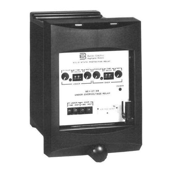
The BE1-27 Undervoltage, BE1-59 Overvoltage and BE1-27/59 Under/
Overvoltage Relays' solid-state design provides a reliable response to
protect power system equipment from adverse voltage conditions.
ADVANTAGES
Pickup continuously adjustable over a wide range.
•
Instantaneous functions offer immediate response to extreme
•
voltage conditions.
Individually adjustable definite, short inverse, medium inverse,
•
or long inverse timing for each time-delayed under/overvoltage
function.
Low sensing and supply burdens.
•
Warranty 5 years.
•
AD DITIONAL INFO R MATION
INSTRUCTION MANUAL
Request Publication 9170600990
STANDARDS, DIMENSIONS and ACCESSORIES
Request Bulletin SDA
§l
Basler Electric
P. 0. BOX 269 HIGHLAND, ILLINOIS 62249, U.S.A. PHONE 618-654-2341
BE1-27, BE1-59
BE1-27/59
VOLTAGE RELAYS
APPLICATION
Page
SPECIFICATIONS
Pages 3 -5
EXTERNAL
CONNECTIONS
Page 6
ORDERING
INFORMATION
Pages
FAX 618-654-2351
2
7
and
8
UBF- 4
3-01
Advertisement
Table of Contents

Related Manuals for Basler BE1-27


Summary of Contents for Basler BE1-27
- Page 1 BE1-27, BE1-59 BE1-27/59 VOLTAGE RELAYS The BE1-27 Undervoltage, BE1-59 Overvoltage and BE1-27/59 Under/ Overvoltage Relays' solid-state design provides a reliable response to protect power system equipment from adverse voltage conditions. ADVANTAGES APPLICATION Page Pickup continuously adjustable over a wide range.
- Page 2 The BE1-27 Undervoltage Relay PURPOSE can initiate switching after a given time delay to avoid The BE1-27 Undervoltage, BE 1-59 Overvoltage and the transfer switching during temporary low voltage condi BE1-27/59 Under/Overvoltage Relays are solid-state tions. To return the substation to normal service upon the...
-
Page 3: Specifications
System Voltages within 2% of 0.5 volt of the setting, whichever is greater. The BE1-27, BE 1-59, and BE1-27/59 relays are available Dropout is within 2% of actual pickup, occurring in 50 with three sensing input ranges. The 55 to 160V range is milliseconds or less. - Page 4 BE1-27, 59, 27/59 continued SPECIFICATIONS, indicator is illuminated and the corresponding time delay only when normally open (NO) output contacts have been circuit is initiated. If the adverse voltage condition is specified. present at the end of the programmed time delay, the...
- Page 5 BE1-27, 59, 27/59 continued SPECIFICATIONS, SHORT INVERSE-UNDER SHORT INVERSE-OVER 10 0 5 .." '" RANGE2 2.5 RANGE2 12 " " " RANGEl 10 RANGEl 48 " " RANGE4 20 RANGE4 96 VOLTAGE DIFFERENCE FROM PICKUP VOLTAGE DIFFERENCE FROM PICKUP...
- Page 6 BE1-27, 59, 27/59 CONNECTIONS BE1-27 BE1-59 BE1-27/59 Figure 3 - Vol tage Sensing 27/59 27/59 '27/59 LEGEND: Under/Overvoltage Relay 27/59 Breaker Aux. Contacts 52 a Breaker Trip Coil 52TC Timed Undervoltage Timed Overvoltage Instantaneous Undervoltage 17 19 15 AUXILIARY CONTACTS...
-
Page 7: Style Number
BE1-27 Style Test Plug DDDDDD DDDDD To allow testing of the relay without removing system BE1-59 Style wiring, order two test plugs, Basler part number 10095. DOD ODD DDDDD BE1-27/59 Style Extender Board The Extender Board will permit troubleshooting of the Complete the Style Number by selecting one feature C. -
Page 8: Style N U M Be R I Dentification C Hart
BE1-27, 59, 27/59 STYLE N U M BE R I DENTIFICATION C HART :����� �, 1- 7 59 MODEL NO. POWER SENSING INPUT OPTION TIM IN G OUTPUT OPTION3 SUPPLY TYPE 27 or 59 27 or 59 27 or A) Single-phase... -
Page 9: Additional Information
• Pages 11 - 1 AD DITIONAL INFO RMATION INSTRUCTION MANUAL Request Publication 91711 00990 STANDARDS, DIMENSIONS, AND ACCESSORIES Request bulletin SDA § .Basler Electric UBU- 5 3-96 P. 0. BOX 269 HIGHLAND, ILLINOIS 62249, U.S.A. PHONE 618·654·2341 FAX 618·654·2351... -
Page 10: Application Examples
BE1-32R, BE1-320/U APPLICATION prime mover. Sustained motoring can cause severe PURPOSE damage to the prime mover. The Directional Power The BE1-32R Directional Overpower Relay and the BE1 - Relay, with its wide sensitivity range, can detect levels of 32 0/U, Directional Over/Underpower Relays sense real reverse real power flow as low as 0.5 Watts secondary power flow (EI cos These relays are solid-state devices... -
Page 11: Example 3 - Generator Overload
"stop" signal when utility power decreased below a selected level. A definite time delay will generally be provided for the "stop" signal of one minute or more. The Basler Model BE1-32 0/U Power � Relay incorporates both over and under power sensing in one relay, which makes it ideal for this application. - Page 12 With the many options and combinations of options goo) Since the sine of Q equals the cosine of (Q available, the Basler Electric Directional Power Relays relay can be connected to measure only reactive power can be adapted to multitude of systems and situations...
-
Page 13: Sensing Input Types
BE1-32R, BE1-320/U continued SPECIFICATIONS, If sensing input range 2, 3, 5, 6, 8 or 9 is selected, the input transformers are capable of 1 0 A continuous (Figure 8) with 30° phase shift. This sensing configuration current, 15 A for 1 minute and 200 A for 1 second. monitors a line-to-line voltage and a single phase current of a three-phase, three-wire circuit and calculates the power Maximum burden for each current input (2 terminals) is 1... -
Page 14: Power Range Pickup
BE1-32R, BE1-320/U continued SPECIFICATIONS, Nominal Input Burden sensing configuration monitors three line-to-neutral volt Type Input Voltage Voltage Range Nominal ages and three phase currents of a three-phase, four-wire 48Vdc 24to 60 Vdc 6.5W circuit and calculates the power flowing in the tripping direction. -
Page 15: Power Supply Status Output
BE1-32R, BE1-32R 0/U S PECIFICATIONS (continued) Switch Positions (in Watts) Sensing Input Nominal Range Type Volts 10.0 12.0 14.0 16.0 18.0 20.0 2. 5 A,8, 2 Hi 1000 12.0 18.0 24.0 30.0 36.0 42.0 48.0 54.0 60.0 10.5 12.0 13.5 15.0 C,D, 2 Hi... - Page 16 BE1-32R, BE1-320/U continued SPECIFICATIONS, TARGETS Magnetically latched, manually reset target indicators are optionally available to indicate that a trip output has energized. Either internally operated or current operated target may be specified. Current operated targets require 0. 2 A in the output trip circuit to actuate, and trip current must not exceed 30 A for 0.2 seconds, 7 A for 2 minutes, and 3 A continuous.
- Page 17 BE1-32R, BE1-320/U CONNECTIONS � � BE1-32 BE1-32 " " GENERATOR B or V TYPE SENSING TYPE SENSING � � BE1-32 BE1-32 " " TYPE SENSING B or V TYPE SENSING with ACB Rotation Figure Sensing Connections (Continued next page)
- Page 18 BE1-32R, BE1-32R 0/U CONNECTIONS {continued) ROLL B AND C PHASES FOR CHANGING ABC TO ACB ROTATION. "' BE1-32 BE1-32 BE1-32 "' "' ..TYPE E SENSING WITH ABC ROTATION TYPE E SENSING WITH ACB ROTATION Figure (continued) - Sensing Connections £...
- Page 19 Complete the Style Number by selecting one feature To allow testing of the relay without removing system from each column of the Style Number Identification wiring, order two test plugs, Basler Electric part number Chart and entering its designation letter or number into 10095.
- Page 20 N.C. type output contacts. (C,D,E) §l Basler Electric ROUTE 143, BOX 269, HIGHLAND, ILLINOIS U.S.A. 62249 P.A.E. Les Pins, 67319 Wasselonne Cedex FRANCE PHONE 618-654-2341 FAX 618-654-2351 PHONE (33-3-88) 87-1010 FAX (33-3-88) 87-0808 http://www. basler.com, info@basler.com Printed U.S.A.
Need help?
Do you have a question about the BE1-27 and is the answer not in the manual?
Questions and answers