
Related Manuals for Basler BE1-79A


Summary of Contents for Basler BE1-79A
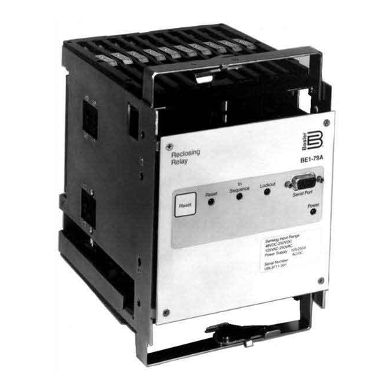
- Page 1 INSTRUCTION MANUAL RECLOSING RELAY BE1-79A Publication: 9310200990 Revision: G 02/08...
- Page 3 NOTE Be sure that the BE1-79A is hard-wired to earth ground with no smaller than 12 AWG copper wire attached to the ground terminal on the rear of the unit case. When the BE1-79A is configured in a system with other devices, it is recommended to use a separate lead to the ground bus from each unit.
- Page 4 February 2008 CONFIDENTIAL INFORMATION of Basler Electric, Highland Illinois, USA. It is loaned for confidential use, subject to return on request, and with the mutual understanding that it will not be used in any manner detrimental to the interest of Basler Electric.
- Page 5 REVISION HISTORY The following information provides a historical summary of the changes made to the BE1-79A hardware, firmware, and software. The corresponding revisions made to this instruction manual (9310200990) are also summarized. Revisions are listed in reverse chronological order. Application Firmware...
- Page 6 Patent information was added to Section 1. Various errors in Sections 1, 3, and 6 were corrected. • A, 09/97 Information pertaining to the power supply holdup feature was added. • —, 01/05 Initial release BE1-79A Introduction 9310200990 Rev G...
-
Page 7: Table Of Contents
SECTION 4 • COMMUNICATION COMMANDS ..................4-1 SECTION 5 • INSTALLATION AND CONFIGURATION ................5-1 SECTION 6 • TESTING ..........................6-1 APPENDIX A • RS CONTACT APPLICATION ..................A-1 APPENDIX B • TERMINAL COMMUNICATION..................B-1 9310200990 Rev G BE1-79A Introduction... - Page 8 This page intentionally left blank. BE1-79A Introduction 9310200990 Rev G...
- Page 9 Power Supply ............................. 1-2 Contact Sensing Inputs ........................1-2 Output Contacts ..........................1-3 Type Tests............................1-3 Environment ............................1-3 Weight ..............................1-3 Patent ..............................1-3 MAINTENANCE ............................. 1-4 Tables Table 1-1. BE1-79A Versions and Features....................1-1 9310200990 Rev G BE1-79A General Information...
- Page 10 This page intentionally left blank. BE1-79A General Information 9310200990 Rev G...
-
Page 11: Section 1 • General Information
GE type S2 case with no wiring changes required. General Electric type ACR11A, ACR11B, ACR11C, ACR11E, and ACR11F reclosing relays can be directly replaced by the BE1-79A-100 or BE1- 79A-101. The BE1-79A-200 is available in a shorter cradle that fits in a Basler S1 case for new installations. -
Page 12: Primary Application
Over 90% of faults occurring on overhead lines may be cleared by momentarily de-energizing the line. Once the circuit breaker has been opened to de-energize the line, the BE1-79A provides a reliable automatic reclosure. The advantages are: •... -
Page 13: Type Tests
Qualified to IEC 68-2-38, 1 Edition 1974, Basic Environmental Test Procedures, Part 2: Test Z/AD: Composite Temperature Humidity Cyclic Test Weight BE1-79A-100, -101: 5 lb (2.3 kg) maximum BE1-79A-200, -201: 13 lb (5.9 kg) maximum Patent Number 6,239,960 9310200990 Rev G BE1-79A General Information... -
Page 14: Maintenance
BE1-79A relays require no preventative maintenance. However, testing should be performed according to scheduled practices. If the relay fails to function properly, contact the Technical Support Services department of Basler Electric for a return authorization number before returning the relay for service. BE1-79A General Information... - Page 15 Figure 2-1. Front Panel Controls and Indicators ..................2-1 Figure 2-2. Style Configuration Switches ....................2-2 Figure 2-3. Instantaneous Reclose Jumper Switch and RS Contact Selection Switch......2-3 Tables Table 2-1. Front Panel Control and Indicator Descriptions ............... 2-1 9310200990 Rev G BE1-79A Controls and Indicators...
- Page 16 This page intentionally left blank. BE1-79A Controls and Indicators 9310200990 Rev G...
-
Page 17: Section 2 • Controls And Indicators
RS-232 Serial Communication Port. A PC or computer terminal running a terminal emulation program such as Windows® HyperTerminal can be connected to this port so that relay settings can be read or changed. Communication with the BE1-79A uses a simple ASCII command language. -
Page 18: Style Configuration Switches
STYLE CONFIGURATION SWITCHES Three switches on the left side of the relay cradle are used to configure the BE1-79A for either ACR11A or ACR11B operation. For simplicity, recloser styles ACR11B, ACR11C, ACR11D, ACR11E, and ACR11F will be referred to as ACR11B throughout this manual. Figure 2-2 illustrates the location of the style configuration switches. -
Page 19: Figure 2-3. Instantaneous Reclose Jumper Switch And Rs Contact Selection Switch
Figure 2-3. Instantaneous Reclose Jumper Switch and RS Contact Selection Switch 9310200990 Rev G BE1-79A Controls and Indicators... - Page 20 This page intentionally left blank. BE1-79A Controls and Indicators 9310200990 Rev G...
-
Page 21: Section 3 • Functional Description
Table 3-2. Contact Sensing Inputs Description for ACR11A Operation............ 3-2 Table 3-3. Contact Sensing Inputs Description for ACR11B Operation............ 3-3 Table 3-4. Outputs Description for ACR11A Operation................3-3 Table 3-5. Outputs Description for ACR11B Operation................3-4 9310200990 Rev G BE1-79A Functional Description... - Page 22 This page intentionally left blank. BE1-79A Functional Description 9310200990 Rev G...
-
Page 23: Section 3 • Functional Description
BE1-79A relays are microprocessor-based devices that provide automatic reclosing of circuit breakers. This section describes the hardware, circuitry, and software of the BE1-79A. HARDWARE The BE1-79A is supplied as an S1 cradle and case (200 series) or an S2 cradle without a case (100 series). 100 Series Description The BE1-79A-100 and –101 consist of a draw-out cradle assembly that is intended for installation in an... -
Page 24: Description
The power supply generates a 24 Vdc output. BE1-79A-101 and BE1-79A-201 relays are equipped with holdup circuitry that maintains relay function for a minimum of 40 cycles after nominal operating power is removed. -
Page 25: Microprocessor
Outputs The BE1-79A has 10 outputs. The function of each output depends on the operating configuration of the relay. Tables 3-4 and 3-5 provide a description of each output for each relay configuration. - Page 26 (GH+E3) 1, 2 Closed only during a reset condition. Opens and stays open when a reclose timing begins or is running. (E4) BE1-79A Functional Description 9310200990 Rev G...
-
Page 27: Interconnections
RS contact configuration switch in the BE1-79A relay. The state of all relay output contacts is shown with all power removed from the relay. Figure 3-2 shows the relay configured for an ACR11A application. Figure 3-3 shows the relay configured for an ACR11B application with an instantaneous recloser jumper. - Page 28 D2633-05 07-26-05 RS mode electronic selector switch (SP-79ARS command) Case-mounted, paddle-operated shorting bars Power Supply Figure 3-3. Relay Interconnections for ACR11B Applications BE1-79A Functional Description 9310200990 Rev G...
-
Page 29: Recloser Operation
Down State Of Relay Timing To Lockout Lockout Time Reached Resetting Reset Timer Expired Lockout Reclose Time Reached Manual Reclose Reset Reclose Attempts Time Reached Done? Reset D2588-06 05-06-97 Reclose Figure 3-4. Power-Up Flow Chart 9310200990 Rev G BE1-79A Functional Description... -
Page 30: Reset
BE1-79 and BE1-79M are based on the breaker opening that immediately precedes each reclose and reset setting. This is not the case with the BE1-79A. Each reclose and reset timer setting begins at time zero when the breaker opens the first time and initiates the first reclose timer. Typically, this makes the first reclose setting the shortest time setting and the fourth reclose setting the longest time setting. - Page 31 Figure 3-5. Reclose Settings Example 9310200990 Rev G BE1-79A Functional Description...
- Page 32 Rec 2 Perform Lockout Perform Lockout Lockout Time? Reset Rec 2 Time? Lockout Reset Complete? Rec 4 Lockout Issue Reclose Perform Signal Lockout Final Reset Time? Reclose Complete? Reset Figure 3-6. Reclosing Flow Chart 3-10 BE1-79A Functional Description 9310200990 Rev G...
-
Page 33: Section 4 • Communication Commands
COMMUNICATION PORT PARAMETERS................... 4-1 ASCII command format.......................... 4-1 Command Format ..........................4-1 Command Response Format ......................4-1 COMMAND DESCRIPTIONS ........................ 4-2 Changing Settings through the Serial Port..................4-2 Tables Table 4-1. Internal Default Settings ......................4-4 9310200990 Rev G BE1-79A Communication Commands... - Page 34 This page intentionally left blank. BE1-79A Communication Commands 9310200990 Rev G...
- Page 35 “>” is returned for a valid command, “?” is returned for an invalid command. Commands received by the BE1-79A consist of two types: requests for information and changes to operating parameters. Commands to change parameters are identified by and equal sign (=). The operating parameters to the right of the equal sign are intended to replace the current operating parameters related to the command.
- Page 36 S could be used to read all reclose settings. COMMAND DESCRIPTIONS BE1-79A command descriptions and examples are provided in the following paragraphs. Changing Settings through the Serial Port The ACCESS command is used to access write privileges while changing relay settings. Relay control functions are disabled when access is granted.
- Page 37 A reset time delay setting less than the reclose time setting will cause an immediate reset following the reclose attempt. SP-79A command example: Read the second reclose and reset timer settings. SP-79A2 15.0,20.0 > 9310200990 Rev G BE1-79A Communication Commands...
- Page 38 Relay Information Command RG-VER Command Purpose: Read information about relay hardware/firmware configuration Syntax: RG-VER Comments: Transmitting the RG-VER command will cause the relay to respond with the relay model number and the firmware version and date. BE1-79A Communication Commands 9310200990 Rev G...
-
Page 39: Section 5 • Installation And Configuration
Figure 5-5. Typical Connections for ACR11B Application................. 5-6 Figure 5-6. Contact Sensing Jumpers....................... 5-7 Figure 5-7. Contact Sensing Jumper Locations ..................5-7 Figure 5-8. PC to BE1-79A Connections....................5-10 Tables Table 5-1. RS-232 Pin Functions ......................5-9 9310200990 Rev G... - Page 40 This page intentionally left blank. BE1-79A Installation and Configuration 9310200990 Rev G...
-
Page 41: Section 5 • Installation And Configuration
Because the BE1-79A is of solid-state design, it does not have to be mounted vertically. Any convenient mounting angle may be chosen. The BE1-79A is available in an S2 cradle or an S1 cradle with case. The S2 cradle is intended for installation in an existing S2 case. Overall dimensions for the S1 case are shown in Figure 5-1. -
Page 42: Rs Switch
RS switch S5 is used to control the RS contact for normally open or normally closed contact configuration. Figure 2-2 and 2-3 should be consulted for the location and setting positions of the style and configuration switches. Figure 5-1. Overall Dimensions, S1 Case BE1-79A Installation and Configuration 9310200990 Rev G... - Page 43 Figure 5-2. Panel Cutout Dimensions, S1 Case 9310200990 Rev G BE1-79A Installation and Configuration...
- Page 44 D2588-17 06-05-97 Figure 5-3. Terminal Connections, Rear View, S1 Case BE1-79A Installation and Configuration 9310200990 Rev G...
- Page 45 Figure 5-4. Typical Connections for ACR11A Application 9310200990 Rev G BE1-79A Installation and Configuration...
- Page 46 Figure 5-5. Typical Connections for ACR11B Application BE1-79A Installation and Configuration 9310200990 Rev G...
-
Page 47: Motor Voltage
No adjustment is required for the motor voltage applied at terminals 5 and 6. The applied voltage can range from 120 to 240 Vac or 125 to 250 Vdc. These terminals serve as the input to the BE1-79A power supply and control functions. -
Page 48: Timing Cams
300 milliseconds (18 cycles) for transmission voltages (including breaker- operating time). The inherent delay of the BE1-79A relay is 22 to 48 milliseconds when set at a time delay of zero. The reclose timers may be adjusted in increments of 0.1 seconds, which is 6 cycles on a 60-hertz system. -
Page 49: Reset Switch
1. Adjust Style Configuration Switches S1, S2, and S3 and Instantaneous Reclose Jumper Switch S4 to the correct positions for your application. 2. Insert the BE1-79A relay and close the cradle latches to lock the relay into the case. 3. Install the connection plugs. -
Page 50: Communication Settings
Communication settings are the formal set of conventions controlling the format and relative timing of message exchange between two communication terminals. The BE1-79A settings are fixed at 9600, 8N1, where 9600 is the baud rate, 8 is the number of data bits, N is the parity (none), and 1 indicates one stop bit. -
Page 51: Section 6 • Testing
Figures Figure 6-1. Test Connections for ACR11A Style Relays................6-3 Figure 6-2. Test Connections for ACR11B Style Relays................6-4 Tables Table 6-1. Instantaneous Reclose Testing Commands ................6-1 Table 6-2. Delayed Reclose Testing Commands..................6-2 9310200990 Rev G BE1-79A Testing... - Page 52 This page intentionally left blank. BE1-79A Testing 9310200990 Rev G...
-
Page 53: Section 6 • Testing
SECTION 6 • TESTING INTRODUCTION You may prefer to test your relay before installation. To test BE1-79A relay functionality, perform the procedures in the following paragraphs. Figure 6-1 illustrates the necessary connections for testing relays configured for ACR11A style operation. The connections diagram for testing relays configured for ACR11B operation is provided in Figure 6-2. -
Page 54: Delayed Reclose Testing
6. Place Test switch S1 in the 52b position before 20 seconds elapse and verify that after 30 seconds, Reclose indicator L2 lights for three seconds. 7. Place Test switch S1 in the 52a position and verify that after 40 seconds, the front panel Reset LED and Reset indicator L1 light. BE1-79A Testing 9310200990 Rev G... - Page 55 Auxiliary Contact - Closed in Reset External Jumpers RS Contact - Closes, opens at time set by user Delayed First Reclose Contact closes when terminal 7 is energized Instantaneous First Reclose Figure 6-1. Test Connections for ACR11A Style Relays 9310200990 Rev G BE1-79A Testing...
- Page 56 GE XLA test plugs.) Reset D2588-09 08-01-05 Auxiliary Contact - Closed in Reset RS Contact - Closes, opens at time set by user Optional Reclose Output Figure 6-2. Test Connections for ACR11B Style Relays BE1-79A Testing 9310200990 Rev G...
-
Page 57: Power Holdup Circuit
RS contacts (terminals 9 and 10) close. The time should be 1.3 seconds or greater. TROUBLESHOOTING TIPS The front panel LED indicators will annunciate certain conditions that will inhibit the BE1-79A relay from providing reclose protection. Blinking LEDs This annunciation indicates low or incorrect relay input voltage. - Page 58 This page intentionally left blank. BE1-79A Testing 9310200990 Rev G...
- Page 59 RS CONTACT EXAMPLE FOR TRANSFORMER LTC BLOCKING ............A-4 SP-79ARS Mode Selection ........................A-4 SP-79ARS Remove Time Selection....................A-4 RS Contact Example for Blocking Instantaneous Overcurrent Tripping ..........A-4 Figures Figure A-1. RS Contact Setting Examples ....................A-3 Tables Table A-1. RS Contact Operation Table....................A-1 9310200990 Rev G BE1-79A RS Contact Application...
- Page 60 This page intentionally left blank. BE1-79A RS Contact Application 9310200990 Rev G...
-
Page 61: Appendix A • Rs Contact Application
APPENDIX A • RS CONTACT APPLICATION INTRODUCTION The functionality of the RS contact in the BE1-79A relay emulates that of an ACR reclosing relay. The RS contact can be applied to disable the instantaneous trip circuit of protection relays after any close attempt, typically leaving only time overcurrent protection in service. -
Page 62: Rs Contact Settings
2.5 seconds after the circuit breaker 52b contact closes for the first trip-out and then be open until the 145 second time is reached or reset occurs. If the BE1-79A goes to reset before the Remove time is reached, the RS contact changes back to its state at reset without having to time to the Remove time setpoint. - Page 63 Figure A-1. RS Contact Setting Examples 9310200990 Rev G BE1-79A RS Contact Application...
-
Page 64: Rs Contact Example For Transformer Ltc Blocking
RS contact to its original NC position and restore the 50 element tripping for the next fault occurrence and trip-close sequence of the circuit breaker. If the 50 element is to remain blocked when the BE1-79A is in lockout, then the RS contact Remove time should be set for 65 seconds also (SP-79ARS=D,5,65). - Page 65 Figure B-1. Connection Description Dialog Box ..................B-1 Figure B-2. Connect To Dialog Box......................B-2 Figure B-3. COM Properties Dialog Box ....................B-2 Figure B-4. Properties, Settings Tab ......................B-3 Figure B-5. ASCII Setup Dialog Box ......................B-4 Tables Table C-1. RS-232 Communication Ports ....................B-4 9310200990 Rev G BE1-79A Terminal Communication...
- Page 66 This page intentionally left blank. BE1-79A Terminal Communication 9310200990 Rev G...
-
Page 67: Appendix B • Terminal Communication
® HyperTerminal (provided with Windows 2000/XP) or other stand-alone software can be used to communicate with a BE1-79A relay. The following instructions are used for configuring HyperTerminal in ® Windows 2000/XP to communicate with your BE1-79A relay. The configuration of other stand-alone software is similar. - Page 68 Click “OK”. This creates an icon with the file name entered in Step 4 and places it in the HyperTerminal folder. Future communication sessions can then be started by clicking the appropriate icon. Figure B-3. COM Properties Dialog Box BE1-79A Terminal Communication 9310200990 Rev G...
- Page 69 Disable Force incoming… by leaving the box unchecked. Place a check at Wrap lines… Click “OK”. Click “OK”. Step 8: Click File and click Save. NOTE Settings changes do not become active until the settings are saved. 9310200990 Rev G BE1-79A Terminal Communication...
- Page 70 VISTA ® HyperTerminal is not provided with Windows Vista. Stand-alone software from other vendors can be used to communicate with a BE1-79A relay. The configuration of stand-alone software is similar to that of HyperTerminal. BE1-79A Terminal Communication 9310200990 Rev G...
- Page 71 ROUTE 143, BOX 269 HIGHLAND, IL 62249 USA http://www.basler.com, info@basler.com PHONE +1 618-654-2341 FAX +1 618-654-2351...
Need help?
Do you have a question about the BE1-79A and is the answer not in the manual?
Questions and answers