
Related Manuals for Basler BE1-47N


Summary of Contents for Basler BE1-47N
- Page 1 INSTRUCTION MANUAL VOLTAGE PHASE SEQUENCE RELAY BE1-47N Publication: 9170400990 Revision: H 09/07...
- Page 3 INTRODUCTION This instruction manual provides information about the operation and installation of the BE1-47N Voltage Phase Sequence Relay. To accomplish this, the following information is provided: • General Information and Specifications • Controls and Indicators • Functional Description • Installation •...
- Page 4 September 2007 CONFIDENTIAL INFORMATION of Basler Electric, Highland Illinois, USA. It is loaned for confidential use, subject to return on request, and with the mutual understanding that it will not be used in any manner detrimental to the interest of Basler Electric.
- Page 5 REVISION HISTORY The following information provides a historical summary of the changes made to the BE1-47N instruction manual (9170400990). Revisions are listed in reverse chronological order. Manual Revision and Date Change • H, 09/07 Added manual part number and revision to all footers.
- Page 6 This page intentionally left blank. BE1-47N Introduction 9170400990 Rev H...
-
Page 7: Table Of Contents
TARGET INDICATORS ........................3-7 Internally Operated Targets......................3-7 Current Operated Targets ......................3-7 SECTION 4 • INSTALLATION........................4-1 INTRODUCTION..........................4-1 RELAY OPERATING GUIDELINES AND PRECAUTIONS ............... 4-1 MOUNTING............................4-1 CONNECTIONS..........................4-12 MAINTENANCE ..........................4-15 STORAGE............................4-15 9170400990 Rev H BE1-47N Introduction... - Page 8 OPERATIONAL TESTS ........................5-1 Negative Sequence Voltage Pickup and Dropout ................ 5-1 Overvoltage Pickup and Dropout....................5-2 Undervoltage Pickup and Dropout....................5-2 VERIFICATION TESTS ........................5-3 Definite Time Verification......................5-3 Inverse Time Verification ......................5-3 BE1-47N Introduction 9170400990 Rev H...
-
Page 9: Section 1 • General Information
16% if fully loaded when a fuse opens. The negative sequence voltage will be somewhat reduced if the motor is not fully loaded. The sensitivity of the BE1-47N and its insensitivity to frequency allow reliable protection to be applied to motors. -
Page 10: Style Number Example
Figure 1-1. BE1-47N Style Identification Chart Style Number Example If a BE1-47N relay has a style number of E3F–E1P–A1R0F, the relay has the following features: E ------- Three-phase, line-to-line voltage sensing 3-------- 120 Vac, 60 Hz nominal sensing voltage input... -
Page 11: Specifications
SPECIFICATIONS BE1-47N electrical and physical specifications are listed in the following paragraphs. Voltage Sensing Input Voltage Nominal: 120 or 208 Vac (60 Hz) 100 or 173 Vac (50 Hz) Maximum Continuous: 160% of nominal Frequency Nominal: 50 or 60 Hz (dictated by relay style) -
Page 12: Undervoltage
±5% of the time setting Accuracy: Inverse Setting Range: 01 to 99 Increment: ±5% or ±50 ms of the indicated time of the selected time-dial curve Accuracy: illustrated in Figure 3-3 Instantaneous Delay: <50 ms BE1-47N General Information 9170400990 Rev H... -
Page 13: Output Contacts
NOTE: Output contacts are not UL recognized for voltages greater than 250 volts. Gost-R Certification: Gost-R certified, No. POCC US.ME05.B03391; complies with the relevant standards of Gosstandart of Russia. Issued by accredited certification body POCC RU.0001.11ME05. 9170400990 Rev H BE1-47N General Information... - Page 14 This page intentionally left blank. BE1-47N General Information 9170400990 Rev H...
-
Page 15: Section 2 • Controls And Indicators
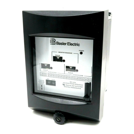
SECTION 2 • CONTROLS AND INDICATORS INTRODUCTION All BE1-47N controls and indicators are located on the front panel. The controls and indicators are shown in Figure 2-1 and described in Table 2-1. Figure 2-1 illustrates a relay with the maximum number of controls and indicators. - Page 16 Instantaneous timing is not user-adjustable, so relays with instantaneous timing do not have an overvoltage time delay switch. The red pickup LED lights when the level of (single-phase) voltage increases above the setting of the overvoltage pickup switch. BE1-47N Controls and Indicators 9170400990 Rev H...
-
Page 17: Section 3 • Functional Description
SECTION 3 • FUNCTIONAL DESCRIPTION INTRODUCTION BE1-47N relay functions are illustrated in Figure 3-1 and described in the following paragraphs. REFERENCE LEVEL TARGET NEGATIVE PHASE PICKUP SEQUENCE PASS SHIFT SCALING VOLTAGE FILTER COMPARATOR TIMING SEQUENCE AUX. FILTER TARGET PASS UNDERVOLTAGE... -
Page 18: Pickup Scaling
18% (e.g., 13%, 8%, etc.) has no effect on the timing characteristic. In other words, the timing curve beginning is dependent upon the monitored voltage percent difference from the system’s nominal voltage. Inverse timing characteristics preceding this defined point are nonexistent. BE1-47N Functional Description 9170400990 Rev H... - Page 19 MULTIPLES OF PICK-UP SETTING 1000 D2818-17 MULTIPLES OF PICK-UP SETTING 07-31-98 Figure 3-2. Negative Sequence Voltage Inverse Time Characteristic Curves 9170400990 Rev H BE1-47N Functional Description...
- Page 20 D2818-15 07-31-98 Figure 3-3. Undervoltage Inverse Time Characteristic Curves BE1-47N Functional Description 9170400990 Rev H...
- Page 21 D2818-16 07-31-98 Figure 3-4. Overvoltage Inverse Time Characteristic Curves 9170400990 Rev H BE1-47N Functional Description...
-
Page 22: Outputs
The power supply status relay has a set of normally closed contacts and energizes when operating power is applied to the BE1-47N. If relay operating power is lost or either side of the power supply output (+12 Vdc or –12 Vdc) fails, the power supply status relay de-energizes and opens the power supply status output contacts. -
Page 23: Indicators
200 milliamperes of current flowing in the trip circuit. NOTE Prior to September 2007, BE1-47N target indicators consisted of magnetically latched, disc indicators. These mechanically latched target indicators have been replaced by the electronically latched LED targets in use today. - Page 24 This page intentionally left blank. BE1-47N Functional Description 9170400990 Rev H...
-
Page 25: Section 4 • Installation
SECTION 4 • INSTALLATION INTRODUCTION BE1-47N relays are shipped in sturdy cartons to prevent damage during transit. Upon receipt of a relay, check the model and style number against the requisition and packing list to see that they agree. Inspect the relay for shipping damage. - Page 26 Figure 4-1. Panel Cutting/Drilling, Semi-Flush Case BE1-47N Installation 9170400990 Rev H...
- Page 27 Figure 4-2. Panel Cutting/Drilling, Single-Ended Projection-Mount Case 9170400990 Rev H BE1-47N Installation...
- Page 28 Figure 4-3. Panel Cutting/Drilling, Double-Ended Projection-Mount Case BE1-47N Installation 9170400990 Rev H...
- Page 29 D1427-29 02/2001 Figure 4-4. Case Dimensions, Side View, Single-Ended Semi-Flush Case 9170400990 Rev H BE1-47N Installation...
- Page 30 D1427-27 12-04-01 Figure 4-5. Case Dimensions, Side View, Double-Ended Semi-Flush Case BE1-47N Installation 9170400990 Rev H...
- Page 31 CASE DETAIL A-A SHOWING THE ADDITION OF WASHERS OVER THE BOSS TO TIGHTEN THE RELAY AGAINST THE PANEL. P0002-17 01-30-01 Figure 4-6. Case Dimensions, Side View, Single-Ended Projection-Mount Case 9170400990 Rev H BE1-47N Installation...
- Page 32 Figure 4-7. Case Dimensions, Side View, Double-Ended Projection-Mount Case BE1-47N Installation 9170400990 Rev H...
- Page 33 Figure 4-8. Case Dimensions, Rear View, Semi-Flush Case 9170400990 Rev H BE1-47N Installation...
- Page 34 Figure 4-9. Case Dimensions, Rear View, Projection-Mount Case 4-10 BE1-47N Installation 9170400990 Rev H...
- Page 35 P0002-12 01-31-01 Figure 4-10. Case Cover Dimensions, Front View 9170400990 Rev H BE1-47N Installation 4-11...
-
Page 36: Connections
Incorrect wiring may result in damage to the relay. Except where noted, connections should be made with wire no smaller than 14 AWG. Typical external connections are shown in Figures 4-11 and 4-12. Typical internal connections are shown in Figure 4-13. Figure 4-11. Control Circuit Diagram 4-12 BE1-47N Installation 9170400990 Rev H... - Page 37 Figure 4-12. Sensing Input Connections 9170400990 Rev H BE1-47N Installation 4-13...
- Page 38 Figure 4-13. Typical Internal Connection Diagram with Optional, Normally-Open Output Contacts 4-14 BE1-47N Installation 9170400990 Rev H...
-
Page 39: Maintenance
MAINTENANCE BE1-47N relays require no preventative maintenance other than a periodic operational check. If the relay fails to function properly, contact Technical Sales Support at Basler Electric to coordinate repairs. STORAGE This protective relay contains aluminum electrolytic capacitors which generally have a life expectancy in excess of 10 years at storage temperatures less than 40°C (104°F). - Page 40 This page intentionally left blank. 4-16 BE1-47N Installation 9170400990 Rev H...
-
Page 41: Section 5 • Testing
Negative Sequence Voltage Pickup and Dropout BE1-47N accuracy verification requires a simultaneous test of the three phases. Such a comprehensive test involves careful monitoring of all phase voltages and phase angles, and the calculation of the negative sequence voltage values. -
Page 42: Overvoltage Pickup And Dropout
Undervoltage Pickup and Dropout 1. Adjust the Undervoltage Pickup switch to the E (10%) position. 2. Apply 0.90 times the nominal input voltage (90%) across case terminals 7 (B-phase) and 8 (C-phase). The Undervoltage Pickup LED should light. BE1-47N Testing 9170400990 Rev H... -
Page 43: Verification Tests
5. Measure and record the interval from initiate to contact closure at case terminals 1 and 10. The 47N inverse time should be 5.96 +0.298 seconds. Further points on the inverse time curves may be verified using the same philosophy. Input voltage values for pickup may be obtained using the equations mentioned previously. 9170400990 Rev H BE1-47N Testing... - Page 44 Figure 5-1. Test Circuit Diagram (47N) Figure 5-2. Test Circuit Diagram (27, 59) BE1-47N Testing 9170400990 Rev H...
- Page 45 ROUTE 143, BOX 269 HIGHLAND, IL 62249 USA http://www.basler.com, info@basler.com PHONE +1 618-654-2341 FAX +1 618-654-2351...
Need help?
Do you have a question about the BE1-47N and is the answer not in the manual?
Questions and answers