
Related Manuals for Rion NL-21


Summary of Contents for Rion NL-21
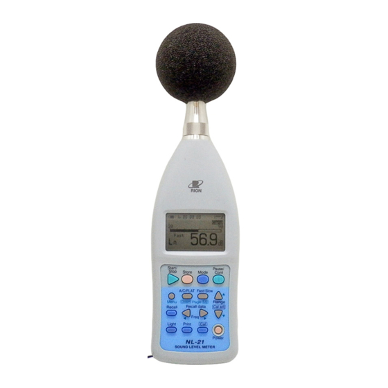
- Page 1 INSTRUCTION MANUAL Sound Level Meter NL-21 / NL-31 3-20-41 Higashimotomachi, Kokubunji, Tokyo 185-8533, Japan http://www.rion.co.jp/english/...
- Page 3 Organization of the NL-21/NL-31 Documentation The documentation for the Sound Level Meter NL-21/NL-31 consists of three separate manuals. Instruction Manual (this document) Describes operating procedures for the Sound Level Meter NL-21/ NL-31, connection and use of peripheral equipment such as a level recorder and printer, and use of the memory card.
- Page 4 To conform to the EU requirement of the Directive 2002/96/EC on Waste Electrical and Electronic Equipment, the symbol mark on the right is shown on the instrument.
- Page 5 Organization of This Manual This manual describes the features, operation and other aspects of the General- Purpose Sound Level Meter NL-21 and High-Precision Sound Level Meter NL-31. The manual contains the following sections. Outline Gives basic information about the configuration and features of the unit, and also contains a block diagram.
- Page 6 Default Settings Lists the factory default settings of the unit. Output Connectors Explains the output connectors of the unit. Optional Accessories Explains how to use external equipment for example to store measure- ment data. Messages Explains the various messages that may appear on the screen. Specifications Lists the technical specifications of the unit.
-
Page 7: For Safety
FOR SAFETY In this manual, important safety instructions are specially marked as shown below. To prevent the risk of death or injury to persons and severe damage to the unit or peripheral equipment, make sure that all instructions are fully understood and observed. Disregarding instructions Caution printed here incurs the risk of... - Page 8 Precautions Operate the unit only as described in this manual. Protect the unit from shocks and vibration. Be especially careful not to touch the microphone membrane to avoid damage. The membrane is an extremely thin metal film which can be damaged easily. Do not use the unit with a different microphone/preamplifier from the one indicated on the name plate of the unit.
- Page 9 Quantifier Notation of Sound Level Meter NL-21/NL-31 According to International Standards and JIS (Excerpts from ISO 1996, 3891, IEC 61672-1:2002, JIS Z 8202, 8731)
-
Page 10: Table Of Contents
Contents FOR SAFETY ..................v Outline ....................1 Controls and Functions ..............4 Front View ..................4 Operation Keys ................5 Bottom View ................. 8 Rear View..................9 Preparations ..................10 Power Supply ................10 Windscreen (WS-10) ..............13 Tripod Mounting ................. 13 Memory Card, Program Card ............. - Page 11 Measurement ..................47 Sound level Measurement ............47 Equivalent Continuous Sound level (L ) Measurement ..50 Sound Exposure Level (L ) Measurement ........ 55 Maximum (L ) and Minimum (L ) Sound level Measurement ..............60 Percentile Sound level (L ) Measurement ........
-
Page 13: Outline
Outline The Sound Level Meter NL-21 and NL-31 are designed for sound level measurements according to the IEC standard. The following measurements can be made: Equivalent continuous sound level Sound exposure level Maximum sound level Minimum sound level Percentile sound level... - Page 14 Outline The following accessories are optional, to cover a wide range of application requirements. Printer DPU-414 Serves to produce hard copy of measurement data (including data stored in memory). Level recorder LR-07/LR-20A Serves to record sound level changes over time.
- Page 15 C L K R S - 2 3 2 - C P O W E R S U P P L Y C A R D I N T E R F A C E NL-21 / NL-31 Block Diagram...
-
Page 16: Controls And Functions
Controls and Functions Front View M i c r o p h o n e / p r e a m p l i f i e r D i s p l a y S t a r t P a u s e S t o p S t o r e... -
Page 17: Operation Keys
Controls and Functions Operation Keys S t a r t P a u s e S t o p S t o r e M o d e C o n t F L A T F a s t S l o w R a n g e M e n u D o w n... - Page 18 Controls and Functions Menu key When this key is pressed, the menu screen 1/5 appears on the display. Pressing the key again switches the display back to the original condition. Menu pages are switched with the Page keys to the right of the D o w n key.
- Page 19 Controls and Functions Print key When the optional printer DPU-414, CP-11, or CP-10 is connected, pressing this key initiates a printout. Cal key Pressing this key activates the built-in oscillator for electrical calibration of the unit or for level matching of the unit and connected equipment. Power key Turns the unit on and off when you hold the key down for more than 1 second.
-
Page 20: Bottom View
Controls and Functions Bottom View O U T P O W E R C o v e r I / O c o n n e c t o r A C / D C o u t p u t j a c k E x t e r n a l p o w e r s u p p l y j a c k Cover This cover protects the connectors on the bottom during transport or storage. -
Page 21: Rear View
Controls and Functions Rear View Card compartment An optional memory card (CompactFlash™ card) can be inserted here. Tripod mounting thread The unit can be mounted on a camera tripod using this thread. Battery compartment Four batteries (IEC R6P, size AA) are inserted here. -
Page 22: Preparations
Preparations Power Supply The unit can be powered by four IEC R6P (size AA) batteries (alkaline or manganese) or by the specified optional AC adapter. It is possible to use size AA rechargeable batteries, but a separate recharger must be provided for such batteries, since the unit is not designed to recharge batteries. - Page 23 Preparations The life of a set of batteries depends on usage conditions and various other factors. Some reference values are shown below. Battery life (23ºC) C o n t i n u o u s u s e A l k a l i n e b a t t e r i e s L R 6 A p p r o x .
- Page 24 Preparations AC adapter (option) Connect the AC adapter as shown below. Important To prevent the risk of damage, do not use any AC adapter other than the NC-98A or NC-34 series (both available as options).
-
Page 25: Windscreen (Ws-10)
Preparations Windscreen (WS-10) When making outdoor measurements in windy weather or when measuring air conditioning equipment or similar, wind noise at the microphone can cause measurement errors. Such effects can be reduced by using the windscreen WS-10. W i n d s c r e e n W S - 1 0 Tripod Mounting For long-term measurements, the unit can be mounted on a camera tripod. -
Page 26: Memory Card, Program Card
Program cards which are memory cards containing software are also available. By loading the software into the NL-21/NL-31, a 1/1 octave or 1/3 octave filter or a 3rd-order Butterworth high-pass and low-pass filter by 1/3-octave step become available. -
Page 27: Microphone Extension Cables (Ec-04 Series)
Preparations Important Be sure to turn the unit off before inserting and removing the card from the unit. Microphone Extension Cables (EC-04 series) Turn power to the unit off before separating the microphone from the main unit. To reduce measurement deviations due to refraction effects and the acoustic influence of the operator, the microphone can be detached from the unit and connected via an extension cable. - Page 28 Preparations 1. Loosen the preamplifier fastening screw and remove the preamplifier from the main unit. Important Never separate the microphone and preampli- fier, because this can lead to damage. Important (NL-31 only) Never remove the microphone grid, because this can lead to damage. Before using the microphone and before putting it away, always check that the microphone grid has not become loose.
-
Page 29: Connection To A Printer (Dpu-414, Cp-11, Cp-10)
Preparations Connection to a Printer (DPU-414, CP-11, CP-10) The I/O port on the bottom of the unit can be used for connection of an optional printer (DPU-414, CP-11, CP-10). Use the optional printer cable CC-93 or CC-93A to connect the I/O port of the unit to the serial input of the printer. I / O c o n n e c t o r O U T P O W E R... - Page 30 An example showing suitable software DIP switch settings for use of the printer with the NL-21/NL-31 is shown below. (The actual printout will be in a different font.) Continue ?
- Page 31 Preparations Setting the software DIP switches of the CP-11/CP-10 Set the baud rate of the sound level meter to 9600 bps on menu screen 3/5. Set the DIP switches of the printer as follows. D I P s w i t c h b a n k 1 D I P s w i t c h b a n k 2 ( 8 s w i t c h e s ) ( 8 s w i t c h e s )
-
Page 32: Connection To A Level Recorder
Preparations Connection to a Level Recorder (LR-06, LR-07, LR-04, LR-20A) Sound level recording Connect the AC/DC output on the bottom of the unit to the level recorder, as shown below. The AC/DC output is selected on the menu screen 3/5. Connection to a Computer Connect the I/O port on the bottom of the unit to the RS-232-C interface of the computer, using the optional Serial I/O cable. -
Page 33: Setting The Date And Time
Preparations Setting the Date and Time The unit incorporates a clock which allows recording the date and time along with measurement data on the memory card or on the unit itself. Set the date and time as described below. 1. Turn the unit on by pressing the Power key. 2. - Page 34 Preparations When there is no card in the card slot < M e m o r y > M a n u a l d a t a c l e a r : O f f < T i m e s e t t i n g > C u r r e n t d a t e D a t e y / m...
-
Page 35: Measurement In Dark Locations
Preparations Measurement in Dark Locations Pressing the Light key turns the display backlight on, making it easier to read in dark locations. Pressing the key once more turns the light off. S t a r t P a u s e O p e r a t i o n k e y s S t o p S t o r e... -
Page 36: Lcd Contrast
Preparations LCD Contrast You can adjust the contrast of the display. 1. Press the Menu key. The display changes to the menu screen. O p e r a t i o n k e y s S t a r t P a u s e S t o p C o n t... -
Page 37: Calibration
Preparations Calibration Before starting a measurement, the unit must be calibrated. There are two types of calibration: electrical calibration and acoustic calibration using a pistonphone. Electrical calibration The built-in oscillator (1 kHz, sine wave) is used for electrical calibration. 1. Turn the unit on by pressing the Power key. 2. - Page 38 Preparations 6. Use the Cal adj keys to set the level display to 114.0 dB. Frequency weighting is temporarily set to "C". When the Cal key is pressed again, the original settings are restored.
- Page 39 Preparations Signal output for calibration of external equipment The normal level range for calibration is 30 to 120 dB, but in order to allow calibration of external equipment, calibration can also be performed at other level range settings. In this case, the "XX dB" indication of the calibration value flashes.
- Page 40 Preparations Acoustic calibration with sound calibrator NC-74 or pistonphone NC-72 For acoustic calibration, the Rion sound calibrator NC-74 or pistonphone NC-72 is mounted to the microphone of the sound level meter, and adjustment is performed so that the reading of the meter is equal to the sound level inside the coupler.
- Page 41 Preparations 5. Press the Menu key again to return to the measurement screen. 6. Use the Level Range keys to select the 30 to 120 dB range. 7. Press the Cal key. Frequency weighting is automatically set to "C". If the level range is not set to 30 to 120 dB, the EXT Cal indication flashes.
-
Page 42: Language Selection
N C - 7 2 N L - 3 1 9 4 . 0 d B 12. Turn off the sound calibrator or the pistonphone and NL-21/NL-31. 13. Remove the microphone very carefully and slowly from the coupler. Note For details on operation of the NC-74 or NC-72, please refer to the instruction manuals for them. -
Page 43: Reading The Display
Reading the Display Display screen The illustration below is for demonstration purposes only. In actual use, not all display elements will be visible at the same time, and the size and font of the display may differ. I n d i c a t e s 1 0 0 h o u r s h a v e e l a p s e d F o r 2 0 0 h o u r s , "... - Page 44 Reading the Display Battery capacity indicator When operating the unit on batteries, periodically check this indicator to determine the remaining battery capacity. The number of black segments decreases as the batteries are used up. When the display starts to flash, correct measurement is no longer possible.
- Page 45 Reading the Display Memory field Shows the selected memory store mode (Manu, Auto 1, or Auto 2). Card insertion indicator This indicator appears when a memory card is inserted. Level range indicator Shows the upper and lower limit of the bar graph. Make the setting that is appropriate for the sound level.
- Page 46 Reading the Display Frequency weighting indicator Shows the selected frequency weighting setting. : FLAT The third and fourth digit are shown when processed values are displayed. The meaning is as follows. Equivalent continuous sound level Sound exposure level Maximum time-weighted sound level Amax Cmax pmax...
- Page 47 Reading the Display Recall indicator Lights up when data stored in memory are being displayed. A u t o R e c a l l i n d i c a t o r C a r d R e c a l l M e m o r y a d d r e s s R e c a l l s c r e e n Measurement screen examples...
-
Page 48: Menu Screens
Reading the Display Menu screens There are five menu screens numbered 1/5 through 5/5. Menu screen 1/5 M e a s u r e m e n t t i m e s e t t i n g < S y s t e m > ( a c t u a l m e a s u r e m e n t t i m e ) M e a s . - Page 49 Reading the Display When optional filter program is installed Filter On/Off When set filter to On, one of the following indications appears, depending on the installed filter type. M e a s u r e m e n t t i m e s e t t i n g <...
- Page 50 Reading the Display Cutoff frequency of the high-pass filter can be changed with key on the measurement screen. Cutoff frequency of the low-pass filter can be changed with key on the measurement screen. Important Auxiliary processing function does not work when set the 1/1 or 1/3 octave filter and univer- sal filter to On.
- Page 51 Reading the Display Menu screen 2/5 < S t o r e > S t o r e M o d e S t o r e m o d e M a n u a l F i l e n a m e : M A N _ 1 2 3 4 F i l e n a m e M e n u s c r e e n 2 / 5...
- Page 52 Reading the Display Menu screen 3/5 LCD Contrast The number of * symbols corresponds to the contrast setting. It can be changed with the keys. Baud rate (I/O transfer speed) You can select 4800 bps, 9600 bps or 19200 bps with the keys.
- Page 53 Reading the Display Menu screen 4/5 L e q : E q u i v a l e n t c o n t i n u o u s s o u n d l e v e l L E : S o u n d e x p o s u r e l e v e l <...
- Page 54 Reading the Display Note , and L can only be chosen when A Atm5 AIeq weighting is selected for main processing. If C weight- ing is selected, the L auxiliary processing func- tion does not operate. When not using the auxiliary processing functions, set the display of auxiliary processing values to Off.
- Page 55 Reading the Display Menu screen 5/5 Card Format On/Off This item is shown when there is a card in the card slot. S h o w n w h e n " C a r d F o r m a t " <...
- Page 56 Reading the Display Manual data clear On/Off This item is shown when there is no card in the card slot. S h o w n w h e n " M a n u a l < M e m o r y > d a t a c l e a r "...
-
Page 57: Power On/Off
Power On/Off Power-on Turn the unit on by holding down the Power key for at least one second. When the power-on screen appears, release the Power key. After the initial screen was shown, the unit switches to the measurement screen. S t a r t P a u s e S t o p... - Page 58 Power On/Off Power-off Turn the unit off by holding down the Power key for at least one second. When the power-off screen appears, release the Power key. S e e Y o u P o w e r - o f f s c r e e n Note Wait at least 5 seconds after turning the unit off be- fore you turn it on again.
-
Page 59: Measurement
Measurement When using this unit in a mode other than sound level measurement, all processing functions provided by the unit are carried out simultaneously. (However, only the auxiliary processing function set to "On" on the Menu screen 4/5 "Display" screen is carried out.) For example, when equivalent continuous sound level measurement is selected, the sound exposure level and percentile level are also determined. - Page 60 If "L " (Flat) is selected, the sound level from 20 Hz to 12.5 kHz for NL-31 and from 20 Hz to 8 kHz for NL-21 can be measured. When L is selected for display, the sound level from 31.5 Hz to 8 kHz is measured with flat characteristics.
- Page 61 Measurement M a n u 1 2 0 U n d e r - r a n g e O v e r - r a n g e F a s t s i g n a l i n d i c a t o r s i g n a l i n d i c a t o r M e a s u r e m e n t s c r e e n 6.
-
Page 62: Equivalent Continuous Sound Level
Measurement Equivalent Continuous Sound level (L ) Measurement The procedure for equivalent continuous sound level measurement is described below. Preparations as described in the previous chapter must be completed first. 1. Turn the unit on by pressing the Power key. 2. - Page 63 This unit uses high-speed sampling of the sound pressure waveform for L and L processing (NL-21: 30.3 µs, NL-31: 20.8 µs). The result is therefore unaffected by dynamic characteristics and accurate also for a short time period. The auxiliary processing function for equivalent impulse sound level is affected by the dynamic characteristics.
- Page 64 Measurement 6. Use the keys to move the cursor to the "Meas. time" item, and use the keys to select the measurement time. Manual → 10 sec → 1 min → 5 min → 10 min → 15 min → 30 min →...
- Page 65 Measurement 10. Press the Start/Stop key to start the measurement. During measurement, the symbol flashes and the elapsed measurement time is displayed. M e a s u r e m e n t t i m e E l a p s e d m e a s u r e m e n t t i m e M e a s u r e m e n t s y m b o l M a n u P a u s e s y m b o l...
- Page 66 Measurement M a n u F a s t D a t a r a n g e t o b e e x c l u d e d 2 0 s 5 9 . 1 M e a s u r e m e n t s c r e e n 11.
-
Page 67: Sound Exposure Level (Lae ) Measurement
Measurement Sound Exposure Level (L ) Measurement The procedure for sound exposure level measurement is described below. It is very similar to the measurement of equivalent continuous sound level. Preparations as described in the previous chapter must be completed first. 1. - Page 68 This unit uses high-speed sampling of the sound pressure waveform for L and L processing (NL-21: 30.3 µs, NL-31: 20.8 µs). The result is therefore unaffected by dynamic characteristics and accurate also for a short time period. 5. Use the menu to set the measurement time.
- Page 69 Measurement 7. Use the Page Up/Down keys to display the menu screen 4/5. If L : Off is displayed, use the keys to move the highlight to "Off", and use the keys to set the item to "On". < D i s p l a y > L e q : O n : O f f...
- Page 70 Measurement When the measurement time set in step 6 has elapsed, the measurement terminates automatically. When wishing to terminate the measurement earlier, press the Start/Stop key. If no display (arbitrary measurement time) was selected, the Start/Stop key must be used to conclude the measurement. If an under-range condition or over-range condition occurs at least once during measurement, the "...
- Page 71 Measurement 11. When the measurement is completed, you can use the Mode key to switch between various ways of displaying the measurement result. When L is shown, the sound exposure level is being displayed. If L is not shown, check whether L on the "Display"...
-
Page 72: Measurement
Measurement Maximum (L ) and Minimum (L ) Sound level Measurement The procedure for maximum and minimum sound level measurement is described below. Preparations as described in the previous chapter must be completed first. 1. Turn the unit on by pressing the Power key. 2. - Page 73 Measurement S t a r t P a u s e / C o n t k e y P a u s e C o n t S t o p S t o r e M o d e A / C / F L A T k e y F a s t / S l o w k e y F L A T...
- Page 74 Measurement < D i s p l a y > L e q : O n : O f f : O n : O f f L m a x : O n : O n : S e t m a x i m u m s o u n d m a x L m i n : O n : O f f...
- Page 75 Measurement If an under-range condition or over-range condition occurs at least once during measurement, the " " (Over) or " " (Under) indicator appears, to show that the processing data contain over-range or under- range data. Important During measurement, most of the keys such as the A/C/FLAT key and Level keys are inopera- tive.
- Page 76 Measurement 11. When the measurement is completed, you can use the Mode key to switch between various ways of displaying the measurement result. When L is shown, the maximum sound level is being displayed. Amax When L is shown, the minimum sound level is being displayed. Amin If L and L...
-
Page 77: Percentile Sound Level (L N ) Measurement
Measurement Percentile Sound level (L ) Measurement The procedure for percentile sound level measurement is described below. It is very similar to the measurement of equivalent continuous sound level. Preparations as described in the previous chapter must be completed first. 1. - Page 78 Measurement S t a r t P a u s e / C o n t k e y P a u s e C o n t S t o p S t o r e M o d e A / C / F L A T k e y F a s t / S l o w k e y F L A T...
- Page 79 Measurement 7. Use the Page Up/Down keys to display the menu screen 4/5. 8. In the default condition, the unit is set up to measure the percentile sound level L , and L . These settings can be changed to any value between L and L (up to five settings).
- Page 80 Measurement 11. Press the Start/Stop key to start the measurement. During measurement, the symbol flashes and the elapsed measurement time is displayed. M e a s u r e m e n t t i m e E l a p s e d m e a s u r e m e n t t i m e M e a s u r e m e n t s y m b o l M a n u P a u s e s y m b o l...
- Page 81 Measurement During measurement, the Pause/Cont key can be used to pause and resume the measurement. During pause, the pause symbol ( ) is shown. (Any pause intervals and the back-erase time if data back-erase is enabled are not included in the measurement time.) If data back-erase was enabled in step 9, the data are indicated on the display, as shown below.
- Page 82 Measurement If " " (Over) is shown, the sound level data used for processing contained over-range data. If " " (Under) is shown, the sound level data used for processing contained under-range data. M a n u 1 2 0 U n d e r - r a n g e s i g n a l i n d i c a t o r O v e r - r a n g e...
-
Page 83: Measurement Of Auxiliary Processing Values (L Peak , L Cpeak , L Ceq , L Atm5 , Lai , Laieq )
Measurement Measurement of Auxiliary Processing Values (L peak Cpeak Atm5 AIeq This unit can simultaneously measure L plus one of the items listed below. : FLAT peak sound level peak : C-weighted peak sound level Cpeak : C-weighted equivalent continuous sound level : Takt-max sound level Atm5 : Impulse sound level... - Page 84 Measurement Important Auxiliary processing functions cannot be used in conjunction with the optional filters (octave fil- ter, universal filter). The auxiliary processing functions are disabled when the 1/1, 1/3 octave filter or universal filter is On. Set the display of auxiliary processing values to Off, using the dis- play menu screen (4/5).
- Page 85 Measurement 4. Use the Page Up/Down keys to display the menu screen 1/5. Use the keys to move the cursor to the "Meas. time" item, and use the keys to select the measurement time. Manual → 10 sec → 1 min → 5 min → 10 min → 15 min → 30 min →...
- Page 86 Measurement 6. Press the Menu key to return to the measurement screen. 7. Use the Level Range keys to select the level range. Choose a setting in which the bar graph indication registers to about the middle of the range. If the "...
- Page 87 Measurement During measurement, the Pause/Cont key can be used to pause and resume the measurement. During pause, the pause symbol ( ) is shown. (Any pause intervals and the back-erase time if data back-erase is enabled are not included in the measurement time.) If data back-erase was enabled in step 5, the data are indicated on the display, as shown below.
- Page 88 Measurement Important is the time weighting level, but the display is updated when processing is started by pressing the Start key. When processing stops, the dis- play update also stops. To measure L only, setting of the "Meas. time" item to "Manual" is recommended.
-
Page 89: Back-Erase Function
Measurement Back-Erase Function When a measurement is being carried out and data are being processed, the Pause/Cont key can be used to pause the measurement (i.e. to exclude data from the point at which the key has been pressed), but it is also possible to exclude (back-erase) data from an interval of 5 seconds before the key was pressed. - Page 90 Measurement Note When L , is selected as auxiliary processing func- Atm5 tion, the data exclusion function cannot be used. The function also cannot be used during Auto1 store or Auto 2 store.
-
Page 91: Store Operations
Store Operations The NL-21/NL-31 incorporates a memory which can be used to store measurement data (sound level, L and other processed values, measurement parameters such as frequency weighting, time weighting, etc.). This chapter describes how to store data in memory and how to recall data from memory. - Page 92 Store Operations Important Never turn off the unit or remove the memory card while a store operation is in progress. Oth- erwise internal data can be destroyed. While a memory card is inserted in the card slot, the internal memory cannot be accessed, which means that data cannot be stored in the memory or read or printed from the memory.
-
Page 93: Manual Store
Store Operations Manual Store Storing Data in Memory At the point where you press the Store key, the current sound level and all processed values are saved. Immediately after turning the unit on, no processing results exist. Therefore only the sound level gets stored. If no memory card is inserted, data are stored in the internal memory. - Page 94 Store Operations 3. Press the Menu key to call up the menu screen. 4. Use the Page Up/Down keys to display the menu screen 2/5. 5. If the Store Mode item is not set to "Manual", use the keys to move the highlight to the item and use the keys to set it to "Manual".
- Page 95 Store Operations 9. To store processed values, perform the measurement as described in the preceding chapter (except for "Sound level Measurement"). 10. Select the data number for the store process. The data number is shown on the screen. You can use the keys to set the data number to a value between 1 to 100.
- Page 96 Store Operations 11. Press the Store key. The sound level at point when the key was pressed is stored. If processing measurement was carried out in step 9, the processed data are also stored in the same way. The store process is completed in about one second, and the data number is incremented by 1.
- Page 97 Store Operations Reading Stored Data (From Internal Memory) To read data stored in the internal memory with manual mode, proceed as follows. Important When the memory card is inserted in the card slot, the data stored in the internal memory can- not be read.
- Page 98 Store Operations Reading Stored Data (From Memory Card) To read data stored in the memory card with manual mode, proceed as follows. Verify that the memory card is inserted in the card slot. 1. Turn the unit on. 2. Press the Recall key to bring up the card recall screen. The data are sorted by measurement start time, in descending order.
- Page 99 Store Operations Clearing Stored Data (From Internal Memory) To clear data stored in the internal memory with manual mode, proceed as follows. 1. Verify that no memory card is inserted in the card slot. 2. Press the Menu key to call up the menu screen. 3.
- Page 100 Store Operations Clearing Stored Data (From Memory Card) To clear data stored in the memory card with manual mode, proceed as follows. 1. Verify that the memory card is inserted in the card slot. 2. Press the Menu key to call up the menu screen. 3.
-
Page 101: Auto 1
Store Operations Auto 1 Using an optional memory card (compact flash card) allows storing sound level data for up to 200 hours of measurement (when set the sampling period to 1 s or L Aeq, 1 sec Storing Data The procedure for Auto 1 storing is as follows. Verify that the memory card is inserted in the card slot. - Page 102 Store Operations 7. Use the "Auto 1 Samp." item to set the sampling interval for the sound level or equivalent continuous sound level. Use the key to move the highlight, and use the keys to select the setting. For sound level measurement, you can select 100 ms, 200 ms, or 1 s. For equivalent continuous sound level measurement, the L setting Aeq,1 sec...
- Page 103 Store Operations 13. Press the Store key. For normal Auto 1 store, lights up for 1 second, and the S t a r t S t o r e indication flash to indicate that store is being carried out. The elapsed time is also shown.
- Page 104 Store Operations Important During store, most of the keys such as the A/C/ FLAT key and Fast/Slow key are inoperative. Only the following three keys can be used: Start/Stop, Pause/Cont, Light. All other settings must be made before starting the store. During store, the Pause/Cont key can be used to pause and resume the store.
- Page 105 Store Operations 15. The timer mode measurement has completed normally, the indication below is shown. T i m e r m o d e m e a s u r e - m e n t i s c o m p l e t e d P u s h a n y K e y Elapsed time display During Auto 1 store, the store address is converted into elapsed time for display.
- Page 106 Store Operations Reading Stored Data To read data stored in Auto 1 mode, proceed as follows. Verify that the memory card is inserted in the card slot. 1. Turn the unit on. 2. Press the Recall key to bring up the card recall screen. The data are sorted by measurement start time, in descending order.
-
Page 107: Auto 2
Store Operations Auto 2 Using an optional memory card (compact flash card) allows continuous storing of up to 99999 data sets of processed values. One data set comprises the equivalent continuous sound level, sound exposure level, maximum value, minimum value, and percentile sound level (5 selectable values), resulting in a total of 9 data. - Page 108 Store Operations 5. Use the key to select "File name". 6. Specify the last four digits of "AU 2_0000" with the keys to set the file name. For normal Auto 2 store without using the timer mode, proceed to step 11. 7.
- Page 109 Store Operations 9. Use the Page Up/Down keys to display the menu screen 1/5. Use the keys to move the cursor to the "Meas. time" item, and use the keys to select the measurement time. Manual → 10 sec → 1 min → 5 min → 10 min → 15 min → 30 min →...
- Page 110 Store Operations Normal Auto 2 store S t o r e S t a r t lights up for 1 second, and the indication flash to indicate that store is being carried out. The elapsed time (time that 1 data set has been measured) is also shown.
- Page 111 Store Operations When Timer Auto 2 is used The Auto 2 standby screen as shown below is displayed, and the unit goes into power save mode. Note In power save mode, power consumption is about 1/3 as compared to regular operation. When you press the Start/Stop key or the Store key in power save mode, measurement is terminated.
- Page 112 Store Operations 17. The timer mode measurement has completed normally, the indication below is shown. T i m e r m o d e m e a s u r e - m e n t i s c o m p l e t e d P u s h a n y K e y...
- Page 113 Store Operations Reading Stored Data To read data stored in Auto 2 mode, proceed as follows. Verify that the memory card is inserted in the card slot. 1. Turn the unit on. 2. Press the Recall key to bring up the card recall screen. The data are sorted by measurement start time, in descending order.
- Page 114 Store Operations Note When auxiliary processing item L is selected for Auto 2 store data. For L the level value at the moment when the mea- surement time has elapsed and data are entered in the respective address is stored. Timer operation example Because the timer of this unit does not allow setting the year, a setting such as shown below will result in measurement end after about a year.
-
Page 115: Memory Card
Memory Card Memory Card Using a memory card Open the card compartment and insert the memory card. To remove the card, push the lever in. L i g h t l y p r e s s h e r e a n d s l i d e t o t h e r i g h t C o n n e c t o r s e c t i o n L e v e r I n s e r t c a r d w i t h c o r r e c t... -
Page 116: Data Size
Memory Card Data size The necessary data size for Auto 1 store For example, when wishing to carry out the measurement with 100 msec sampling for 24 hours, the necessary data size is 11.5 MBytes from the above table. The necessary compact flash card size is 11.5 MBytes and more for this measurement. - Page 117 Some memory cards differ in specifications even if they are the same type from the same manufacturer. Correct function therefore is not assured if using other cards except those optional from Rion. Be sure to use only Rion cards. Note...
-
Page 118: Store Data Format
Memory Card Store Data Format Data stored on the memory card are in CSV format. The files on the card are stored in different subdirectories which are created automatically. Manual store The file name entered via the menu screen is used for the last 4 characters of the subdirectory name. - Page 119 Memory Card...
- Page 120 Memory Card Auto 1 store The file name entered via the menu screen is used for the last 4 characters of the subdirectory name and the header file name. \ A U 1 _ 2 3 4 5 F i l e n a m e e n t e r e d v i a m e n u b e c o m e s s u b d i r e c t o r y n a m e A U 1 - 2 3 4 5 .
- Page 121 Memory Card The header file contains measurement parameters and other information. The data file contains the sound pressure level, over-range information ("O"), under-range information ("U"), and pause information ("P") in CSV format. Line returns are <CR><LF>. One file contains up to 60,000 data. When this number is exceeded, a new file is created.
- Page 122 Memory Card Auto 2 store The file name entered via the menu screen is used for the last 4 characters of the subdirectory name and the header file name. \ A U 2 _ 3 4 5 6 F i l e n a m e e n t e r e d v i a m e n u b e c o m e s s u b d i r e c t o r y n a m e A U 2 - 3 4 5 6 .
-
Page 123: Default Settings
Default Settings The factory default settings of the unit are listed below. Fast/Slow (time weighting) Fast A/C/FLAT (frequency weighting) Level Range 30 to 120 Mode Store Mode Manual Meas. Time 10 min Auto 1 100 ms Timer mode Back Erase LCD Contrast ***** - - I/O Baud Rate... -
Page 124: Output Connectors
Output Connectors AC Output An AC signal corresponding to the frequency-weighted signal is output. When the optional filter is installed, the output signal corresponds to the signal routed through the filter. Output voltage: 1 Vrms ±50 mV rms (scale upper limit) Output impedance: approx. -
Page 125: Dc Output
Output Connectors DC Output A level-converted DC signal generated by rms detection and logarithmic compression is output. The signal reflects the frequency weighting and time weighting settings of the unit. Output voltage: 2.5 V ±50 mV (scale upper limit), 0.25 V / 10 dB Output impedance: approx. -
Page 126: I/O Connector
Output Connectors I/O Connector This input/output connector serves for input of control signals and input/output of measurement data. The following types of cable can be connected. • Printer cable: CC-93 (for DPU-414) CC-93A (For CP-10, CP-11) • Interface cable: CC-92 For communication with a computer •... -
Page 127: Optional Accessories
Optional Accessories Microphone Extension Cables EC-04 Series For measurements requiring special precision, the microphone can be removed from the main unit and connected by means of an extension cable. This reduces measurement deviations due to refraction effects and the acoustic influence of the operator. -
Page 128: Printer Dpu-414/Cp-11/Cp-10
The procedure for printing is described below. Before starting, connect the printer to the NL-21/NL-31, turn both units on, and set the printer to the on- line condition. Preparations as described in the chapter "Preparations" (page 10) should also be completed. - Page 129 Optional Accessories 3. Press the Print key. Sample printout S a m p l e p r i n t o u t A c t u a l f o n t a n d s i z e w i l l b e d i f f e r e n t . Printing out data during a measurement (sound level) A hard copy of the screen is printed out.
- Page 130 Optional Accessories Printing out data stored with manual mode in the internal memory The following explanation assumes that data have been stored in the memory of the unit. For an explanation of the store process, see the section "Store Operations". To print out the data, proceed as follows.
- Page 131 Optional Accessories 4. Press the Print key. The printout contents will vary, depending on the contents (sound level value or processed values) shown on the display. When processed values are displayed Example 5. To terminate the recall mode, press the Recall key again.
- Page 132 Optional Accessories Printing out data stored with Auto 1 mode in the optional memory card Note When carrying out Auto 1 and Auto 2 mode, the data cannot be stored in the internal memory. The following explanation assumes that data have been stored in the optional memory card.
- Page 133 Optional Accessories 7. Press the Print key. 100 data sets, starting with the selected data, will be printed out. Example S a m p l e p r i n t o u t If the following conditions have occurred, the alphabet or the mark as shown below is printed after the sound level.
- Page 134 Optional Accessories Printing out data stored with Auto 2 mode in the optional memory card The following explanation assumes that data have been stored in the optional memory card. For an explanation of the store process, see the section "Store Operations".
- Page 135 Optional Accessories 6. Use the keys to select the data for printout. D a t a N o . A u t o C a r d 1 4 : 2 5 : 3 0 F a s t P e q R e c a l l s c r e e n ( A u t o 2 ) 7.
-
Page 136: Level Recorder Lr-06/Lr-07/Lr-04/Lr-20A
Sound level recording The procedure for noise level recording on a level recorder is described below. Before starting, connect the level recorder to the NL-21/NL-31 and turn power on. Preparations as described in the chapter "Preparations" (page 20) must also be completed. For details regarding use of the level recorder, please refer to its documentation. - Page 137 9. Use the Level Range keys to select the level range. Choose a setting in which the "Over" or "Under" indication does not appear. The upper limit of the level range selected at the NL-21/NL-31 becomes the full-scale point of the level recorder.
-
Page 138: Program Cards
(factory default). The software on the program card are protected, to ensure that the card cannot be used for several sound level meters simultaneously. The software from only one program card can be loaded into the NL-21/NL-31. - Page 139 Optional Accessories Loading and unloading the program from a program card Important Make sure that power to the NL-21/NL-31 is turned off before starting the load procedure. Make sure the following points before loading/unloading the program to sound level meter.
- Page 140 Optional Accessories 1. Open the card compartment and insert the program card. S t a r t P a u s e S t o p S t o r e M o d e C o n t P a u s e / C o n t k e y F L A T F a s t S l o w D o w n...
- Page 141 Optional Accessories Universal filter was unloaded (removed from sound level meter) The card was not used for loading the program (unloaded) and can be used to load the program to sound level meter. " Universal filter program has unloaded. Push any key " 1/1, 1/3 octave filter was loaded (incorporated in sound level meter) The card was used for loading the program (loaded) and cannot be used to load the program to another sound level meter.
- Page 142 If a memory content mismatch was detected during the load or unload process. If software from another program card was already loaded into the sound level meter. " This is not a RION program card. Push any key " If the contents were already loaded to another sound level meter.
- Page 143 1/1, 1/3 Octave Filter Card NX-21SA Linearity range during filter operation is 65 dB. Supported standard: IEC 61260:1995 Class 1 1/1 octave filters (IEC compatible) Installed in NL-21: 16 Hz to 8 kHz Installed in NL-31: 16 Hz to 8 kHz...
- Page 144 Optional Accessories Important Auxiliary processing and the optional filter (oc- tave filter, universal filter) cannot be used to- gether. When the 1/1 octave filter, 1/3 octave filter, or universal filter is set to "On", auxiliary process- ing will not work. You should therefore set the auxiliary processing function on the display menu screen 4/5 to "Off".
- Page 145 1/3 octave steps Linearity range during filter operation is 65 dB. HPF cutoff frequencies (-3 dB) Installed in NL-21: 10 Hz to 8 kHz Installed in NL-31: 10 Hz to 12.5 kHz LPF cutoff frequencies (-3 dB) Installed in NL-21: 10 Hz to 8 kHz Installed in NL-31: 10 Hz to 12.5 kHz...
- Page 146 Optional Accessories Select the "Filter" item on menu screen 1/5, and set it to "Univ". Use the frequency keys to switch the cutoff frequency (1/3 octave steps). key shifts the frequency (high-pass filter cutoff frequency) to the next higher band. NO ⇒...
- Page 147 Optional Accessories Important If the optional filter is set to "On", auxiliary pro- cessing cannot be used. The auxiliary process- ing value will be 00.0 dB even if the function is set to "On". However, if the filter is set to "On" but "AP" (oc- tave filter) or "Off-Off"...
-
Page 148: Messages
Messages This chapter explains various messages that may be displayed by the unit during operation. Any steps that should be taken are also explained. English Deutsch Español File open error Can not open file Datei kann nicht No se puede abrir or memory full! geöffnet werden! archivo o lleno. - Page 149 Messages Card read error Error in reading Lesefehler Error de lectura from card! von Karte! en tarjeta! Push any key. Taste drücken. Presione un botón. Data read was attempted, but card was removed. <User action> Do not remove card during read or write access. Card write error Error in writing Schreibfehler...
- Page 150 Messages No recall data No recall data! Keine gespeicherte No hay datos Daten vorhanden! que recuperer. Push any key. Taste drücken. Presione un botón. There are no data stored on the memory card. Recall data are being checked Checking card… Karte wird Está...
- Page 151 Messages Data number 100 reached during manual store (memory card) Data count has Datennummer Contador de datos reached 100. 100 erreicht. ha llegado a no 100 Change Data Number. Datennummer ändern. Cambiar no de dato. Push any key. Taste drücken. Presione un botón.
- Page 152 Messages Timer mode setting error Reset interval time Intervalldauer oder Resetear intervalo or measurement time. Meßdauer neu de tiempo. eingeben. Settings are Ajuste de intervalo inconsistent. inconsistente. Push any key. Taste drücken. Presione un botón. Measurement time is longer than interval time for timer mode. <User action>...
-
Page 153: Specifications
Specifications Applicable standards Sound Level Meter NL-21 IEC 61672-1:2002 Class 2 JIS C 1509-1:2005 Class 2 IEC 60651 and IEC 60804 was withdrawn and replaced by IEC 61672-1:2002. JIS C 1502 was withdrawn and replaced by JIS C 1509-1. Sound Level Meter NL-31... - Page 154 55 dB to 141 dB Peak sound level (FLAT): 60 dB to 141 dB Noise floor NL-21 NL-31 A weighting: 22 dB or less 20 dB or less (19 dB Typ.) (17 dB Typ.) C weighting: 27 dB or less 25 dB or less...
- Page 155 50 to 110 dB 60 to 120 dB 70 to 130 dB Frequency range Overall characteristics including microphone: NL-21: 20 to 8000 Hz NL-31: 20 to 20000 Hz Electrical circuit characteristics (AC output): NL-21: 10 to 20000 Hz NL-31: 10 to 20000 Hz...
- Page 156 Specifications Data store functions For manual store, data can be stored either in the internal memory or on the CompactFlash memory card. Auto store is possible only when the optional memory card is inserted, because data are stored directly on the card.
- Page 157 Specifications Microphone and preamplifier 1/2-inch prepolarized condenser type NL-21 NL-31 Model: UC-52 UC-53A Sensitivity: -33 dB -28 dB Preamplifier NH-21 Display Backlit LCD (128 × 64 dots + 121 icons) Display screens Numeric and bar graph indication of sound level...
- Page 158 Level setting range: 30 to 130 dB, 1-dB steps Power requirements Four IEC R6P (size "AA") batteries Battery life (23°C) NL-21: Approx. 32 h (alkaline batteries), 12 h (manganese batteries) NL-31: Approx. 27 h (alkaline batteries), 10 h (manganese batteries) With backlighting, battery life is reduced to about half.
- Page 159 Specifications Current rating NL-21: Approx. 55 mA NL-31: Approx. 65 mA Current consumption in standby mode is reduced to about one third. Operating input voltage: 4.2 V to 6.5 V Internal backup battery retains clock for about 1.5 months without external...
- Page 160 Specifications Supplied accessories Windscreen WS-10 Carrying case (Product name label, Logo label) NL-21-031 Connector cover (mounted on unit) NL-21-005 Hand strap VM-63-017 Batteries IEC R6P Inspection Certificate Instruction manuals 1 set (Instruction Manual, Technical Notes, Serial Interface Manual, 1 each)
- Page 161 Linearity range during filter operation is 65 dB. Supported standard: IEC 61260 : 1995 Class 1 1/1 octave filters (IEC compatible) Installed in NL-21: 16 Hz to 8 kHz Installed in NL-31: 16 Hz to 8 kHz 1/3 octave filters (IEC compatible) Installed in NL-21: 12.5 Hz to 10 kHz...
- Page 162 Specifications Unit: mm Dimensional Drawings (Illustration shows NL-21)
- Page 164 No. 32005 06-04 Printed in Japan...
Need help?
Do you have a question about the NL-21 and is the answer not in the manual?
Questions and answers