
Related Manuals for Rion NX-43EX


Summary of Contents for Rion NX-43EX
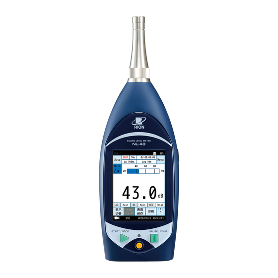
- Page 1 Class 1 Sound Level Meter NL-53 Class 2 Sound Level Meter NL-43 with Extended Function Program NX-43EX Instruction Manual Operation Guide...
-
Page 3: Organization Of The Nl-43/Nl-53 Instruction Manual
This manual describes the basic handling of Sound Level Meter NL-43/NL-53. Operation Guide (This Document) This manual describes how to use Sound Level Meter NL-43/NL-53 (with Extended Function Program NX-43EX), how to connect and use peripheral devices such as sound level recorders and printers, and what to do when using an SD card. -
Page 4: Organization Of This Manual
Organization of This Manual This manual describes the functions and operation method of the Class 2 Sound Level Meter NL-43 and Class 1 Sound Level Meter NL-53. When the measuring system is configured with other equipment, make sure to read the instruction manual of the equipment for how to operate the other equipment. -
Page 5: About Extended Function Program Nx-43Ex
About Extended Function Program NX-43EX By installing the Extended Function Program NX-43EX, the following functions are added to the NL-43/NL-53. • Auto store function (including Maker function) • I-time-weighted calculation function • Comparator function • Trigger function for measurement start •... -
Page 6: Safety Precautions / Precautions For Use
Safety Precautions / Precautions for Use Safety precautions The precautions shown here are intended to help you use the product safely and correctly, and to prevent harm and damage to you and other people. Incidents that could occur as a result of incorrect handling are divided into two categories: “WARNING”... - Page 7 The operating temperature for this device is -10°C to +50°C and the humidity range is 10% to 90% RH. * In the event of a product defect caused by RION, RION will repair or replace the device.
-
Page 8: Precautions For Use
Safety Precautions / Precautions for Use Precautions for use • Avoid using and storing the product in places with high temperatures and humidity, or in places exposed to direct sunlight for long periods of time. • If there is a drastic change in the surrounding temperature, the product may malfunction due to internal condensation. •... - Page 9 • RION shall not be held accountable for the following incidental damages arising from the use or inability to use this product: Alteration or loss of recorded content, loss of business profits, or the interruption of business, etc.
-
Page 10: Table Of Contents
Contents Organization of the NL-43/NL-53 Instruction Manual Organization of This Manual About Extended Function Program NX-43EX ………………………………………………………………… 5 Safety Precautions / Precautions for Use Safety precautions ……………………………………………………………………………………………… 6 Precautions for use ……………………………………………………………………………………………… 8 Overview of This Product Terminology and Notation... - Page 11 6.5.6 Back Erase (Manual mode) …………………………………………………………………… 55 6.5.7 Delay Time (Manual mode, Auto mode) ……………………………………………………… 55 6.5.8 Trigger Mode (Manual mode, Auto mode) ………………………………………… 56 NX-43EX NX-43EX 6.5.9 LN Mode (the same for each mode) ………………………………………………………… 56 6.5.10 Total Meas. Time (Auto mode) ………………………………………………………...
- Page 12 6.6.5 LAN ……………………………………………………………………………………… 68 NX-43EX NX-43EX Save/Load Settings ……………………………………………………………………………………… 69 6.7.1 Saving settings …………………………………………………………………………………… 70 6.7.2 Loading settings ………………………………………………………………………………… 72 6.7.3 Renaming the settings file ……………………………………………………………………… 73 6.7.4 Deleting the settings …………………………………………………………………………… 74 6.7.5 Startup settings ………………………………………………………………………………… 75 Changing the language ………………………………………………………………………………… 76 Restoring factory default settings ………………………………………………………………………...
- Page 13 Connecting the AC/DC output ports ………………………………………………………………… 131 8.7.1 AC OUT (AC output) ………………………………………………………………………… 131 8.7.2 DC OUT (DC output) ………………………………………………………………………… 135 Connection with level recorder or data recorder ………………………………………………… 138 Computer connection ………………………………………………………………………………… 145 Calibration 10 Measurement 10.1 Setting the date and time …………………………………………………………………………… 150 10.2 Checking the sound level ( L ) (current state) ………………………………………………………...
-
Page 14: Overview Of This Product
Overview of This Product • Class 2 Sound Level Meter NL-43 and Class 1 Sound Level Meter NL-53 are a class 1 sound level meter and a class 2 sound level meter that comply with the following laws and regulations related to sound level meters: the Measurement Act, IEC, JIS, and ANSI/ASA. - Page 15 ✓ ✓ Instantaneous Time-weighted sound pressure level value ✓ Equivalent continuous sound level – ✓ ✓ I-time-weighted equivalent continuous sound level NX-43EX NX-43EX ✓ Moving L eq, mov – NX-43EX NX-43EX ✓ Sound exposure level – ✓ ✓...
-
Page 16: Terminology And Notation
Time weighting Notation and name Frequency Measurement value I-weighting with NL-43/NL-53 weighting F-weighting S-weighting NX-43EX NX-43EX A-weighting A-weighted sound pressure level C-weighting C-weighted sound pressure level Sound pressure level Z-weighting Z-weighted sound pressure level Equivalent continuous A-weighted sound level –... - Page 17 Terminology and Notation The notation of quantifiers in international standards and JIS with Sound Level Meter NL-43/NL-53 Quantifiers are taken from ISO 1996, IEC 61672-1, JIS C 1509-1 and JIS Z 8731. Notation and name Frequency ISO 1996 JIS C 1509-1 JIS Z 8731 with NL-43/NL-53 weighting...
-
Page 18: Name And Function Of Each Part
Name and Function of Each Part Front Right side Microphone grid Microphone Preamplifi er START / STOP PAUSE / CONT Operation panel (Page 19) Name Description Microphone and The microphone and preamplifi er can be separated from the main unit. They can be preamplifi er installed at a distance from the main unit using an extension cable (optional). - Page 19 Name and Function of Each Part Operation panel START / STOP START / STOP PAUSE / CONT Name Description Indicator LED Lights or fl ashes red or blue depending on the operation and status of the device. Used when starting or ending measurement. Press the START/STOP key from the current state (sound level display) to enter the START/STOP key measurement state.
- Page 20 Name and Function of Each Part Bottom AC/DC DC 5.7-15V Name Description Bottom cover A cover to protect the ports. Ports can be accessed by opening the bottom cover. This is the port for connecting AC Adapter NE-21P (optional) (input voltage of 100 V to 240 V, 50/60 Hz).
- Page 21 Name and Function of Each Part Back Name Description Serial number label The serial numbers of the microphone, preamplifi er, and sound level meter are listed here. Tripod mounting screw This screw can be used to mount the device to a camera tripod. Install four AA batteries to use the device.
-
Page 22: Turning On The Power
Turning on the Power The device can be operated with four AA batteries (alkaline batteries, Ni-MH rechargeable batteries), or, as an external power supply, AC Adapter NE-21P, Battery Pack BP-21A, or a USB power supply. The operating voltage is 5.7 V to 15 V (rated voltage 12 V). WARNING •... -
Page 23: Inserting The Batteries
Turning on the Power Inserting the batteries WARNING • Make sure to correctly insert the batteries with the polarities of the batteries “+” and “-” matching the marks. If the polarities are incorrect, the batteries may explode or leak. If you do not intend to use the device, remove the batteries to prevent leakage. - Page 24 Turning on the Power Continuous operating time with battery The continuous operating time with batteries will vary depending on the battery manufacturer and type (model), the usage environment of the NL-43/NL-53, and the measurement conditions. For example, the operating time is approximately as follows for continuous measurement in Auto store mode (Page 93 to 105) when set to Eco (the I/O setting is turned off, communication is turned off, Backlight Auto Off is set, etc.
-
Page 25: Connecting An External Power Supply
Turning on the Power Connecting an external power supply The following connection methods are possible for operation using an external power supply. NE-21P Open the bottom cover AC/DC DC 5.7-15V External power supply port AC adapter NE-21P To 100 V to 240 V AC, 50/60 Hz power supply NC-98 series + CC-43J Open the bottom cover... - Page 26 Turning on the Power USB power supply (from mobile battery, computer, etc.) To power the device via USB, connect the USB Type-C cable to the USB port of the computer or USB charger. USB port (Type-C) Open the bottom cover AC/DC DC 5.7-15V To mobile battery...
-
Page 27: Backup Battery
Turning on the Power Backup battery This device is equipped with a backup battery (rechargeable battery) for the clock. The rechargeable battery is charged when the power supply of the main unit is turned on. Even when the power is turned off, the battery will be charged if an external power supply is connected. -
Page 28: Turning On/Off The Power
Turning on the Power Turning on/off the power When turning on the power Press and hold the POWER key for several seconds. Indicator LED Release your fi nger from the POWER key when the startup screen appears. After the startup screen appears, the measurement screen appears. During startup, the indicator LED fl ashes red, blue, and pink in cycles. -
Page 29: Reading The Display
Sound level screen (main channel display) Note • While the actual display may not look exactly like those in the fi gures below, the explanation is based on the assumption that the same text will be displayed. NX-43EX NX-43EX Manual Auto or Timer Auto... - Page 30 Total measurement time In the Auto store mode, displays the total measurement time (Page 57). 11-b (Auto) Not displayed in Timer Auto mode. NX-43EX NX-43EX Calculation / measurement 12-a elapsed time Displays the elapsed time since starting measurement in hours, minutes, and seconds.
- Page 31 Z-weighting Displays the time weighting set for each channel. Fast Time weighting Slow Impulse NX-43EX NX-43EX When a sound level under-range condition is detected, the indication is shown for at least 1 second. (White on black) Under-range indication If the calculation contains signal under-range data, the indication is shown.
- Page 32 Reading the Display Name Description Each time you touch the [info] on the menu ring, the displayed information will switch. [info] is displayed by touching [>] on the far right of the menu ring. See the description of the menu ring (Page 33). Displays the frequency weighting of the AC output set in [Signal Output] - [AC OUT] (Page 64 ) on the [I/O] screen.
- Page 33 Reading the Display Name Description Each time you touch [>] on the far right of the menu ring, the displayed menu switches. Sets the upper and lower limits of the bar graph. Range Freq. Sets the frequency weighting for each channel (Page 48). Weight Time Sets the time weighting for each channel (Page 49).
- Page 34 Appears when [I/O Port] is set on the [I/O] screen (Page 62). USB communication Appears when USB is set on the [I/O] screen (Page 62). LAN communication Appears when LAN is set on the [I/O] screen. NX-43EX NX-43EX Date / Current time Displays the current date and time. Note •...
-
Page 35: Sound Level Screen (Sub Channel Display)
Reading the Display Sound level screen (sub channel display) If you set one of the sub channels to [On] on the measurement screen, the sound level L value of the sub channels will be displayed on the measurement screen (Page 48). Main channel sound level L value... -
Page 36: Calculated Value Screen
Reading the Display Calculated value screen The measurement amount set to [On] under [Leq Calc.] on the [Display] screen can be displayed on the calculated values screen (Page 46). Each time you touch [Disp] on the menu ring, the display switches in the order of the sound levels screen » calculated values screen* »... -
Page 37: Time-Level Screen
Reading the Display Time-Level screen The time-level screen can be displayed by setting [Time-Level] on the [Display] screen to a setting other than [Off] (Page 46). Each time you touch [Disp] on the menu ring, the display switches in the order of the sound levels screen » calculated values screen* »... -
Page 38: Message Display
Reading the Display Message display When you press the START/STOP key or PAUSE/CONT key, one of the following messages will be displayed for about 1 second. Message Display Description Appears when the START/STOP key is pressed, and the measurement starts. Appears when the START/STOP key is pressed and measuring is fi nished. -
Page 39: Setting Menu
Displays the screen for loading the data saved on the internal memory or SD card. Option Displays the screen for switching the function of the device to each program if optional NX-43EX NX-43EX programs are installed. You can also install optional programs from here. -
Page 40: System
Sets the user name, password, and key lock (Page 43). System Information Sets the device model, serial number, index, and program version (Page 44). User Manual (QR code) Displays the QR code to RION website for Instruction Manuals (Page 44). -
Page 41: Time And Date
Setting Menu 6.2.1 Time and Date Sets the year, month, day, hour, minute, and second of the built-in clock. Touch [Apply] to apply the settings. Note • Make sure to set the time before taking measurements. 6.2.2 LCD Settings Sets the brightness of the backlight, backlight auto-off time, and LCD auto- off time. -
Page 42: Power
Item Settings in power saving mode Sub Channel Settings Backlight Auto Off LCD Auto Off Brightness AC OUT DC OUT TCP (IO/USB/LAN NX-43EX NX-43EX LCD auto off time during auto store NX-43EX NX-43EX Comparator NX-43EX NX-43EX Note • [LCD Auto Off] is not displayed in Manual mode. -
Page 43: Sd Card
Setting Menu 6.2.5 SD Card Checks the capacity and free space of the SD card inserted in the device, and formats the SD card. This can be selected only when an SD card is inserted. Item Description SD Card Capacity Displays the capacity of the SD card. -
Page 44: System Information
6.2.8 User Manual (QR code) Displays the QR code to RION website for Instruction Manuals. If you load it on your smartphone, etc., you will be taken to the website. *The above QR code is an image. -
Page 45: Display
Setting Menu Display Sets the measurement amount and other items displayed on the measurement screen. Name Description Bar Graph Sets the upper and lower limits of the bar graph (Page 45). Leq Calc. Sets the measurement amount to be displayed on the [Calculated value] screen (Page 46). Time-Level Sets whether to display Time-Level (Page 46). -
Page 46: Leq Calc
Setting Menu 6.3.2 Leq Calc. Sets the measurement amount to be displayed on the measurement screen. The setting switches between turning on/off each time you touch. calculation (statistical calculation for a certain interval such as ) is measured at the same time. Turn and L peak eq, mov... -
Page 47: Measure
Setting Menu Measure Sets the number of measurement channels, correction and other items. Name Description Sub Channel Settings Sets On/Off for sub channel (Sub1 to Sub3) display (Page 48). Frequency Weighting Sets the frequency weighting for each channel (Page 48). Time Weighting Sets the time weighting for each channel (Page 49). -
Page 48: Sub Channel Settings
Setting Menu 6.4.1 Sub Channel Settings When set to [On], the sub channel sound level L is displayed on the measurement screen at the same time as the main channel. The calculated values are also displayed for each channel. Note •... -
Page 49: Time Weighting
It is also commonly used to measure low frequency sounds. Sets I (Impulse). This responds to short, continuous sounds more quickly than F (fast) NX-43EX NX-43EX in the onset. Note • The device uses high-speed sampling (20.8 µs) data for the sound pressure... -
Page 50: Diffuse S.f. Corr
Setting Menu 6.4.5 Diffuse S.F. Corr. Compensates for variations in sensitivity and frequency response in diffuse sound fi elds for free fi elds. Set to [On] when measuring in a diffuse sound fi eld. For details, refer to the “Technical Guide” . Item Description Uses diffuse sound fi eld correction... -
Page 51: Store
Setting Menu Store Sets the store conditions, etc. for saving calculation results. Manual mode NX-43EX NX-43EX NX-43EX NX-43EX Auto mode Timer Auto mode... - Page 52 For the trigger for starting measurement, you can select from a level or an external trigger (Manual, Auto) (Page 56). NX-43EX NX-43EX LN Mode Sets the sampling date and changes the L1 to L99 value for LN1 to LN5 (Page 56).
-
Page 53: Store Mode
Setting Menu 6.5.1 Store Mode Sets the store mode. You can select from [Manual], [Auto], and [Timer Auto]. For details, refer to “Store Operations” (Page 80). 6.5.2 Store Name (the same for each mode) Sets the identifi cation number of the store data. Deletes all entered characters. -
Page 54: Meas. Duration (Manual Mode)
Setting Menu 6.5.4 Meas. Duration (Manual mode) Select the measurement time in Manual mode. If you select [User Setting], you can set the measurement time to a time of your choice. (s = seconds, m = minutes, h = hours) 6.5.5 User Setting (Manual mode) In [Meas. -
Page 55: Back Erase (Manual Mode)
Setting Menu 6.5.6 Back Erase (Manual mode) Sets the function to omit data immediately before the interruption in the calculation when the measurement is interrupted in Manual mode. Once this is set, the setting value is displayed at the top of the screen. Time where back erase is set Measured... -
Page 56: Trigger Mode (Manual Mode, Auto Mode)
Input Cable (CC-43CT) connected to the I/O port are shorted. • Trigger Mode cannot be used together with the following functions. • Delay Time • Web application (when the NX-43EX is installed) • Level recording (when the Waveform Recording Program NX-43WR is installed) • I/O port functions 6.5.9 LN Mode (the same for each mode) -
Page 57: Total Meas. Time (Auto Mode)
Setting Menu 6.5.10 Total Meas. Time (Auto mode) NX-43EX NX-43EX Sets the total measurement time in Auto mode. If you select [User Setting], you can set the measurement time to a time of your choice. When [Continue] is selected, the measurement will continue until the SD card runs out of space. -
Page 58: Leq Calc.interval (Auto Mode, Timer Auto Mode)
Setting Menu 6.5.13 Leq Calc.Interval (Auto mode, Timer Auto mode) NX-43EX NX-43EX Sets the calculation interval of L calculation ( L eq,mov and L ) in Auto mode and Timer Auto mode. peak If you select [User Setting], you can set the value of your choice. -
Page 59: Leq,Mov Interval (Auto Mode, Timer Auto Mode)
Setting Menu 6.5.15 Leq,mov Interval (Auto mode, Timer Auto mode) NX-43EX NX-43EX Sets the calculation interval of Moving L ) calculation in Auto mode eq,mov and Timer Auto mode. If you select [User Setting], you can set the value of your choice. -
Page 60: Start (Timer Auto Mode)
Setting Menu 6.5.17 Start (Timer Auto mode) NX-43EX NX-43EX Sets the measurement start time in Timer Auto mode. When you open the setting screen for the first time, the time five minutes from the current time is displayed. 6.5.18 Stop (Timer Auto mode) -
Page 61: Sleep Mode (Timer Auto Mode)
Setting Menu 6.5.20 Sleep Mode (Timer Auto mode) NX-43EX NX-43EX Sets whether to use sleep mode while measuring in Timer Auto mode. When the sleep mode is [On], after about 30 seconds have passed after pressing the START/STOP key and measuring goes into standby, the device will enter its low-power mode. - Page 62 I/O Port Sets the I/O port on the bottom of the device (Page 65). Sets the USB port on the bottom of the device (Page 68). Sets the LAN port on the bottom of the device (Page 68). NX-43EX NX-43EX...
-
Page 63: Ref. Signal Output
Setting Menu 6.6.1 Ref. Signal Output When set to [On], a reference signal is output from inside the main unit and used for calibrating external devices and wave recording data. is displayed on the screen at this time. Frequency : 1 kHz Output Level : Bar graph range upper limit −... - Page 64 Setting Menu AC OUT Item Description No AC signal is output. Main Outputs an AC signal corresponding to the sound pressure Sub1 waveform after frequency weighting. Sub2 Applies the frequency weighting set in the selected channel. Sub3 Outputs an AC signal corresponding to the sound pressure waveform after frequency weighting.
-
Page 65: I/O Port
DPU-414 or BL2-58. * DPU-414 and BL2-58 are no longer manufactured and sold. Comparator Sets the comparator signal (open collector signal for external NX-43EX NX-43EX device control). When [Communication] is selected Measurement values can be acquired and the baud rate can be changed by using communication commands. - Page 66 DPU-414 or BL2-58. Item Description DPU-414 Select the printer to use from DPU-414 and BL2-58. BL2-58 When [Comparator] is selected NX-43EX NX-43EX The comparator output turns on when the specified channel exceeds the set level. Item Description Channel Select the channel to be subject to the comparator’s judgment.
- Page 67 Setting Menu • Example of comparator output circuit An example of a circuit for controlling a relay by the comparator output of NL-43/NL-53 is shown below. Relay coil NL-43/NL-53 The voltage applied to the relay when the comparator is turned on is per the following formula. Vr : voltage (V) applied to the relay Rr : relay coil resistance (Ω) : power supply voltage (V) of the circuit used...
-
Page 68: Usb
• The USB port can be used for both [Communication] and [Mass Storage]. For details, refer to the “Communication Guide” . 6.6.5 LAN NX-43EX NX-43EX Sets the LAN port on the bottom of the device. The LAN port communicates with the IP address specified by the user or automatically obtained from the router, and it can be controlled by commands, acquire data, and display a web browser. -
Page 69: Save/Load Settings
Setting Menu Save/Load Settings By using a settings file, you can do the following: • By loading a prepared settings file on the internal memory or SD card, you can configure settings accurately and efficiently. • Even if settings are changed accidentally, the settings can be restored by loading a settings file on the internal memory or SD card. -
Page 70: Saving Settings
Setting Menu 6.7.1 Saving settings Touch [Save/Load Settings] on the [Menu] screen. Select where to save the setting fi le. Item Description Memory 1-5 Saves the current settings to the internal memory. Saves the current settings to the internal memory Startup (Internal) as a startup. - Page 71 Setting Menu When saving new settings, the screen shown on the right appears.
-
Page 72: Loading Settings
Setting Menu 6.7.2 Loading settings Select the setting fi le you want to load. Note • Loading a settings fi le overwrites the current settings. • Before loading the settings fi le, we recommend saving the current settings if necessary. Touch [Load settings]. -
Page 73: Renaming The Settings File
Setting Menu 6.7.3 Renaming the settings fi le Select the setting fi le you want to rename. Touch [Change the name]. The [Change the name] screen appears. Enter the name on the [Change the name] screen, and touch [Apply]. (Character limit: 1 to 8 characters) -
Page 74: Deleting The Settings
Setting Menu 6.7.4 Deleting the settings Select the setting fi le you want to delete. Touch [Delete]. The confi rmation screen appears. Note • Touch [Cancel] to return to the [Save/Load Settings] screen. Touch [YES] on the confi rmation screen. The selected setting fi le is deleted. -
Page 75: Startup Settings
Setting Menu 6.7.5 Startup settings If you save the settings in Startup, you can specify to start up the device with those settings. Select either [Startup (Internal)] or [Startup (SD)]. Item Description Saves the current settings to the internal memory Startup (Internal) as a startup. -
Page 76: Changing The Language
Setting Menu Changing the language The language used on this device can be set. Touch [Language] at the bottom of the [Menu] screen. Select a language, and touch [Apply]. The language setting is memorized, and so the message will be displayed in the set language even if the device is turned on and off again. -
Page 77: Restoring Factory Default Settings
Setting Menu Restoring factory default settings To return the settings to the default values, follow the procedure below. Touch [Save/Load Settings] at the bottom of the [Menu] screen. Touch [Default Settings]. Touch [YES] on the confi rmation screen. The setting returns to the default values (Page 78). Note •... - Page 78 Setting Menu Default settings The factory default settings for the main setting items are listed below. For information on how to restore the default values, refer to “Restoring factory default settings” (Page 77). Item Default settings Brightness Backlight Auto Off LCD Auto Off Continue Power...
- Page 79 Time Weighting Sub2 Sub3 Windscreen Correction Diffuse S.F. Corr. Store Mode Manual Store Name 0000 Address 0001 Meas. Duration Store Back Erase Delay Time Trigger Mode NX-43EX NX-43EX Ref. Signal Output AC OUT Signal Output DC OUT I/O Port NX-43EX NX-43EX...
-
Page 80: Store Operation
Important • Use SD cards that are genuine and provided by RION. The performance of other cards is not guaranteed (Page 106). • Do not turn off the power or remove the SD card while in the middle of storing. Doing so may corrupt the data. -
Page 81: Store Operation In Manual Mode
Store Operation Store operation in Manual mode 7.1.1 Saving to internal memory Each calculated value is saved when the store operation is performed on the confi rmation screen at the end of calculation. Note • If an SD card is not inserted, the data will be saved to the internal memory. •... - Page 82 Store Operation On the [Store] screen, touch [Store Mode] and select [Manual]. Set the store name (only when an SD card is inserted). 1. On the [Store] screen, touch [Store Name]. The input screen for the store name appears. 2. Enter the store name (4-digit number). The setting range is from 0000 to 9999.
- Page 83 Store Operation Set the store address 1. On the [Store] screen, touch [Address]. The input screen for the store address appears. 2. Enter the store address (4-digit number). The initial setting is 0001. If there is no problem, no change is required.
- Page 84 Store Operation Touch [Back] or press the START/STOP key to return to the measurement screen. START / STOP PAUSE / CONT Press the START/STOP key on the measurement screen to start measurement. Press the START/STOP key again to end the measurement. After the measurement is completed, the confi rmation screen appears.
-
Page 85: Loading The Saved Data
Store Operation 7.1.2 Loading the saved data Load the data saved to the internal memory in Manual mode. Touch [Menu] on the measurement screen. The [Menu] screen appears. Touch [Recall] on the [Menu] screen. The [Recall] screen appears. Select the location to which to save data from the [Recall] screen. - Page 86 Store Operation Touch the data to read. • The data is listed by store name. • [Meas. Date] is the date and time the measuring was started for the fi rst address measured with the same store name. • [Meas. Date] will not change even if the number of store addresses increases.
- Page 87 Store Operation If there are six or more calculated values, on the menu ring, touch [>] and then touch [Disp] to switch to the next screen after the calculated values screen. • Touch [Menu] to check the measurement and store settings. •...
-
Page 88: Deleting The Saved Data
Store Operation 7.1.3 Deleting the saved data Delete the data saved to the internal memory in Manual mode. Note • When deleting data, it is deleted on a store name basis. You cannot delete data for each address. Touch [Menu] on the measurement screen. The [Menu] screen appears. - Page 89 Store Operation Select the location to which to save data from the [Recall] screen. A list of saved data is displayed. Note • If no SD card is inserted, you can only select [Manual (Internal)]. Touch the data to delete. Touch [Delete the data].
-
Page 90: Copying Data From The Internal Memory To The Sd Card
Store Operation 7.1.4 Copying data from the internal memory to the SD card Copy the data saved on the internal memory to the SD card. Touch [Menu] on the measurement screen. The [Menu] screen appears. Touch [Recall] on the [Menu] screen. The [Recall] screen appears. - Page 91 Store Operation Touch the data to copy. Touch [Copy to the Card]. The store name entry screen for the copy destination appears. On the store name entry screen for the copy destination, enter the store name (4-digit number), and touch [Apply]. The setting range is from 0000 to 9999.
- Page 92 Store Operation Data is copied from the internal memory to the SD card.
-
Page 93: Store Operation In Auto Mode
Store Operation Store operation in Auto mode NX-43EX NX-43EX The device continuously records the sound level ( L ) of the set L store interval and the result calculated during the calculation interval. This mode can be used by installing an SD card. - Page 94 Store Operation Touch [Store] on the [Menu] screen. The [Store] screen appears. On the [Store] screen, touch [Store Mode]. Select [Auto], and touch [Apply].
- Page 95 Store Operation Set the store name (only when an SD card is inserted). 1. On the [Store] screen, touch [Store Name]. The input screen for the store name appears. 2. Enter the store name (4-digit number). The setting range is from 0000 to 9999. (BE: Deletes one character.
- Page 96 Store Operation Set the L Calc.Interval. 1. Touch [Leq Calc.Interval] on the [Store] screen. 2. Select a calculation interval. • If this setting is set to [Off], L store will not be performed. • If you select [User Setting], you can set the calculation interval of your choice.
-
Page 97: Loading The Saved Data
Store Operation Note • The relationship between the elapsed measurement time and data quantity If the L store interval is set to 100 msec in Auto mode, 10 data items are saved per second, so if the elapsed measurement time is 10 seconds, the number of data items that will be saved is 100. If the L store interval is set to 1 sec, 10 data items will be saved. -
Page 98: Nx-43Ex
Store Operation Store operation in Timer Auto mode NX-43EX NX-43EX Continuously record the results calculated at the set start time and timer auto cycle. This mode can be used by installing an SD card. When one of the following conditions occurs, the store is stopped and data is saved. -
Page 99: Store Operation In Timer Auto Mode
Store Operation 7.3.1 Saving to memory An SD card must be inserted. In Timer Auto mode, L store and L store are performed simultaneously (can also be performed separately). Touch [Menu] on the measurement screen. The [Menu] screen appears. Touch [Store] on the [Menu] screen. The [Store] screen appears. - Page 100 Store Operation On the [Store] screen, touch [Store Mode]. Select [Timer Auto], and touch [Apply]. Set the store name (only when an SD card is inserted). 1. On the [Store] screen, touch [Store Name]. The input screen for the store name appears. 2.
- Page 101 Store Operation Set the L store interval. 1. On the [Store] screen, touch [Lp Store Interval]. 2. Select a store interval, and touch [Apply]. • If this setting is set to [Off], L store will not be performed. • If this setting is set to [100ms], L , and L will be stored at a 100 ms interval.
- Page 102 Store Operation Set a stop time. 1. On the [Store] screen, touch [Stop]. 2. Set a stop time, and touch [Apply]. Set the timer auto cycle. 1. On the [Store] screen, touch [Timer Auto Cycle]. 2. Select a timer auto cycle, and touch [Apply]. (m = minutes, h = hours) Touch [Back] or press the START/STOP key to return to the measurement screen.
-
Page 103: Loading The Saved Data
Store Operation Press the START/STOP key on the measurement screen to start measurement. The measurement starts at the set start time. • Each time the set Lp store interval and Leq calculation interval elapse, the measurement amount is automatically saved. •... -
Page 104: Nx-43Ex
Store Operation Markers NX-43EX NX-43EX When the store mode is Auto or Timer Auto and the L Store Interval is set, you can mark the data. Press the START/STOP key on the measurement screen to start measurement. START / STOP PAUSE / CONT On the menu ring, touch [>] during measuring... - Page 105 Store Operation When you touch [Disp] on the menu ring, the [Time-Level] screen with markers appears. It does not appear if there is no marker. The measurement stops when the set end time is elapsed, or the START/STOP key is pressed.
-
Page 106: Sd Card
Store Operation SD card • We ask that you use an SD card purchased from RION for this device. SD cards other than those purchased from RION may not work correctly with this device. • The SD card inserted in the device is recognized as a removable disk by connecting the device to a computer with a USB Type-C cable. - Page 107 Store Operation Touch [SD Card] on the [System] screen. The [SD Card] screen appears. Touch [Format SD Card] on the [SD Card] screen. The confi rmation screen appears. Touch [YES]. The SD card will be formatted. Note • When formatting the SD card on a computer, under [File system], select [FAT] or [FAT32].
-
Page 108: Transferring The Data Saved On The Sd Card To A Computer
Store Operation 7.5.2 Transferring the data saved on the SD card to a computer Touch [Menu] on the measurement screen. The [Menu] screen appears. Touch [I/O] on the [Menu] screen. The [I/O] screen appears. Touch [USB] on the [I/O] screen. The USB screen appears. - Page 109 Store Operation Touch [Mass Storage] on the [USB] screen, and touch [Apply]. Connect the main unit and the computer with a USB Type-C cable. Once recognized as a removable disk, measurement data, screenshots, setting conditions, calibration history data, etc. saved on the device can be displayed and checked in the USB drive folder.
-
Page 110: Saving The Screen
Store Operation Saving the screen Touch [>] on the menu ring, and touch [Screen Shot]. The message “Screenshot was saved to the card.” appears, and a screenshot of the displayed screen is saved to the SD card as bitmap data. For details, refer to “File organization”... - Page 111 Store Operation Checking the saved screens Check the screen data saved on the SD card. Touch [Recall] on the [Menu] screen. The [Recall] screen appears. On the [Recall] screen, touch [Screenshot (SD)]. A list of saved screen data is displayed.
- Page 112 Store Operation Touch the data to read. Touch [View the data]. The saved screen appears. Touch the screen to return to...
-
Page 113: Connection With Peripheral Devices
Connection with Peripheral Devices Attaching the windscreen When measuring noise outdoors in a windy environment or with a ventilation system present, the wind or air can come into contact with the microphone and generate wind noise, which can affect the measurement results. In such cases, wind/air noise can be reduced by installing the supplied Windscreen WS-10 to the microphone. - Page 114 Connection with Peripheral Devices Touch [Menu] on the measurement screen. The [Menu] screen appears. Touch [Measure] on the [Menu] screen. The [Measure] screen appears. Touch [Windscreen Correction] on the [Measure] screen. The windscreen selection screen appears.
- Page 115 Connection with Peripheral Devices Select the windscreen to use, and touch [Apply]. The name of the selected windscreen is displayed at the top of the screen. Item Description Does not use windscreen correction Compensates for variations in sensitivity and frequency WS-10 response due to attachment of Windscreen WS-10.
-
Page 116: Diffuse Sound Field Correction Settings
Connection with Peripheral Devices Diffuse sound fi eld correction settings If using the device in a diffuse sound fi eld, set this setting to [On]. This compensates for variations in sensitivity and frequency response in diffuse sound fi elds for free fi elds. For details, refer to the “Technical Guide”... - Page 117 Connection with Peripheral Devices Touch [Diffuse S.F. Corr.] on the [Measure] screen. The setting switches between turning on/off each time you touch. Item Description Uses diffuse sound fi eld correction Does not use diffuse sound fi eld correction When [On] is selected, [DF] is displayed at the top of the screen. Touch [Back] or press the START/STOP key to return to the measurement screen.
-
Page 118: Setting The Sd Card And Program Card
• If you remove the SD card while writing out or loading data, the data on the SD card may become corrupted. • Use SD cards that are genuine and provided by RION. The performance of other cards is not guaranteed. -
Page 119: Mounting On A Tripod
Connection with Peripheral Devices Mounting on a tripod When taking measurements at a fixed point for a long time, mount the device to a camera tripod. CAUTION • Be careful not to drop the device when mounting it on a tripod. Also, ensure that the tripod does not fall over. •... -
Page 120: Connecting The Microphone Extension Cable
Connection with Peripheral Devices Connecting the microphone extension cable By using the microphone extension cable EC-04 series, the microphone can be installed in a location away from the device. Diffraction from the device and unwanted audio from the person taking measurements are reduced, enabling more precise measurements. - Page 121 Connection with Peripheral Devices Loosen the preamplifi er fi xing screw. Microphone Microphone grid Main unit Preamplifi er Fixing screw Remove the microphone and preamplifi er from the main unit. Important • Never separate the microphone and preamplifi er. Doing so may result in a malfunction. •...
-
Page 122: Connecting To A Printer
Connection with Peripheral Devices Connecting to a printer By connecting a printer to the device, you can print hard copies of measurement screenshots and data saved to the internal memory or SD card. * The printer, recording paper, and printer cable CC-42P are optional. Connecting the device and printer with a printer cable Use a printer cable (optional) to connect the device and printer as follows: Important... - Page 123 Connection with Peripheral Devices Setting the I/O port of the device When using a printer (DPU-414/BL2-58), set the I/O ports of the device according to the following procedure. Touch [Menu] on the measurement screen. The [Menu] screen appears. Touch [I/O] on the [Menu] screen. The [I/O] screen appears.
- Page 124 Connection with Peripheral Devices Touch [I/O Port] on the [I/O] screen. The [I/O Port] screen appears. Touch [Function] on the [I/O Port] screen. Select [Printer], and touch [Apply].
- Page 125 Connection with Peripheral Devices Touch [Printer Model]. Select the applicable model, and touch [Apply].
- Page 126 Connection with Peripheral Devices DPU-414 printer setting example If you turn on the power while holding down the ONLINE key of the printer, the printer status will be printed. The following is an example of what printing looks like when the soft DIP switches are set for the device (the actual printing font will be different).
- Page 127 Connection with Peripheral Devices Printing the measurement screen Turn on the power to the device and the printer. Connect the device and the printer (Page 122). Touch [>] on the menu ring, and touch [Print]. The [Print] screen appears, and the measurement screen is printed.
- Page 128 Connection with Peripheral Devices Printing the saved data Print the data saved on the internal memory or SD card. Touch [Menu] on the measurement screen. The [Menu] screen appears. Touch [Recall] on the [Menu] screen. The [Recall] screen appears.
- Page 129 Connection with Peripheral Devices On the [Recall] screen, select the data you want to print. 1. Select the location where the data you want to print is stored. (Example: When printing Manual (SD) data) The data selection screen appears. 2. Select the data you want to print. Touch [View the data].
- Page 130 Connection with Peripheral Devices Touch [>] on the menu ring, and touch [Print]. Enter the [Start Address] and [End Address], and touch [Print]. The [Print] screen appears, and the saved data is printed.
-
Page 131: Connecting The Ac/Dc Output Ports
Connection with Peripheral Devices Connecting the AC/DC output ports 8.7.1 AC OUT (AC output) Set the channel for the frequency weighting and time weighting applied to the AC signal output from the AC/DC port on the bottom of the device. Touch [Menu] on the measurement screen. - Page 132 Connection with Peripheral Devices Touch [Signal Output] on the [I/O] screen. The [Signal Output] screen appears. Touch [AC OUT]. The [AC OUT] screen appears.
- Page 133 Connection with Peripheral Devices Select the frequency weighting of the output AC signal. Item Description No AC signal is output. Main Outputs an AC signal corresponding to the sound Sub1 pressure waveform after frequency weighting. Applies the frequency weighting set in the selected Sub2 channel.
- Page 134 Connection with Peripheral Devices AC output specifications 1 Vrms at the output level range Output voltage Example: 1 Vrms at 120 dB input when the output level range setting is 120 dB Output resistance 50 Ω Load impedance 10 kΩ or more BNC pin output cable CC-24/CC-24S (BNC-miniplug) Connection cable AC/DC Output Splitter Cable CC-43S...
-
Page 135: Dc Out (Dc Output)
Connection with Peripheral Devices 8.7.2 DC OUT (DC output) Set the channel for the frequency weighting and time weighting applied to the DC signal output from the AC/DC port on the bottom of the device. Touch [Menu] on the measurement screen. The [Menu] screen appears. - Page 136 Connection with Peripheral Devices Touch [DC OUT]. The [DC OUT] screen appears. Select the channel that outputs the DC signal, and touch [Apply]. Item Description No DC signal is output. Main Outputs a DC signal corresponding to the sound Sub1 pressure waveform after frequency weighting.
- Page 137 Connection with Peripheral Devices DC output specifications 2.5 V, 25 mV/dB at the output level range Output voltage Example: Outputs 2.5 V at 120 dB input when the output level range is set to 120 dB Output resistance 50 Ω Load impedance 10 kΩ...
-
Page 138: Connection With Level Recorder Or Data Recorder
Connection with Peripheral Devices Connection with level recorder or data recorder Changes in sound levels over time can be recorded by connecting a level recorder to the device. Waveforms can also be recorded by connecting a data recorder to the device. Connect a level recorder (LR-07/LR-20A) or data recorder (DA-21/DA-20/DA-40) and the device with BNC pin output cable CC-24/CC-24S (optional) as follows. - Page 139 Connection with Peripheral Devices Sound level recording Record changes in the sound level over time as follows. Turn on the power to the device and the level recorder or data recorder. Note • For how to handle the level recorder and data recorder, refer to the instruction manual of each device. Connect the device to the level recorder or data recorder (Page 138).
- Page 140 Connection with Peripheral Devices Touch [Signal Output] on the [I/O] screen. The [Signal Output] screen appears. Touch [AC OUT]. The [AC OUT] screen appears.
- Page 141 Connection with Peripheral Devices Select the frequency weighting of the AC signal output to the level recorder or data recorder, and touch [Apply]. Item Description No AC signal is output. Main Outputs an AC signal corresponding to the sound Sub1 pressure waveform after frequency weighting.
- Page 142 Connection with Peripheral Devices To calibrate an external device (level recorder or data recorder) a calibrator (Page 146) or reference signal is output (Page 63). Adjust the pen to record the position corresponding to the calibration value. • For example, if the calibration value is Recording pen 94 dB, adjust the pen to record at -6 dB from the upper limit of the scale.
- Page 143 Connection with Peripheral Devices Set the output level range on the device. 1. Touch [Menu] on the measurement screen. The [Menu] screen appears. 2. Touch [I/O] on the [Menu] screen. The [I/O] screen appears. 3. Touch [Signal Output] on the [I/O] screen. The [Signal Output] screen appears.
- Page 144 Connection with Peripheral Devices 4. Touch [Output Level Range] on the [Signal Output] screen. The [Output Level Range] screen appears. 5. Select the output level range, and touch [Apply]. Touch [Back] or press the START/STOP key to return to the measurement screen. Measure and record according to the instruction manual of the level recorder or data recorder.
-
Page 145: Computer Connection
Connection with Peripheral Devices Computer connection Connect a computer and the device with a commercially available USB Type-C cable as follows. Note • When using the communication function to control the operation of the sound level meter with commands, on the [I/O] screen, set [USB] to [TCP]. -
Page 146: Calibration
Calibration Before starting the measurement, calibrate the sound by inserting the microphone of the device into a sound calibrator (NC-75/74) or a pistonphone (NC-72B/72A). Adjust it so that the sound level L (indicated value) display of the device is equal to the sound level in the coupler of the calibrator. - Page 147 Calibration Gently and slowly push the microphone of the device POWER until it hits the back of the coupler. Important • Attach the sound calibrator or pistonphone to the microphone gently and slowly. • If it is pushed in or pulled out suddenly, the air pressure inside the coupler will change signifi cantly, which may damage the diaphragm of the microphone.
- Page 148 Calibration Wait until the indicated value on the device settles before reading it. Check that the sound calibrator (NC-75/74) exceeds the value read in step by 20 dB or more and that the pistonphone (NC-72B/72A) exceeds the read value by 30 dB or more. Note •...
- Page 149 Calibration Hist • Touch [Hist] to check up to 30 past calibration data items. • Touch [< Time] or [> Time] on the menu ring to display the calibration value for the date and time you want to check. • If you touch [Output History] on the menu ring, you can save the history to the SD card. •...
-
Page 150: Measurement
Measurement When measuring with the device, all the measurement functions ( L and L ) of peak the device are performed at the same time. However, sub channels are measured only when sub channels are set to [On] in [Measure] on the [Menu] screen. Important •... - Page 151 Measurement Touch [System] on the [Menu] screen. The [System] screen appears. Touch [Time and Date] on the [System] screen. The [Time and Date] screen appears. Set the year, month, day, hour, minute, and second, and touch [Apply]. Note • This device has a calculation error of up to about 1 minute per month. Make sure to set the time before measuring. •...
-
Page 152: Checking The Sound Level ( L ) (Current State)
Measurement 10.2 Checking the sound level ( L ) (current state) • The sound level ( L ) is displayed on the screen to show the current state, the bar graph is updated every 100 ms, and the level is updated every second. -
Page 153: Measuring The Sound Level ( L ) (Measurement State)
Measurement 10.3 Measuring the sound level ( L ) (measurement state) Measure the sound level. Touch [Menu] on the measurement screen. The [Menu] screen appears. Touch [Measure] on the [Menu] screen. The [Measure] screen appears. Touch [Frequency Weighting] on the [Measure] screen. The [Frequency Weighting] screen appears. - Page 154 Item Description Sets F (fast). Sets S (slow). Sets I (impulse). NX-43EX NX-43EX Note • The device uses high-speed sampling (20.8 µs) data for the sound pressure waveforms of L and L calculation, and so it is not affected...
- Page 155 Measurement Return to the [Menu] screen, and touch [Display]. The [Display] screen appears. Touch [Bar Graph] on the [Display] screen. The [Bar Graph] screen appears. Set the upper and lower limits of the bar graph. Item Description Upper Select the upper limit (dB) of the bar graph. Range The value that can be set is 70 dB to 130 dB in 10 dB increments.
- Page 156 Measurement Touch [Back] or press the START/STOP key to return to the measurement screen. Press the START/STOP key to start the measurement. • The sound level ( L ) is displayed, and the bar graph and level are updated every second. •...
-
Page 157: Eq Calculation
Measurement 10.4 L calculation Measure L and L peak Measuring the equivalent continuous sound level ( L Touch [Menu] on the measurement screen. The [Menu] screen appears. Touch [Measure] on the [Menu] screen. The [Measure] screen appears. - Page 158 Measurement Touch [Frequency Weighting] on the [Measure] screen. The [Frequency Weighting] screen appears. Note • The [Frequency Weighting] screen can also be displayed by touching [Freq. Weight] on the menu ring. Touch the channel to use, and select the frequency weighting.
- Page 159 Item Description Sets F (fast). Sets S (slow). Sets I (impulse). NX-43EX NX-43EX For details on each item, see “Frequency Weighting” (Page 48). Note • The device uses high-speed sampling (20.8 µs) data for the sound pressure waveforms for L...
- Page 160 Measurement Touch [Upper Range] or [Lower Range], and then select a value. Item Description Upper Select the upper limit (dB) of the bar graph. Range The value that can be set is 70 dB to 130 dB in 10 dB increments. Lower Select the lower limit (dB) of the bar graph.
- Page 161 Measurement Return to the [Menu] screen, and touch [Store]. The [Store] screen appears. On the [Store] screen, touch [Store Mode]. Select the store mode from [Manual], [Auto], [Timer Auto] and touch [Apply]. For details, refer to “Store Operations” (Page 80).
- Page 162 Measurement On the [Store] screen, touch [Meas. Duration]. Item Description Select a measurement time. (s = seconds, m = minutes, h = hours) In [Meas. Duration], if you select [User Setting], [User Setting] appears on the [Store] screen, and you can set Displayed when [User Setting] User Setting the measurement time to a time of your choice.
- Page 163 Measurement 2. Select the back erase time from Off, 1s, 3s, and 5s, and touch [Apply]. The set time is displayed at the top of the screen. Item Description Sets the function to omit data immediately before the Back Erase interruption in the calculation when the measurement is interrupted.
- Page 164 Measurement Touch [Back] or press the START/STOP key to return to the measurement screen. START / STOP PAUSE / CONT Press the START/STOP key to start the measurement. At this point, previous measurement values are cleared. ▶ • symbol fl ashes during measurement, and the elapsed time is displayed.
- Page 165 Measurement Touch [Switch display] on the menu ring to switch the display. The value labeled Leq is the equivalent continuous sound level. • If Leq is not displayed, ensure that the Leq display setting is set to [On] (Page 160). •...
-
Page 166: When Taking Measurements In A Dark Place
Measurement 10.5 When taking measurements in a dark place When you touch the screen or press a key during automatic brightness change or “screen off” operation, the backlight of the LCD screen turns on, making it easier to see the display in dark environments. If you want to turn off the backlight while it is on, touch [Light Off] on the menu ring. - Page 167 30% longer under this setting compared to when set to change to automatic brightness. When taking measurements in Auto store LCD Auto Off or Timer Auto store mode, if no operation NX-43EX NX-43EX is performed within the selected time, the backlight will turn off completely. Continue...
-
Page 168: Card Capacity And Store Time
Measurement 10.6 Card capacity and store time Store Interval setting only NX-43EX NX-43EX SD card capacity Lp store time 512 MB 2 GB 32 GB 100 ms 56 hours 243 hours 3,540 hours 200 ms 116 hours 468 hours 7,040 hours... -
Page 169: File Organization
* For Lp store, les are divided every hour. * Lp store is divided every 1000 les. Manual_0001 * NL-53 has the same le structure. NL_0001_SLM_MAN_0001_0000.rnd Manual_9999 NL_0001_SLM_MAN_9999_0000.rnd Auto_0000 NX-43EX NX-43EX Leq store data le Auto_Leq NL_0001_SLM_Leq_0000_0001.rnd Auto_Lp_01 Lp (0001 to 1000) store data le NL_0001_SLM_Lp _0000_0001.rnd... -
Page 170: How To Import The Data Into A Computer
Measurement 10.8 How to import the data into a computer The stored data can be imported to a computer as a CSV fi le and opened with Microsoft Excel, etc. (Displaying Auto store data with Environmental Measurement Data Management Software AS-60 is very convenient.) Connect the SD card containing the stored data or the device to a computer (Page 145). - Page 171 Measurement Specify the data format and open the fi le. 1. Select [Delimited - Characters such as commas or tabs separate each fi eld.], and then click [Next]. 2. Under [Delimiters], check the [Comma] checkbox, and then click [Next].
- Page 172 Measurement 3. Click [Finish] to open the store data fi le.
- Page 173 Measurement • Screenshot example of Manual store data • Screenshot example of Auto store for L store data NX-43EX NX-43EX • Screenshot example of Auto store for L store data NX-43EX NX-43EX...
-
Page 174: Optional Programs
Refer to the instruction manual of each optional program for how to use it. Extended Function Program Allows you to extend the functions of the Sound Level Meter NL-43/NL-53. NX-43EX Waveform recording program Enables users to record sounds while processing sound levels. -
Page 175: Specifications
Simultaneous measurement of up to four channels (Main channel, Sub1 to Sub3 channels) with selected time weighting and frequency weighting Instantaneous value Time-weighted sound level Equivalent continuous sound level I-time-weighted equivalent continuous sound level NX-43EX NX-43EX Measurement Moving L NX-43EX NX-43EX... - Page 176 Frequency A-weighting, C-weighting and Z-weighting weighting F (Fast), S (Slow), Time weighting I (Impulse) NX-43EX NX-43EX Input range Automatic switching Upper range 70 dB to 130 dB can be set in 10 dB increments Bar graph display Lower range...
- Page 177 • OUTPUT OVER is displayed for a signal output that is larger than the output level range Data per address is saved to internal memory or SD card • Calculated values L and L are saved NX-43EX NX-43EX peak • L data can also be saved when the device is paused.
- Page 178 Can be linked to the bar graph upper limit, or set from 70 dB to 130 dB in 10 dB increments Comparator The comparator output turns on when the specified channel exceeds the set level NX-43EX NX-43EX Measurement values can be acquired and settings can be changed...
- Page 179 Specifications Carrying case ×1 Model name label (For attaching the carrying case) ×2 Windscreen WS-10 ×1 Windscreen fall prevention rubber ×1 Accessories Hand strap ×1 Size AA alkaline batteries ×4 512MB SD Card ×1 Instruction Manual: Quick Start Guide ×1 Supplied Accessories &...
- Page 180 • QR code is a registered trademark of DENSO WAVE Incorporated. • All company names and product names mentioned in this manual are trademarks or registered trademarks of their respective owners. https://www.rion.co.jp/english/ 3-20-41 Higashimotomachi, Kokubunji, Tokyo 185-8533, Japan No. 66231 23-05...
Need help?
Do you have a question about the NX-43EX and is the answer not in the manual?
Questions and answers