Table of Contents
Advertisement
Quick Links
Advertisement
Table of Contents

Related Manuals for Rion NL-28


Summary of Contents for Rion NL-28
- Page 1 Class 2 Sound Level Meter NL-28 Instruction Manual...
-
Page 3: Organization Of The Nl-28 Instruction Manual
This manual describes the basic handling of Class 2 Sound Level Meter NL-28. Instruction Manual (this document) This manual describes the detailed operation of Class 2 Sound Level Meter NL-28, as well as how to connect and handle peripheral devices when using them. -
Page 4: Organization Of This Manual
This manual describes the functions, operation, performance, characteristics, and other technical details of Class 2 Sound Level Meter NL-28. When the measuring system is configured with other equipment, make sure to read the instruction manual of the equipment for how to operate the other equipment. - Page 5 • Measurement Function Describes the measurable calculation values ( L Cpeak • Influence of Background Noise Describes the effect of background noise and the correction for it. • Descriptions for IEC 61672-1 (JIS C 1509-1) Describes the contents corresponding to the standard.
-
Page 6: Safety Precautions / Precautions For Use
Safety Precautions / Precautions for Use Safety precautions The precautions shown here are intended to help you use the product safely and correctly, and to prevent harm and damage to you and other people. Incidents that could occur as a result of incorrect handling are divided into two categories: “WARNING”... - Page 7 The operating temperature for this device is -10°C to +50°C and the humidity range is 10% to 90% RH (no condensation). * In the event of a product defect caused by RION, RION will repair or replace the device.
-
Page 8: Precautions For Use
• RION shall not be held accountable for the following incidental damages arising from the use or inability to use this product: Alteration or loss of recorded content, loss of business profits, or the interruption of business, etc. -
Page 9: Table Of Contents
Contents Organization of the NL-28 Instruction Manual Organization of This Manual Safety Precautions / Precautions for Use Safety precautions ……………………………………………………………………………………………… 6 Precautions for use ……………………………………………………………………………………………… 8 Overview of This Product Terminology and Notation Name and Function of Each Part Turning on the Power Inserting the batteries ……………………………………………………………………………………... - Page 10 Store Operation Loading the saved data ………………………………………………………………………………… 39 Deleting all the saved data ……………………………………………………………………………… 40 10 Connection with Peripheral Devices 10.1 Attaching the windscreen ……………………………………………………………………………… 42 10.2 Mounting on a tripod …………………………………………………………………………………… 42 10.3 Attaching the hand strap ……………………………………………………………………………… 43 10.4 Computer connection ……………………………………………………………………………………...
-
Page 11: Overview Of This Product
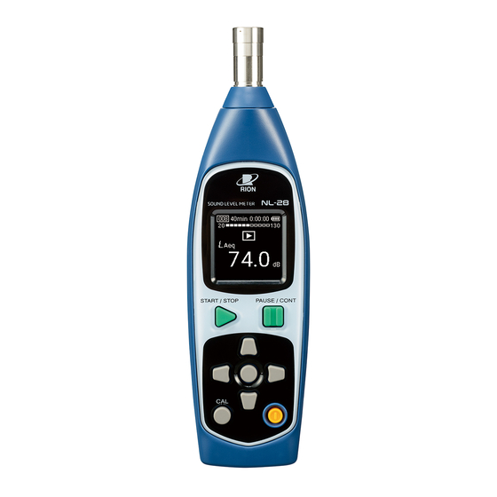
Overview of This Product • NL-28 is a class 2 sound level meter that complies with the Measurement Act, JIS, and IEC. The measurable frequency range is 20 Hz to 8 kHz. • It consists of a main unit including a 1/2-inch microphone and a preamplifier. The main unit is equipped with operation keys and an organic EL display. -
Page 12: Terminology And Notation
Terminology and Notation Correspondence between the notation of measurement value on Class 2 Sound Level Meter NL-28 and the name of measurement value based on standards The following table shows the correspondence between the notation of measurable values on this device and the names of measurement values based on standards (IEC 61672-1 and ISO 1996). - Page 13 Terminology and Notation Correspondence between the notation of measurement value on Class 2 Sound Level Meter NL-28 and the quantifiers in each standard The following table shows the correspondence between the notation of measurable on this device and the quantifiers used in each standard (IEC 61672-1 (JIS C 1509-1) and ISO 1996 (JIS Z 8731)).
-
Page 14: Name And Function Of Each Part
Name and Function of Each Part Front Back Microphone Preamplifier START / STOP PAUSE / CONT Operation panel (Page 15) Name Description The microphone can be separated from the main unit, but the preamplifier is fixed to the Microphone and main unit. - Page 15 Name and Function of Each Part Operation panel START / STOP PAUSE / CONT Name Description Used when starting or ending measurement. START/STOP key Pressing the START/STOP key with the current screen starts measurement. Press again to end the measurement. Used to pause the measurement.
-
Page 16: Turning On The Power
Turning on the Power The device operates on two AA batteries (alkaline batteries or Ni-MH rechargeable batteries). WARNING • If you notice any abnormalities such as excessive heat, smoke, or a burning odor while using the device, immediately remove the batteries, unplug the USB cable connector from the computer, and contact your dealer. •... -
Page 17: Turning On/Off The Power
Turning on the Power Operating time with batteries The operating time with batteries will vary depending on the battery manufacturer and type (model), the usage environment of NL-28, and the measurement conditions. The operating time is approximately as follows. Battery type Operating time (at 23°C) -
Page 18: Reading The Display
Reading the Display Screen transition Power off POWER key Startup screen Power-off Screen Measurement screen Press and hold POWER key (Page 20) Current screen 10min 0:00:05 START/STOP key (Page 19) 10min 0:00:00 67.5 START/STOP key or after Frequency weighting switching measurement time 67.5 has elapsed... -
Page 19: Current Screen
Reading the Display Current screen Note • While the actual display will not look like the one shown in the figures below, the explanation is based on the assumption that all the text are displayed. 10min 0:00:00 AFmax 67.5 Name Description Displays the address of the memory where the data being measured (or the data for Store address... -
Page 20: Measurement Screen
Reading the Display Name Description When a sound level overload condition is detected, the indication is shown for at least 1 second. Overload indication If the calculation contains signal overload data, this indication is shown. This indication remains on the screen until the next measurement is started. -
Page 21: Menu
Menu Menu screen Pressing the center key displays the MENU screen when the current screen is active. Also, pressing the PAUSE/CONT key returns to the current screen. Use the left/right direction keys to switch the setting item display, and press the center key to display the respective setting screen. -
Page 22: Usb Mass Storage
Menu USB mass storage This menu is used to connect the device to a computer. With the device connected to the computer using a USB Type-C cable (Page 43), press the center key when the [USB mass storage] screen is displayed to enable the computer to recognize the device’s internal memory as a removable disk. It is used to check the measurement and calibration history in CSV files and to update the software. - Page 23 Menu • Example of store data screen • Example of calibration history screen...
-
Page 24: Time Weighting Setting
Menu Time weighting setting ⇦ ⇨ This menu is used to set the time weighting. Time weighting Time weighting Center key 〇 Enter ▯ Back 〇 Set ▯ Back The following items can be set using the up/down direction keys. Item Description Sets F (fast). -
Page 25: Battery
Menu Battery This menu is used to set the type of batteries used in the device. Battery Battery Alkaline Center key Ni-MH Alkaline 〇 Enter ▯ Back 〇 Set ▯ Back The following items can be set using the up/down direction keys. Item Description Alkaline... -
Page 26: Calibration
Calibration Calibration can be automatic or manual. Automatic calibration Insert the microphone of the device into the sound calibrator (NC-75/74). If necessary, adjust it so that the time-weighted sound level L (indicated value) display of the device is equal to the sound level in the coupler of the calibrator. - Page 27 Calibration Select [Auto] using the up/down direction keys, Calibration mode then press the center key. Auto Press the PAUSE/CONT key to return to the current Manual screen. 〇 Set 〇 Set ▯ Back ▯ Back Check that the sound calibrator is turned off. Attach the 1/2-inch adapter to the sound calibrator.
- Page 28 Calibration Turn on the sound calibrator. POWER 10min 0:00:00 94.0 START / STOP PAUSE / CONT After inserting the microphone, wait briefly and then START / STOP PAUSE / CONT press the CAL key. Note • Accurate calibration cannot be performed immediately after the microphone is inserted because the air pressure inside the calibrator and microphone has changed.
- Page 29 Calibration Calibration When “Adjust?” appears, press the center key to automatically adjust the indicated value. Auto Adjust? If there is no difference between the indicated value and the calibrated 93.7 value, or if you do not adjust the indicated value, the calibration procedure concludes here.
-
Page 30: Manual Calibration
Calibration Manual calibration For manual calibration, insert the microphone of the device into the sound calibrator (NC-75/74) or the pistonphone (NC-72B/72A). If necessary, adjust it so that the time-weighted sound level L (indicated value) display of the device is equal to the sound level in the coupler of the calibrator. - Page 31 Calibration Check that the sound calibrator or pistonphone is turned off. Attach the 1/2-inch adapter to the sound calibrator or pistonphone coupler. Sound calibrator NC-75 Sound calibrator NC-74 1/2 inch adapter for 1/2 inch adapter for NC-75 NC-74 Coupler Coupler Pistonphone NC-72B Pistonphone NC-72A Coupler...
- Page 32 Calibration 10min 0:00:00 After inserting the microphone, wait a short while and then read the indicated value on the device. Note • Accurate calibration cannot be performed immediately after the 35.4 microphone is inserted because the air pressure inside the calibrator and microphone has changed.
- Page 33 (nominal value is 114 dB) indicated on the calibration slip supplied with the NC-72B/72A, the amount of correction for differences in microphones (-0.03 dB for NL-28), and the static pressure measured with the supplied barometer.
-
Page 34: Checking The Current L P Value
Measurement This section describes how to check the time-weighted sound level L value of the current state and measure the calculated values ( L peak Checking the current L value Check the time-weighted sound level L value in the current screen. Check that the current screen is displayed. - Page 35 Measurement Select the time weighting using the up/down Time weighting direction keys, and press the center key. When measuring according to a standard such as JIS, set the time weighting according to the corresponding standard. Item Description Sets F (fast). 〇...
-
Page 36: Calculated Values Measurement
Measurement Calculated values measurement Measure the calculated values ( L peak Check that the current screen is displayed. Press the center key. START / STOP PAUSE / CONT The menu screen appears. ⇦ ⇨ Press the left/right direction keys to display the [Time weighting] screen, and press the center key. - Page 37 ⇦ ⇨ Measurement Press the left/right direction keys to display the [Measurement time] screen, and press the center key. Measurement time The [Measurement time] screen appears. 10 min 〇 Enter ▯ Back Select the measurement time using the up/down Measurement time direction keys, and press the center key.
- Page 38 Measurement Press the START/STOP key to start measuring. START / STOP PAUSE / CONT At this point, previous measurement values are cleared. 10min 0:00:05 The time-weighted sound level L is displayed in the center of the current screen, with the bar graph updated every 0.1 second and the level values every second.
-
Page 39: Store Operation
Store Operation The device automatically saves the measurement data, including calculated values such as equivalent continuous sound level, and measurement conditions such as time weighting, in the main unit. This section provides details on the saved data. Loading the saved data Read the data stored in the main unit. -
Page 40: Deleting All The Saved Data
Store Operation Deleting all the saved data Deletes all data stored in the main unit. The device does not have a function to individually delete selected data. Check that the current screen is displayed, and press START / STOP PAUSE / CONT the center key. - Page 41 Store Operation Press the START/STOP key and PAUSE/CONT key START / STOP PAUSE / CONT at the same. The confirmation screen appears. Recall Clear all data? ▷ Yes ▯▯ No Press the START/STOP key. START / STOP PAUSE / CONT All stored measurement data will be deleted.
-
Page 42: Connection With Peripheral Devices
Connection with Peripheral Devices 10.1 Attaching the windscreen When measuring noise outdoors in a windy environment or with a ventilation system present, the wind or air can come into contact with the microphone and generate wind noise, which can affect the measurement results. In such cases, wind/air noise can be reduced by installing the supplied windscreen WS-14 to the microphone. -
Page 43: Attaching The Hand Strap
Connection with Peripheral Devices 10.3 Attaching the hand strap When using the device in handheld mode, secure it by attaching the supplied hand strap to prevent any accidental drops. For added security, pass your wrist through the hand strap while using the device. Hand strap attachment part Hand strap 10.4 Computer connection... -
Page 44: Specifications
Specifications IEC 61672-1:2013 class 2 JIS C 1509-1:2017 class 2 JIS C 1516:2020 class 2 Applicable CE Marking standards • EMC Directive Directive 2014/30/EU EN 61326-1:2013 • RoHS Directive Directive 2011/65/EU EN IEC 63000:2018 UKCA Marking, China RoHS, KC Mark At the selected time weighting, the following calculation values can all be measured simultaneously at the frequency weighting A and C. - Page 45 Specifications A reference signal is input using sound calibrator NC-75/NC-74 or pistonphone NC-72B/NC-72A, and the signal input sensitivity is adjusted automatically or manually. Up to 999 calibrations can be managed in the calibration history and saved. NC-75 / NC-74 NC-72B / NC-72A Calibration Calibration signal frequency 1 kHz...
-
Page 46: Microphone
Microphone The Class 2 Sound Level Meter NL-28 is fitted with free-field electret microphone UC-52 that is 1/2 inch in diameter. 12.1 Structure and how it works As shown in the figure below, in general, an electret condenser microphone used for taking measurements consists of five parts: a diaphragm, film, back electrode, insulator, and case. -
Page 47: Frequency Weighting
Frequency Weighting Frequency weighting A and C of the sound level meter are achieved by frequency weighting circuits with electrical characteristics as shown in the following figure. Response (dB) A-weighting C-weighting 100 200 500 1 k 5 k 10 k 20 k 50 k Frequency (Hz) Characteristics of frequency weighting circuits... -
Page 48: Root-Mean-Square Circuit And Time Weighting
This shows that it can be calculated by squaring the instantaneous voltage (e) of the time waveform up to time (T) and taking the square root of the averaged value. NL-28 calculates the root-mean-square value using a digital calculation method. Square... - Page 49 Root-mean-square Circuit and Time Weighting Relationship between time weighting and time constant Time constant Time weighting Rising characteristics Falling characteristics F (fast) 125 ms 125 ms S (slow) The figure below shows the circuit equivalent to the root-mean-square detection with time weighting. τ is the time constant and τ...
-
Page 50: Measurement Function
(t) : A-weighted instantaneous sound pressure at running time t : Reference sound pressure 20 µPa (2 x 10 With NL-28, L is calculated digitally using the following formula: : Number of samples The sampling cycle of NL-28 is 20.8 µs (48,000 samples per second). -
Page 51: L A E (A-Weighted Sound Exposure Level)
(Maximum time-weighted sound level) The maximum time-weighted sound level within the measurement time can be measured. NL-28 holds the maximum value after starting measuring for the sound level at each sampling cycle of 20.8 µs (48,000 samples per second). Therefore, the L value up to that point can be read even while measuring. -
Page 52: Influence Of Background Noise
Influence of Background Noise Background noise refers to the noise in the usage environment when there is no sound that is subject to measurement. As the indicated value of the sound level meter is a mix between the sound to be measured and the background noise, the indicated value may be larger than when only the sound subject to measurement is measured. -
Page 53: Descriptions For Iec 61672-1 (Jis C 1509-1)
Classification of emissions and immunity 9.2.1 a) Group X 5.1.4 Configuration and normal operating conditions 9.2.1 b) Configuration • NL-28 • WS-14 » [Name and Function of Each Part], [Connection with Peripheral Devices] 5.1.5 Conformance class 9.2.1 a) Class 2 5.1.6... - Page 54 No. with Explanation the same content Adjustments at the calibration check frequency 5.2.1 Model of sound calibrator used for calibration 9.2.4 a) NC-75/NC-74 (RION) NC-72B/NC-72A (RION) 5.2.3 Calibration procedure, adjustment values 9.2.4 c) » [Calibration] Corrections to indicated levels 5.3.1...
- Page 55 Descriptions for IEC 61672-1 (JIS C 1509-1) IEC standard JIS standard paragraph Description paragraph No. with Explanation the same content Frequency Weighting 5.5.5 Table of directional index in relation to random 9.3 e) Refer to Tables 9 and 10 incidence characteristics 5.5.8 Design targets and tolerances for optional 9.2.2 k)
- Page 56 Descriptions for IEC 61672-1 (JIS C 1509-1) IEC standard JIS standard paragraph Description paragraph No. with Explanation the same content 5.20 Clock function 5.20.1 Procedure for setting integration time and 9.2.6 f) Integration time clock time » [Measurement time] Clock time »...
- Page 57 Descriptions for IEC 61672-1 (JIS C 1509-1) IEC standard JIS standard paragraph Description paragraph No. with Explanation the same content Power frequency magnetic fields and radio frequency electromagnetic fields 6.6.1 Operation mode and connection state where 9.3 o) Refer to Fig. 5 6.6.3 the effects of power frequency magnetic fields Operation mode: Normal operation...
- Page 58 Descriptions for IEC 61672-1 (JIS C 1509-1) IEC standard JIS standard paragraph Description paragraph No. with Explanation the same content Characteristics and operations of each 9.2.1 e) 5.1.18 Refer to 5.1.18 independent channel 9.2.1 f) Influence of mechanical vibration and how Refer to 6.7 to reduce it 9.2.2...
- Page 59 Descriptions for IEC 61672-1 (JIS C 1509-1) IEC standard JIS standard paragraph Description paragraph No. with Explanation the same content 9.2.5 c) Typical windscreen influence 5.3.3.1 Refer to 5.3.3.1 9.2.5 d) Correction value for multi-frequency sound 5.3.5.1 Refer to 5.3.5.1 calibrator 5.3.5.3 Refer to 5.3.5.3...
- Page 60 Descriptions for IEC 61672-1 (JIS C 1509-1) IEC standard JIS standard paragraph Description paragraph No. with Explanation the same content 9.2.8 Influence of changes in environmental conditions 9.2.8 a) Components that operate only under specific 6.3.2 Refer to 6.3.2 environmental conditions 9.2.8 b) I n fl u e n c e o f e l e c t ro s ta t i c d i s c h a rg e 6.5.2...
-
Page 61: Free-Field Characteristics
Descriptions for IEC 61672-1 (JIS C 1509-1) 17.1 Free-field characteristics Table 1. NL-28 free-field characteristics Without windscreen WS-14 installed Microphone Free-field Response Influence of Case Reflection Nominal Exact NL-28 (dB) (dB) Frequency Frequency Electrical UC-52 Expanded Expanded (Hz) (Hz) Response (dB) - Page 62 Descriptions for IEC 61672-1 (JIS C 1509-1) Microphone Free-field Response Influence of Case Reflection Nominal Exact NL-28 (dB) (dB) Frequency Frequency Electrical UC-52 Expanded Expanded (Hz) (Hz) Response (dB) NL-28 (NL-28) Uncertainty Uncertainty 4000 3981.1 -0.2 0.20 4250 4217.0 -0.3 0.20...
- Page 63 Descriptions for IEC 61672-1 (JIS C 1509-1) With windscreen WS-14 installed Microphone Free-field Influence of Case Influence of Windscreen NL-28 Nominal Exact Response (dB) Reflection (dB) (dB) Electrical Frequency Frequency Response UC-52 Expanded Expanded WS-14 Expanded (Hz) (Hz) NL-28 (dB)
- Page 64 Descriptions for IEC 61672-1 (JIS C 1509-1) Microphone Free-field Influence of Case Influence of Windscreen NL-28 Nominal Exact Response (dB) Reflection (dB) (dB) Electrical Frequency Frequency Response UC-52 Expanded Expanded WS-14 Expanded (Hz) (Hz) NL-28 (dB) (NL-28) Uncertainty Uncertainty Effect...
-
Page 65: Reference Incident Direction And Position Of Reference Point
Descriptions for IEC 61672-1 (JIS C 1509-1) 17.2 Reference incident direction and position of reference point Reference incident direction Position of reference point Center point on diaphragm surface Fig. 1. Reference incident direction and position of reference point 17.3 Microphone frequency response The frequency response of a free-field microphone is represented by the response to the sound waves from the reference incident direction in a free-field. -
Page 66: Acoustic Influence Of Case
Descriptions for IEC 61672-1 (JIS C 1509-1) 17.4 Acoustic influence of case NL-28 is designed to minimize the influence of case-related acoustic reflections on measurements. The acoustic influence from the case is shown below. Response (dB) 100k Frequency (Hz) Fig. 3. Acoustic influence of case 17.5 Effects of windscreen WS-14... -
Page 67: Electromagnetic Compatibility (Emc)
Descriptions for IEC 61672-1 (JIS C 1509-1) 17.6 Electromagnetic compatibility (EMC) The following figure shows the immunity test conditions (NL-28 direction, operation mode and connection state) against power frequency magnetic fields and radio frequency electromagnetic fields. Under these conditions, the effects of exposure to power frequency magnetic field and radio frequency electromagnetic field are at their largest. -
Page 68: Microphone Free-Field Correction Amount
Descriptions for IEC 61672-1 (JIS C 1509-1) 17.7 Microphone free-field correction amount Table 3. Free-field correction amount for microphones when calibrating sound pressure using a sound calibrator UC-52 (NL-28) Nominal frequency (Hz) Exact frequency (Hz) Expanded uncertainty (dB) correction amount (dB) 31.5... -
Page 69: Upper And Lower Limits Of Linear Operating Range For Sound Pressure Level
Descriptions for IEC 61672-1 (JIS C 1509-1) 17.8 Upper and lower limits of linear operating range for sound pressure level Table 4. Upper and lower limits of linear operating range for sound pressure level A-weighting 31.5 Hz 1 kHz 4 kHz 8 kHz Upper limit 97.0... -
Page 70: Directional Characteristics
(0°) and the measurement value of any incident angle θ. The electret condenser microphone used in NL-28 is a pressure-type microphone, so it is primarily omnidirectional. However, at higher frequencies, it becomes directional due to the effects of structure-related diffraction and dents. - Page 71 Descriptions for IEC 61672-1 (JIS C 1509-1) Table 5. Directional characteristics of NL-28 (horizontal direction) Nominal frequency / exact frequency (Hz) Angle (degrees) 250/251.19 315/316.23 400/398.11 500/501.19 630/630.96 800/794.33 1000/1000.0 1250/1258.9 0.00 0.00 0.00 0.00 0.00 0.00 0.00 0.00 0°...
- Page 72 Descriptions for IEC 61672-1 (JIS C 1509-1) Nominal frequency / exact frequency (Hz) Angle (degrees) 1600/1584.9 2000/1995.3 2240/2238.7 2500/2511.9 2800/2818.4 3150/3162.3 3550/3548.1 4000/3981.1 0.00 0.00 0.00 0.00 0.00 0° 0.00 0.00 0.00 10° -0.01 0.01 0.00 -0.05 0.00 -0.02 0.04 -0.04 -0.04 0.06...
- Page 73 Descriptions for IEC 61672-1 (JIS C 1509-1) Nominal frequency / exact frequency (Hz) Angle (degrees) 4500/4466.8 5000/5011.9 5600/5623.4 6300/6309.6 7100/7079.5 8000/7943.3 0° 0.00 0.00 0.00 0.00 0.00 0.00 10° -0.11 -0.14 -0.06 -0.02 0.05 -0.04 20° -0.16 -0.38 -0.16 -0.09 0.09 -0.20 30°...
- Page 74 100° 270° 90° 250° 110° 250 Hz 240° 120° 1 kHz 180° 230° 130° 2 kHz 220° 140° 4 kHz 210° 150° Sound incident direction 8 kHz 200° 160° 190° 170° 180° Fig. 7. Directional characteristics of NL-28 (vertical direction)
- Page 75 Descriptions for IEC 61672-1 (JIS C 1509-1) Table 6. Directional characteristics of NL-28 (vertical direction) Nominal frequency / exact frequency (Hz) Angle (degrees) 250/251.19 315/316.23 400/398.11 500/501.19 630/630.96 800/794.33 1000/1000.0 1250/1258.9 0.00 0.00 0.00 0.00 0.00 0.00 0.00 0.00 0°...
- Page 76 Descriptions for IEC 61672-1 (JIS C 1509-1) Nominal frequency / exact frequency (Hz) Angle (degrees) 1600/1584.9 2000/1995.3 2240/2238.7 2500/2511.9 2800/2818.4 3150/3162.3 3550/3548.1 4000/3981.1 0° 0.00 0.00 0.00 0.00 0.00 0.00 0.00 0.00 10° -0.03 0.05 -0.05 -0.09 0.04 0.01 -0.06 -0.13 20°...
- Page 77 Descriptions for IEC 61672-1 (JIS C 1509-1) Nominal frequency / exact frequency (Hz) Angle (degrees) 4500/4466.8 5000/5011.9 5600/5623.4 6300/6309.6 7100/7079.5 8000/7943.3 0.00 0.00 0.00 0° 0.00 0.00 0.00 10° -0.05 -0.16 -0.11 0.04 -0.01 -0.05 -0.51 0.03 -0.17 20° -0.05 -0.27 -0.01 30°...
- Page 78 270° 90° 250 Hz 240° 120° 1 kHz 230° 130° 180° 2 kHz 220° 140° 4 kHz 210° 150° 200° 160° 8 kHz 190° 170° Sound incident direction 180° Fig. 8. Directional characteristics of NL-28 with WS-14 attached (horizontal direction)
- Page 79 Descriptions for IEC 61672-1 (JIS C 1509-1) Table 7. Directional characteristics of NL-28 with WS-14 attached (horizontal direction) Nominal frequency / exact frequency (Hz) Angle (degrees) 250/251.19 315/316.23 400/398.11 500/501.19 630/630.96 800/794.33 1000/1000.0 1250/1258.9 0.00 0.00 0.00 0.00 0.00 0.00 0.00...
- Page 80 Descriptions for IEC 61672-1 (JIS C 1509-1) Nominal frequency / exact frequency (Hz) Angle (degrees) 1600/1584.9 2000/1995.3 2240/2238.7 2500/2511.9 2800/2818.4 3150/3162.3 3550/3548.1 4000/3981.1 0° 0.00 0.00 0.00 0.00 0.00 0.00 0.00 0.00 10° -0.01 0.07 -0.02 0.02 0.03 -0.04 0.00 -0.06 20°...
- Page 81 Descriptions for IEC 61672-1 (JIS C 1509-1) Nominal frequency / exact frequency (Hz) Angle (degrees) 4500/4466.8 5000/5011.9 5600/5623.4 6300/6309.6 7100/7079.5 8000/7943.3 0° 0.00 0.00 0.00 0.00 0.00 0.00 10° 0.08 -0.04 0.00 -0.05 -0.01 -0.06 20° -0.23 -0.41 -0.16 -0.04 0.05 -0.31 30°...
- Page 82 270° 90° 250 Hz 240° 120° 1 kHz 230° 130° 180° 2 kHz 220° 140° 4 kHz 210° 150° 200° 160° 8 kHz 190° 170° Sound incident direction 180° Fig. 9. Directional characteristics of NL-28 with WS-14 attached (vertical direction)
- Page 83 Descriptions for IEC 61672-1 (JIS C 1509-1) Table 8. Directional characteristics of NL-28 with WS-14 attached (vertical direction) Nominal frequency / exact frequency (Hz) Angle (degrees) 250/251.19 315/316.23 400/398.11 500/501.19 630/630.96 800/794.33 1000/1000.0 1250/1258.9 0.00 0.00 0.00 0.00 0.00 0.00 0.00...
- Page 84 Descriptions for IEC 61672-1 (JIS C 1509-1) Nominal frequency / exact frequency (Hz) Angle (degrees) 1600/1584.9 2000/1995.3 2240/2238.7 2500/2511.9 2800/2818.4 3150/3162.3 3550/3548.1 4000/3981.1 0° 0.00 0.00 0.00 0.00 0.00 0.00 0.00 0.00 10° -0.12 -0.04 -0.04 -0.14 0.02 -0.04 0.07 -0.11 20°...
- Page 85 Descriptions for IEC 61672-1 (JIS C 1509-1) Nominal frequency / exact frequency (Hz) Angle (degrees) 4500/4466.8 5000/5011.9 5600/5623.4 6300/6309.6 7100/7079.5 8000/7943.3 0° 0.00 0.00 0.00 0.00 0.00 0.00 10° -0.30 -0.26 -0.14 -0.01 -0.05 -0.13 20° -0.27 -0.50 -0.27 0.01 -0.07 -0.29 30°...
-
Page 86: Random Incidence Response
The high-frequency response is lower in a diffuse field than in a free-field. Response (dB) 10 k 100 k Frequency (Hz) Fig. 10. NL-28 random incidence response Table 9. NL-28 random incidence response Nominal Exact Random incidence Nominal Exact... - Page 87 -� -� -�� ��� � k �� k ��� k Frequency (Hz) Fig. 11. Random incidence response of NL-28 with WS-14 attached Table 10. Random incidence response of NL-28 with WS-14 attached Nominal Exact Random incidence Nominal Exact Random incidence...
- Page 88 • QR code is a registered trademark of DENSO WAVE Incorporated. • All company names and product names mentioned in this manual are trademarks or registered trademarks of their respective owners. https://www.rion.co.jp/english/ 3-20-41 Higashimotomachi, Kokubunji, Tokyo 185-8533, Japan No. 67572...
Need help?
Do you have a question about the NL-28 and is the answer not in the manual?
Questions and answers