Sign In
Upload
Manuals
Brands
INVT Manuals
Controller
SV-DB100 Series
INVT SV-DB100 Series Manuals
Manuals and User Guides for INVT SV-DB100 Series. We have
2
INVT SV-DB100 Series manuals available for free PDF download: Operation Manual
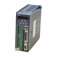
INVT SV-DB100 Series Operation Manual (171 pages)
AC Servo Drives
Brand:
INVT
| Category:
Controller
| Size: 6.84 MB
Table of Contents
Table of Contents
6
Content
10
General Technical Specifications
10
Illustration of the Nameplate
13
Nameplate of the Servo Drive
13
Power Specification
14
External Dimensions and Installations Sizes of the Servo Drive
15
Illustrations of Every Parts of the Servo Drive
15
1 General
10
2 Unpacking Inspection
17
3 Installation
18
Environmental Requirement
18
Temperature
18
Relative Humidity
18
Altitude
18
Other Environment Requirements
19
Installation of the Servo Drive
19
Installation
19
Installation Direction and Spacing
20
Avoid Intrusion of Foreign Objects
21
4 Signal and Wiring
22
System Configuration
23
Connection Diagram of the Servo Drive and External Equipment
23
Cable Diameter Selection
23
EMI Filter Selection
24
Braking Resistor Selection
25
Wiring of the Main Circuit (Plug X1 and X2)
26
Overview
26
Wiring Diagram of Single Phase 230V Power Input
27
Wiring Diagram of Three-Phase 230V Power Input
28
Wiring Diagram of Three-Phase 400V Power Input
29
Wiring of the Encoder (Plug CN2)
30
Overview
30
CN2 Pin Arrangement and Signal Definition of the Servo Drive
30
Connection with the PC or HOST (CN3 Plug)
31
I/O Signal Wiring (CN1 Connector)
32
Overview
32
CN1 Pin Arrangement and Signal Explanation
33
Standard Wiring of the Position Control Mode
43
Standard Wiring of the Speed Control Mode
44
Standard Wiring of the Torque Control Mode
45
Detailed Instruction of the Input and Output of CN1
46
Wiring of the Electromagnetic Brake
52
5 Running and Operation
53
Running
53
First Powering on
53
Self-Test before Running of the Servo
54
Parameter Setting before Running the Servo
54
Trial Jogging
55
Running at the Position Control Mode
55
Running at the Speed Control Mode
56
Running at the Torque Control Mode
57
Parameter Setting before Running the Servo
58
Servo Enabling
59
Coast to Stop / DEC to Stop of the Servo
59
Sequence Diagram
61
Display and Operation
66
Display
66
State Monitoring Mode
67
Parameter Setting
69
Auxiliary Functions
75
Alarm Display
76
Alarm Clearance
77
6 Detailed Parameter Description
78
Basic Parameters (FP0 Group Parameters)
78
Basic Control
78
Position Control
85
Speed and Torque Control
88
Self-Turning Control Parameters (FP1 Group Parameters)
97
Inertia Identification(Automatic Gain)
97
Adaptive Vibration Control
99
Motor Control Parameters (FP2 Group Parameters)
101
Gain
101
Gain Switching
103
Special Motor Control
105
I/O Management Parameters (FP3 Group Parameters)
105
1Digital Input
105
Analog Input / Output Adjustment
106
Switch Input / Output Settings
109
Extension and Application (FP4 Group Parameters)
112
Communication Setting
112
Alarm Threshold Setting
115
Factory Parameters (FP9 Group Parameters)
116
State Monitoring
117
7 Gain Adjustment
123
General Method for Adjusting Parameters
123
Adjustment of the Gain of the Position Loop
125
Adjustment of the Gain of the Speed Loop
126
Adjustment of the Gain of the Torque Loop
128
Suppression of Mechanical Resonance
129
Gain Switching Function
130
8 Communication Function
131
General
131
Topological Structure
131
Communication with Single Set
131
Communication with Multiple Sets
131
Communication Protocol
132
Protocol Content
132
Protocol Instructions
132
Communication Protocol Format
133
Command Code and the Communication Data Instructions
134
Error Checkout of the Communication Frame
140
Address Definition of Communication Data
141
Fault Responses
143
9 Fault Processing
145
Meanings of the Fault Alarm Codes and Countermeasures
145
Meanings of the Warning Codes
148
Appendix A List of Function Parameters
149
Appendix B Signal Arrangement Diagram
156
CN1 Pin Signal Arrangement
156
CN2 Pin Signal Arrangement
156
CN3 Pin Signal Arrangement
157
Appendix C Plug Signal of Servo Motor
158
Plug of the Motor
158
Below and Including 750
158
Above 750W
158
Plug of Encoder Wire
158
Below and Including 750W
158
Above 750W
159
Appendix D Wiring Examples
161
Connection with Panasonic FPG-C32T
161
Connection with Panasonic FP2-PP22 (AFP2434)
162
Connection with Panasonic FP2-PP2 (AFP2430)
163
Connection with Yokogawa PLC F3YP14-ON/F3YP18-ON
164
Connection with Yokogawa PLC F3NC32-ON/F3NC34-ON
165
Connection with Omron CS1W-NC133/233/433
166
Connection with Omron CJ1W-NC133/233/433
167
Connection with Mitsubishi QD75D1
168
Connection with Mitsubishi FX-1PG
169
Connection with Mitsubishi FX2N-1PG
170
Advertisement
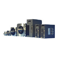
INVT SV-DB100 Series Operation Manual (172 pages)
AC servo drives
Brand:
INVT
| Category:
Servo Drives
| Size: 65.65 MB
Table of Contents
Safety Precautions
3
Warnings
3
Content
6
General
10
General Technical Specifications
10
Standard Specifications of Servo Drive
10
Nameplate of the Servo Drive
13
Illustration of the Nameplate
13
Meanings of the Model
13
Power Specification
14
Illustrations of Every Parts of the Servo Drive
15
External Dimensions and Installations Sizes of the Servo Drive
16
Unpacking Inspection
17
Installation
18
Environmental Requirement
18
Temperature
18
Altitude
18
Installation of the Servo Drive
19
Other Environment Requirements
19
Mounting Holes of the Servo Drive
19
Installation Direction and Spacing
20
Installation of Single Servo Drive
20
Installation of Several Servo Drives
21
Signal and Wiring
22
System Configuration
23
Cable Diameter Selection
24
EMI Filter Selection
24
Braking Resistor Selection
25
Wiring of the Main Circuit
26
Wiring of the Encoder
30
CN2 Pin Arrangement and Signal Definition of the Servo Drive
30
Connection with the PC or HOSE
31
I/O Signal Wiring
32
Power Signal
34
Pulse Input Signals and Their Functions
40
Standard Wiring of the Position Control Mode
43
Standard Wiring of the Speed Control Mode
44
Standard Wiring of the Torque Control Mode
45
Wiring of ON-OFF Input Circuit
46
Wiring of the Pulse Input Circuit
46
Running
53
First Powering on
53
Self Test Running of the Servo
54
Parameter Setting before Running the Servo
54
Checking after Powering on
54
Trial Jogging
55
Running at the Position Control Mode
55
Running at the Speed Control Mode
56
Running at the Torque Control Mode
57
Servo Enabling
59
Coast to Stop / DEC to Stop of the Servo
59
Sequence Diagram
61
Servo off Sequence in a Locked State
63
Servo off Sequence in Running State
64
Sequence of Fault Alarm
65
Display and Operation
66
Function Meaning
68
Parameter List
70
Auxiliary Functions
75
Operation Flowchart for Jogging Trial
75
Alarm Display
76
Alarm Clearance
77
Detailed Parameter Description
78
Basic Parameters
78
Basic Control
78
Position Control
85
Speed and Torque Control
88
Self-Turning Control Parameters
97
Inertia Identification
97
Motor Control Parameters
101
Gain
101
Gain Switching
103
Special Motor Control
105
I/O Management Parameters
105
Digital Input
105
Analog Input/Output Adjustment
106
Extension and Application
112
Communication Setting
112
Gain Adjustment
123
General Method for Adjusting Parameters
123
Parameters Are Appropriate
124
Gain of the Speed Loop Is Relatively High
124
Gain of the Speed Loop Is too Low
124
Adjustment of the Gain of the Speed Loop
125
Block Diagram of Speed Control
127
Adjustment of the Gain of the Torque Loop
128
Suppression of Mechanical Resonance
129
Gain Switching Function
130
Schematic Diagram of Gain Switching
130
Communication Function
131
Topological Structure
131
Communication with Single Set
131
Communication Protocol
132
Protocol Content
132
Protocol Instructions
132
Communication Protocol Format
133
ASCII Mode
133
RTU Mode
133
Error Checkout of the Communication Frame
140
List of Function Parameters
149
Signal Arrangement Diagram
156
CN1 Pin Signal Arrangement
156
CN2 Pin Signal Arrangement
156
CN3 Pin Signal Arrangement
157
Plug Signal of Servo Motor
158
Plug of the Motor
158
Plug of Encoder Wire
158
Wiring Examples
161
Advertisement
Related Products
INVT SV-DB100-0R2-2
INVT SV-DB100-1R0-2-1R
INVT SV-DB100-0R7-2
INVT SV-DB100-1R0-2
INVT SV-DB100-1R5-2
INVT SV-DB100-2R0-2
INVT SV-DB100-1R5-4
INVT SV-DB100-1R0-4
INVT SV-DB100-2R0-4
INVT SV-DB100-3R0-4
INVT Categories
Inverter
DC Drives
Servo Drives
Controller
I/O Systems
More INVT Manuals
Login
Sign In
OR
Sign in with Facebook
Sign in with Google
Upload manual
Upload from disk
Upload from URL