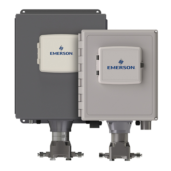
Emerson FB2100 Field Replacement Manual
Flow computer cpu enclosure and electronics replacement
Hide thumbs
Also See for FB2100:
- Instruction manual (126 pages) ,
- Safe use instructions (52 pages) ,
- Quick start manual (42 pages)
Table of Contents
Advertisement
Quick Links
Advertisement
Table of Contents

Related Manuals for Emerson FB2100


Summary of Contents for Emerson FB2100
- Page 1 FB2100/FB2200 Flow Computer CPU Enclosure and Electronics Field Replacement Guide D301803X012 June 2018 FB2100/FB2200 Flow Computer CPU Enclosure and Electronics Field Replacement Guide Note: See page 2 for kit/part numbers. Remote Automation Solutions...
- Page 2 Emerson office. You can also receive the same quality training via our live, interactive Emerson Virtual Classroom and save on travel costs. For our complete schedule and further...
-
Page 3: Table Of Contents
FB2100/FB2200 Flow Computer CPU Enclosure and Electronics Field Replacement Guide D301803X012 June 2018 Replacing the CPU Enclosure, Electronics You can replace the CPU enclosure and its individual boards in the field provided that the replacement has the exact same part number and version. - Page 4 FB2100/FB2200 Flow Computer CPU Enclosure and Electronics Field Replacement Guide D301803X012 June 2018 Note Refer to the table below for the correct field replacement part numbers. Item Field Replacement Kit Part Number CPU Board 621678-01-0 Optional 6-Channel Expansion I/O Board...
-
Page 5: Removing/Restoring Main Power
FB2100/FB2200 Flow Computer CPU Enclosure and Electronics Field Replacement Guide D301803X012 June 2018 Because some of these procedures involve removing small parts such as screws and standoffs, we recommend you bring a container for holding small parts. CPU enclosure (bottom) -
Page 6: Removing Main Power
FB2100/FB2200 Flow Computer CPU Enclosure and Electronics Field Replacement Guide D301803X012 June 2018 Removing Main Power Before you begin any of these procedures, you must remove main power. Terminal block TB2 (pins 1,3,5,7) includes connections for DC power (DCIN+, DCIN-) and battery/ solar power (BATT+, BATT-). -
Page 7: Restoring Main Power
FB2100/FB2200 Flow Computer CPU Enclosure and Electronics Field Replacement Guide D301803X012 June 2018 2. Unplug TB2 (pins 1,3,5,7) to deactivate DC or battery/solar power. This shuts OFF power from either an external power supply or the internal battery pack/solar panel. -
Page 8: Replacing The Hmi Module
FB2100/FB2200 Flow Computer CPU Enclosure and Electronics Field Replacement Guide D301803X012 June 2018 Removing/Replacing the HMI Module The HMI module attaches to the outside of the CPU enclosure cover. Removing the HMI Module Use a #1 Phillips-head screwdriver to loosen the four captive fastening screws that attach the HMI module to the CPU enclosure cover. -
Page 9: Replacing The Hmi Module
B, C, D Flow Computer CPU Box Option 1 Field Installed Accessory Kit Part No. 621673- 01-0 for use with UL Listed Model Series FB2100 and FB2200. Flow Computer CPU Box Option 2 Field Installed Accessory Kit Part No. 621674- 01-0 for use with UL Listed Model Series FB2100 and FB2200. - Page 10 FB2100/FB2200 Flow Computer CPU Enclosure and Electronics Field Replacement Guide D301803X012 June 2018 2. Disconnect the cable between the CPU enclosure and the sensor. See Disconnecting the Cable Between the CPU Enclosure and the Sensor on page 7. 3. Use a #2 Phillips-head screwdriver to loosen the four captive fastening screws that...
-
Page 11: Re-Attaching The Cpu Enclosure To The Battery Compartment
FB2100/FB2200 Flow Computer CPU Enclosure and Electronics Field Replacement Guide D301803X012 June 2018 4. Gently pull the CPU enclosure out of the flow computer enclosure. Re-attaching the CPU Enclosure to the Battery Compartment 1. Line up the CPU enclosure's captive fastening screws with their matching holes on the other assemblies and battery compartment. -
Page 12: Removing/Replacing The Cpu Enclosure Cover (Top)
Division 2, Groups A, B, C, D Flow Computer CPU Enclosure Cover (Top) Field Installed Accessory Kit Part No. 399264-01-0 for use with UL Listed Model Series FB2100 and FB2200. You remove the CPU enclosure cover to gain access to the inside of the CPU enclosure, to perform a field replacement, or if you need to replace the CPU enclosure cover itself. -
Page 13: Replacing The Cpu Enclosure Cover (Top)
FB2100/FB2200 Flow Computer CPU Enclosure and Electronics Field Replacement Guide D301803X012 June 2018 5. Pull off the CPU enclosure cover to reveal the inside of the CPU enclosure. Replacing the CPU Enclosure Cover (Top) 1. Press the CPU enclosure cover (whether the original cover or a new replacement cover) against the CPU enclosure. -
Page 14: Removing/Replacing The Adapter Board
Groups A, B, C, D Flow Computer Adapter Board Field Installed Accessory Kit Part No. 400209010- KIT for use with UL Listed Model Series FB2100 and FB2200. The adapter board resides inside the CPU enclosure. It provides a connection through a slot in the CPU enclosure cover to the HMI module. - Page 15 FB2100/FB2200 Flow Computer CPU Enclosure and Electronics Field Replacement Guide D301803X012 June 2018 4. Remove the CPU enclosure cover. See Removing the CPU Enclosure Cover (Top) on page 10. 5. Remove the two CPU board screws closest to the adapter board. This allows some free movement of the CPU board when you remove the adapter board.
-
Page 16: Replacing The Adapter Board
FB2100/FB2200 Flow Computer CPU Enclosure and Electronics Field Replacement Guide D301803X012 June 2018 Replacing the Adapter Board 1. Gently slide the adapter board onto the CPU board connector. 2. Once on the connector, carefully lift it just enough so it moves to sit inside the four plastic tabs on the bottom of the CPU enclosure. - Page 17 FB2100/FB2200 Flow Computer CPU Enclosure and Electronics Field Replacement Guide D301803X012 June 2018 6. Use a #1 Phillips-head screwdriver to remove the screws that hold down the CPU board. Save the screws. If you have the 6-channel expansion I/O board installed, there are 6 screws, if you do not, there are 4 screws.
-
Page 18: Replacing The Cpu Board
FB2100/FB2200 Flow Computer CPU Enclosure and Electronics Field Replacement Guide D301803X012 June 2018 Replacing the CPU Board 1. Gently slide the CPU board into its connector on the connectivity board. Make sure it is firmly in place. 2. Attach the CPU board using the screws saved from when you removed it but leave the two screws nearest the adapter board off. -
Page 19: Removing/Replacing The Optional 6-Channel Expansion I/O Board
Class I, Division 2, Groups A, B, C, D Flow Computer 6-Channel Expansion I/O Board Field Installed Accessory Kit Part No. 400215010-KIT for use with UL Listed Model Series FB2100 and FB2200. The optional 6-channel expansion I/O board resides inside the CPU enclosure. You... -
Page 20: Removing The Optional 6-Channel Expansion I/O Board
FB2100/FB2200 Flow Computer CPU Enclosure and Electronics Field Replacement Guide D301803X012 June 2018 Removing the Optional 6-Channel Expansion I/O Board 1. Remove the HMI module. See Removing the HMI Module on page 6. 2. Disconnect the cable between the CPU enclosure and the sensor. See Disconnecting the Cable Between the CPU Enclosure and the Sensor on page 7. -
Page 21: Removing/Replacing The Connectivity Board
Groups A, B, C, D Flow Computer Connectivity Board Field Installed Accessory Kit Part No. 400211010-KIT for use with UL Listed Model Series FB2100 and FB2200. The connectivity board provides connections to the CPU board as well as the optional 6-channel expansion I/O board inside the CPU enclosure. -
Page 22: Removing The Connectivity Board
FB2100/FB2200 Flow Computer CPU Enclosure and Electronics Field Replacement Guide D301803X012 June 2018 Connectivity board connectors that go through the bottom of the CPU enclosure to mate with the Termination I/O board You would remove/replace the connectivity board if it fails, or as a step in the field replacement of the CPU enclosure (bottom). -
Page 23: Replacing The Connectivity Board
FB2100/FB2200 Flow Computer CPU Enclosure and Electronics Field Replacement Guide D301803X012 June 2018 8. Slide the connectivity board out of the CPU enclosure and set it aside. Replacing the Connectivity Board 1. Slide the connectivity board into the bottom of the CPU enclosure. The Ethernet port must fit into its matching opening on the side of the enclosure. -
Page 24: Removing/Replacing The Cpu Enclosure (Bottom)
Division 2, Groups A, B, C, D Flow Computer Enclosure Box (Bottom) Field Installed Accessory Kit Part No. 399260-01-0 for use with UL Listed Model Series FB2100 and FB2200. You only replace the CPU enclosure (bottom) if the original box is damaged. -
Page 25: Replacing The Cpu Enclosure (Bottom)
FB2100/FB2200 Flow Computer CPU Enclosure and Electronics Field Replacement Guide D301803X012 June 2018 Replacing the CPU Enclosure (Bottom) 1. Slide the connectivity board into the bottom of the new CPU enclosure. The Ethernet port must fit into its matching opening on the side of the enclosure. - Page 26 Emerson Automation Solutions Remote Automation Solutions Emerson FZE P.O. Box 17033 © 2018 Remote Automation Solutions, a business unit of Emerson Automation Solutions. All Jebel Ali Free Zone – South 2 rights reserved. Dubai U.A.E. This publication is for informational purposes only. While every effort has been made to ensure...
Need help?
Do you have a question about the FB2100 and is the answer not in the manual?
Questions and answers