
Related Manuals for Grundfos FireSAFE+


Summary of Contents for Grundfos FireSAFE+
- Page 1 GRUNDFOS INSTRUCTIONS FireSAFE+ Grundfos firefighting systems, domestic range • Safety Instructions • Installation & Operating Instructions • CE & UKCA Declarations of Conformity P a g e...
-
Page 2: Table Of Contents
Table of Contents 1.0 Safety Instructions 2.0 When and how to use the FireSAFE+ 4.8 Break tanks and mains water connection Installation & Operating instructions 4.9 Installation - General requirements 2.1 Symbols used in this document 4.10 Wall fixing dimensions 2.2 Scope of these Instructions 4.11 Operating conditions 2.3 Product Identification... -
Page 3: Safety Instructions
1.0 Safety Instructions Original Safety Instructions These safety instructions give an overview of the safety precautions to be taken in connection with any work on this product. Observe these safety instructions during handling, installation, operation, maintenance, service, and repair of this product. These safety instructions are an explanatory section, and all safety instructions will appear again in the relevant sections of the installation and operating instructions. - Page 4 Hazard: Electrical installation DANGER - Electric shock. Death or serious personal injury. If requiring repair consult Grundfos, details on back page. DANGER - Electric shock. Death or serious personal injury. - Check that the supply voltage and frequency correspond to the values stated on the nameplate.
- Page 5 DANGER - Electric shock Death or serious personal injury - If the control panel is cracked, perforated, or damaged, immediately isolate, and contact Grundfos, details on back page, to arrange a repair/replacement. Hazard: Repair/Servicing the product DANGER - Electric shock Death or serious personal injury - Switch off the power supply to the unit.
-
Page 6: When And How To Use The Firesafe+ Installation & Operating Instructions
For Technical Information consult the FireSAFE+ Datasheet For CM Pump specific information please consult the CM Installation and Operating manual and datasheets. All the above documents can also be found on the Grundfos Product Centre website at: www.grundfos.com/uk P a g e... -
Page 7: Product Identification
We also recommend that a filtration component (Y-strainer or similar) is used to protect the Solenoid valve. This is available in the Cooling line accessory supplied by Grundfos. Additionally, a Battery Backup module to sustain the buzzer alarm in the event of extended local power loss is available from RS. -
Page 8: Key Product Components
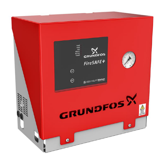
2.5 Key product components Access requires a TX30 The FireSAFE+ unit is contained within a two-piece steel cabinet. security screwdriver The following components are integrated within the FireSAFE+ product Images 1-4 Identification Component Description Controller Membrane, LED’s and Buttons Pressure Gauge Security Screw –... - Page 9 Pump (Item 6, Images 1-4) From the Grundfos high quality CM centrifugal horizontal multi-stage range. Choice of seven sizes available within the FireSAFE+ range. Refer to Pump data sheet for more info. Pressure gauge (Item 2, Images 1-4) Providing visual indication of the system pressure and for fine-tuning the pressure switch setting.
-
Page 10: Installation And Operating Instructions
Original Installation and Operating Instructions 3.1 Sequence of Operation The Grundfos FireSAFE+ supplies water, usually from a storage tank, via a riser system within the building to a system of sprinkler heads. Should the pressure in the sprinkler system decay, through minor leakage, then the FireSAFE+ unit will detect this pressure drop, via inbuilt pressure switches and run the pump to re- pressurize the system (Jockey Mode). -
Page 11: Modes Of Operation
3.2 Modes of Operation The FireSAFE+ unit has been specifically designed by Grundfos to assist system designers and installers with complying to the BS, EN and LPS standards, integrating key system signals, monitoring system conditions and to operate automatically. The FireSAFE+ controller has the following modes of Operation: o Jockey Mode - Pressure maintenance o Possible Fire Mode –... -
Page 12: Integration Of Signals
Refer to section 3.5 3.3 Integration of Signals. The FireSAFE+ unit has been specifically designed with the ability to power and relay digital signals. The signals could be from any source, but Grundfos suggest the following important signals are used: o Flow Switch... -
Page 13: Mains Power Monitoring / Controller Internal Fuse Monitoring
3.4 Mains power monitoring / Controller internal fuse monitoring On the application of mains electrical power, the Power LED on the controller front panel illuminates and the Fault output moves to its healthy position. Upon failure of the mains power or the controller’s internal fuse the LED extinguishes, the Fault relay moves to its unhealthy position and after more than 2 hours without power the internal buzzer activates for 1 second every 30 minutes. -
Page 14: Led Operation
3.6 LED Operation Function PUMP ON = Pump running FAULT ON, Two Flashes = Auto Test Failure ON, Three Flashes = Low Water ON, Four Flashes = Pressure Switch 1 Failure ON, Five Flashes = Pressure Switch 2 Failure ON, Six Flashes = Excessive Operation ON, Nine Flashes = Cooling line Failure ON, Ten Flashes = Possible Fire Mode FIRE! -
Page 15: Programming Settings
• Remove USB memory stick device, replace the Red plug, re-assemble the Front cover. Programming settings A text file called settings.txt, available from Grundfos, can be used to customize the unit values with the aid of a laptop before saving these to the USB device. Then performing the process described above. -
Page 16: Extracting Data
3.8 Extracting Data logs Perform the above process. The USB memory device will now have 4 text files on. • Autotest Log (records results of all Autotest cycles, Auto or Manually initiated) • Fault (records the number and name of the fault and when it occurred) •... -
Page 17: Factory Settings
Flow Switch Delay:-1; 0 to 25 Seconds Pressure Switch Delay:-3; 0 to 10 Seconds Fire Mode Wait:-5; 1 to 30 Seconds Device Name:-FireSAFE+ Grundfos Pumps Ltd. Note – 01525 85 00 00; three lines each less than 21 characters The device name, Installer name,... -
Page 18: General Information
4.3 Warranty 1. The Grundfos warranty covers all defects within the FireSAFE+ originating from faulty workmanship and/or materials for a period of two years from the date of installation or thirty months from the date of dispatch from the factory, whichever is the shorter. -
Page 19: Frost Protection
Grundfos do not accept any responsibility for the use of FireSAFE+ unit to pump liquids which could be construed as being hazardous to health either by touch, ingestion or inhalation of fumes or gases given off by the liquid. -
Page 20: Break Tanks And Mains Water Connection
Ensure that the FireSAFE+ is positioned to allow access for examination and service. A minimum of 50cm should be left all around the FireSAFE+ unit with 100 cm infront. Adequate drainage facilities and protection from water damage in the immediate vicinity of the FireSAFE+ unit must be provided. The FireSAFE+ unit should not be installed in an unventilated small space, ensure adequate ventilation for the motor. -
Page 21: Wall Fixing Dimensions
100 cm in front for Service access. Floor fixing holes are also provided. Fixing to a sold surface is strongly recommended by Grundfos. 4.11 Operating Conditions Electrical supply: 230 V +6 / -10%. Controller fuse: F1 – 500 mA(T). -
Page 22: Installation And Commissioning Recommendations
4.12 Installation and commissioning recommendations We recommend that System Design, Installation and Maintenance of FireSAFE+ unit should only be carried out by Engineers holding UKAS accredited certification (FIRAS/LPCB/IFCC). All electrical connections should be carried out by a qualified and authorized electrician in accordance with the wiring diagram supplied within the control panel/this manual, the latest I.E.E. -
Page 23: Pressure Switch Settings
4.13 Pressure switch setting The FireSAFE+ Pressure switches are factory set according to the following table. Model Closed Valve Head Pressure Switch setting (bar) (m / bar) CM3-3 27.3 / 2.67 CM3-5 45.9 / 4.50 CM5-3 27.9 / 2.74 CM5-4 37.3 / 3.66 CM5-5 46.6 / 4.56... -
Page 24: Electrical Connections
4.14 Electrical Connections Pos. Description Remark Low water output COM-NO closes on low water condition. COM-NC opens on low water condition. Outputs Volt free change-over contacts, maximum 5 A. Fault output COM-NC closes on fault, or power failure condition. COM-NO opens on fault or power failure condition. Outputs Volt free change-over contacts, maximum 5 A. - Page 25 Water level input COM-NC switch to open on low water condition. Mains Input LEN, 240 VAC, 15 A Pump 2 LEN, 240 VAC, 13 A maximum Cooling line Valve LNC, E & N – Normally closed valve LNO, E & N – Normally open valve 240 VAC, 5 A maximum Optional Backup J35 –...
-
Page 26: Installation Checklist
5.0 Installation checklist During the installation phase: DO NOT apply mains power to the unit. DO NOT apply water to the unit. Step Done Activity Action/Check/Notes ❑ Fully read and study this manual. Report to supplier/customer Unpack, inspect for completeness and any damage. ❑... - Page 27 5.1 Commissioning checklist Before the commissioning phase starts ensure that the Installation checklist has been completed and check the state of the mains power and water supplied to the unit. Step Done Activity Action/Check/Notes Fully read and study this manual. ❑...
-
Page 28: System Verification Checklist
5.2 System Verification checklist Before the system is signed off and handed over to the customer the whole system needs to be performance verified. Step Done Activity Action/Check/Notes Fully read and study this manual. ❑ Inspect the installation, check everything in the installation ❑... -
Page 29: Operation
5.3 Operation After completion of the Installation, Commissioning and Verification checklists the FireSAFE+ unit is ready for operation. The FireSAFE+ unit has been designed for automatic operation with the minimum of user input. The user does have the following 8 option: 1 –... -
Page 30: User Maintenance
5.5 User maintenance There are NO user serviceable parts in the FireSAFE+ unit. 5.6 Service & Annual test/Inspection BS 9251:2021 recommends that the full fire protection system is tested and inspected every twelve months. This includes the FireSAFE+ unit and ensures that the system remains in first class working order. -
Page 31: Service & Annual Test Checklist
5.7 Service & Annual test checklist Step Done Activity Action/Check/Notes Inspect the control panel for any LED Fault indications. Refer to section 8 ❑ Investigate and resolve any Fault conditions first. TURN OFF - Follow a Safe Isolation Procedure before working on the unit. ❑... -
Page 32: Cooling Line Accessory
5.8 Cooling Line Accessory If using the Grundfos Cooling line accessory, then this can be fitted internally or externally to the FireSAFE+ product. To fit internally the knockout plug located on the right-hand side of the FireSAFE+ unit must be removed, and any sharp edges taken off with a file. -
Page 33: Technical Information
6.0 Technical Information 6.1 Product Range – Electrical Requirement Model Start up Current (A) FLC (A) Motor Power (kW) FireSAFE+ CM3-3 16.43 3.1 - 2.8 0.50 FireSAFE+ CM3-5 16.43 3.1 - 2.8 0.50 FireSAFE+ CM5-3 16.43 3.1 - 2.8 0.50 FireSAFE+ CM5-4 17.16 4.4 - 4.0... -
Page 34: Spare Parts List
7.0 Spare Parts List Part no. Description 92910215 I & O Manual 92910216 CM3-3 Pump 92910217 CM3-5 Pump 92910218 CM5-3 Pump 92910219 CM5-4 Pump 92910220 CM5-5 Pump 92910221 CM10-2 Pump 92910222 CM10-3 Pump 92910652 CM3/5 Discharge assembly 92910653 CM10 Discharge assembly 92910658 Twin Pressure switch 92910659 Pressure Gauge 92910670 Controller... -
Page 35: Disposal
In case such waste collection services do not exist or cannot handle the materials used in the product, please deliver the product or any hazardous materials from it to your nearest Grundfos company or service workshop. Local and National environmental legislation must always be complied with. 35 |... -
Page 36: Fault Finding
8.0 Fault finding Fault event, LED Fault Detected No Power to the unit. Power LED not illuminated. Controller fuse failure. Auto Test Failure. Fault LED Flashing 2 times. One of the pressure switches has not activated or de-activated. Pump could not restore the pressure within the given time period. Low Water Signal. - Page 37 Possible Fire Mode engaged, 1) Leak in system great enough b) Reset system. pump on but no sprinkler head to cause pressure drop and activated engage Possible Fire Mode. Contact your system Installer/Grundfos Service for anything else. 37 | P a g e...
-
Page 38: Ukca Declaration Of Conformity
Poul Due Jensen Vej 7 DK-8850 Bjerringbro, Denmark. Manufacturer and person empowered to sign the UKCA Declaration of Conformity. If further details are required, please contact the Grundfos offices listed on the back page of these instructions. 38 | P a g e... -
Page 39: Eu Declaration Of Conformity
Poul Due Jensen Vej 7 DK-8850 Bjerringbro, Denmark. Manufacturer and person empowered to sign the EU Declaration of Conformity. If further details are required, please contact the Grundfos offices listed on the back page of these instructions. 39 | P a g e... - Page 40 Part no: 92914802 – Installation and Operating Manual – FireSAFE+ ECM: 1372796 dd 14/07/2023 Rev. 1.2 It is the continuing policy of Grundfos to develop and improve our products, and we reserve the right to amend prices and specification without prior notice.
Need help?
Do you have a question about the FireSAFE+ and is the answer not in the manual?
Questions and answers