Advertisement
Important note: The following information is not designed to be a complete training guide for servicing the listed SCUBAPRO
regulators. All SCUBAPRO technicians are required to attend an annual service training program to insure safe handling and
servicing of SCUBAPRO products. All SCUBAPRO technicians must be employed by an authorized SCUBAPRO facility.
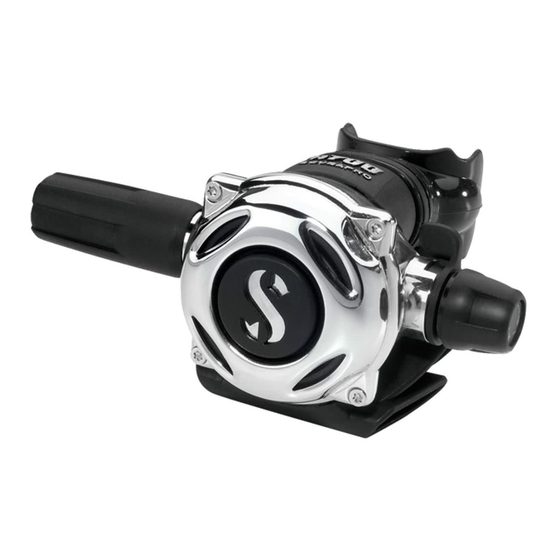
A700 Step-
by-step
maintenance
procedures.
Refer to schematic for
part identification.
Rene' Dupre' - Technical Training
Manager – 8/2009 Copyright,
Modified 7/2010
Advertisement
Table of Contents

Related Manuals for Uwatec A700


Summary of Contents for Uwatec A700
- Page 1 A700 Step- by-step maintenance procedures. Refer to schematic for part identification. Rene' Dupre' - Technical Training Manager – 8/2009 Copyright, Modified 7/2010 Important note: The following information is not designed to be a complete training guide for servicing the listed SCUBAPRO regulators.
- Page 2 A700 Step-by-step maintenance procedures. To properly service the A700 second stage, the following or suitable alternatives are required. SCUBAPRO universal tool P/N 43.040.000. Purchase direct from SCUBAPRO. Pneumatic adjusting tool. Recommend source: www.scubatools.com TORX® 10 Driver. Recommended source: Your favorite hardware store.
- Page 3 Nothing is gained by removing the nut; it is for as necessary. cosmetic purposes only and held using factory applied soft thread locking agent. Submerging the A700 case into an ultrasonic unit, using SCUBA industry-marketed Dive switch ultrasonic cleaning solutions is recommended to safely Min / Max clean case.
- Page 4 A700 Step-by-step maintenance procedures. 11. Lift the decal from 16. Remove both the the adjustment knob, shaft o-ring and using a suitable sleeve o-ring, using a device. A new decal is brass pick. supplied in the A700 maintenance kit. technician 17.
- Page 5 A700 Step-by-step maintenance procedures. 22. Expel o-rings “Flow deflector” out of the (aspirator) need not be grooves (slightly) removed! with one set of 1 - Expel figures and shove If you must – it is a snap off with other.
- Page 6 A700 Step-by-step maintenance procedures. 31. Remove inlet tube 35. To release the clamp lock, o-ring. position your tool of choice on one of the outside “guides” of clamp locking mechanism – rather than the “hook‟ itself. 32. Grasp, twist and 36.
- Page 7 A700 Step-by-step maintenance procedures. We are now ready to clean the separate components, using an ultrasonic cleaner and suitable solutions, specifically marketed by SCUBA industry suppliers. One source for such items is: Global Manufacturing Company. Following is an excerpt from their web site.
- Page 8 A700 Step-by-step maintenance procedures. 6. With the adjustable orifice slots at the 12 and 6 o‟clock position – install Reassembly… the 132 o-ring using both thumbs. 1. Push the “mouthpiece 7. Apply a dot of quality support” (trim collar) onto...
- Page 9 A700 Step-by-step maintenance procedures. Test for air-tight integrity by capturing air. Refresh these 11-A. Seal the LP seat components with new o- hole with thumb. rings. 11-B. Place the balance Following are some chamber onto the stem suggestions – to facilitate just enough to cover the assembly.
- Page 10 A700 Step-by-step maintenance procedures. 17. Push “micro adjust” 22. Prep the „dive switch” into the “adjustment by installing both o-rings shaft” and hold with supplied in the finger-pressure. maintenance kit. Note the shortcut! 18. Using a flat blade Continued… screw driver, inserted...
- Page 11 A700 Step-by-step maintenance procedures. 25. Place the “dive 28. Lubricate and install switch” assembly into the the 347 inlet tube o-ring. case. Orient the long-tab (towards the mouthpiece) and engage into the “flow deflector-guides. Note: The 2 “dive switch” 29. Engage function #7 tabs, engage into the 2 into the orifice slots.
- Page 12 A700 Step-by-step maintenance procedures. 30. Check for previous 36. Align the cover (with folds/creases on the screws and o-rings diaphragm “lip”. already installed). Any imperfections found merits replacement. 31. Be certain the entire 37. Begin to lightly snug circumference of the the 4 TORX®...
- Page 13 Refer and review the SCUBAPRO A700 movie-tutorial. Let‟s proceed by connecting an inline adjustment tool Now charge the A700 with intermediate pressure air… Set the Diver inhalation control knob to its “lightest” setting. Note the two (ll) bars. Place dive switch to MIN.
Need help?
Do you have a question about the A700 and is the answer not in the manual?
Questions and answers