
Related Manuals for Saunders CRANE I-VUE

Summary of Contents for Saunders CRANE I-VUE
- Page 1 Saunders® I-VUE Intelligent Sensing Technology Quick Start Guide www.saundersI-VUE.com www.cranechempharma.com Rev 1.00...
-
Page 2: Table Of Contents
Quick Start Guide Table of Contents Basic Safety Instructions Scope of Supply Overview Basic Installation Guide & Hazardous Area Installation (Automatic) Self-Calibration (Integral Solenoid) Hand-Calibration (Remote Solenoid) Switching Outputs Options Forcing the Integral Solenoid Troubleshooting Quick Start Guide Basic Safety Instructions These instructions do not make allowance for: Contingencies and events which may arise during the installation, operation, and maintenance of the sensor. -
Page 3: Scope Of Supply
Magnetic Target Visual Position Indicator Magnetic Key Cable Mounting Plate (optional) (optional) 3/2 Integral Solenoid (optional) A full range of additional accessories and spares are available from Saunders® on request. Please contact us for more information www.saundersI-VUE.com www.cranechempharma.com Rev 1.00... -
Page 4: Overview
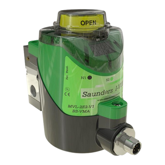
The Saunders® I-VUE Overview Ring of super bright LED’s Indicate valve position (Red = Closed; Green = Open) LED ‘Smart Window’ For programming and information displa LED Indicators Magnetic Buttons N1, S2, N3 To allow configuration with the magnetic key, the... - Page 5 Saunders® I-VUE Basic Installation Guide Visual Position Indicator Sensor Electronics Module Magnetic Target Sensor Mounting Base Cable connector (available in various types, contact Saunders® for further information) Actuator www.saundersI-VUE.com www.cranechempharma.com Rev 1.00...
- Page 6 V16 = M12 6-pin ASI3.2 BS-VSMA Example: with ASi v3.2 and Flat Cable Connector and 1/8" BSP Aluminium Solenoid Meaning: I-VUE Sensor Note: Configurations are dependent upon communication type, network protocol etc. Contact Saunders® for more information www.saundersI-VUE.com www.cranechempharma.com Rev 1.00...
- Page 7 Basic Installation Guide Tools Required: For actuators that require a mounting Philips or Flat head screwdriver kit. Please contact Saunders for the 8 mm open ended spanner relevant installation procedure Spanner to suit air fittings Low strength threadlock adhesive (recommended) Thread sealing compound for pneumatic fittings (if required) Screw magnetic target into actuator indicator.
- Page 8 Saunders® I-VUE Basic Installation Guide Re-attach sensor electronics module to the sensor mounting base via the 3 screws Connect any air fittings and tube to the actuator (and I-VUE solenoid if integral solenoid is fitted) Note: Supply pressure not to exceed 8 bar (116 PSI)
- Page 9 Saunders® I-VUE Hazardous Area Installation The Saunders® I-VUE is suitable for use in Hazardous Areas, Class I, Division 2 The Saunders® I-VUE cannot be installed in hazardous areas without a safety lock to prevent the connection or disconnection of the power supply/command cable with the power source connected.
- Page 10 Saunders® I-VUE Hazardous Area Installation Safety Lock Features o Warns the operator to not connect or disconnect Saunders® I-VUE when the power supply is energized. o Prevents disconnection - it removes the access to the locknut of the connector. o A tool is required for removal.
-
Page 11: Switching Outputs Options
Saunders® I-VUE Switching Output Options Enter I-VUE Menu by holding the Green S side of the key over the S2 target – the screen displays “Config” Scroll through I-VUE menu by using the Black N side of the key over the N1 or N3 targets... - Page 12 Saunders® I-VUE Self-Calibration (Integral Solenoid) Note: This guide only details self-calibration at the I-VUE unit. For calibration via a network, please refer to full IOM manual. Minimum required valve travel: 3mm Hold the black N side of the magnetic key over N3.
- Page 13 Saunders® I-VUE Hand-Calibration (Remote Solenoid) Before the Saunders® I-VUE can be calibrated, the unit must be set to Remote Solenoid Mode Warning: Self-Calibration will perform valve cycling and thus care must taken as the valve will move Enter I-VUE Menu by holding the green side of the key over the S2 target –...
- Page 14 Saunders® I-VUE Hand-Calibration (Remote Solenoid) Ensure “HSol” has ben selected from the “Sol Option” menu before performing calibration Minimum required valve travel: 3mm Hold the black N side of the magnetic key over N3. The LED indicator will light-up red.
-
Page 15: Forcing The Integral Solenoid
Saunders® I-VUE Forcing the Integral Solenoid The integral solenoid can be forced in the following ways: Pulsed – By depressing and releasing the manual override button on the solenoid. Locked-Off – By depressing the manual override button on the solenoid and turning it a quarter turn (90°) with a screwdriver. -
Page 16: Troubleshooting
Saunders® I-VUE Troubleshooting In the event of an alarm, remedy the problem. If successful the alarm will clear itself The input bits in these tables are factory default settings. If the output option is switched from nC to nO the input bit 1 and input bit 0 will be inverted. - Page 17 Saunders® I-VUE Notes ______________________________________ ______________________________________ ______________________________________ ______________________________________ ______________________________________ ______________________________________ ______________________________________ ______________________________________ ______________________________________ ______________________________________ ______________________________________ ______________________________________ ______________________________________ ______________________________________ ______________________________________ ______________________________________ ______________________________________ ______________________________________ ______________________________________ ______________________________________ www.saundersI-VUE.com www.cranechempharma.com Rev 1.00...
- Page 18 Saunders® I-VUE Notes ______________________________________ ______________________________________ ______________________________________ ______________________________________ ______________________________________ ______________________________________ ______________________________________ ______________________________________ ______________________________________ ______________________________________ ______________________________________ ______________________________________ ______________________________________ ______________________________________ ______________________________________ ______________________________________ ______________________________________ ______________________________________ ______________________________________ ______________________________________ www.saundersI-VUE.com www.cranechempharma.com Rev 1.00...
- Page 19 Saunders® I-VUE Notes ______________________________________ ______________________________________ ______________________________________ ______________________________________ ______________________________________ ______________________________________ ______________________________________ ______________________________________ ______________________________________ ______________________________________ ______________________________________ ______________________________________ ______________________________________ ______________________________________ ______________________________________ ______________________________________ ______________________________________ ______________________________________ ______________________________________ ______________________________________ www.saundersI-VUE.com www.cranechempharma.com Rev 1.00...
- Page 20 www.saundersI-VUE.com www.cranechempharma.com Rev 1.00...
Need help?
Do you have a question about the CRANE I-VUE and is the answer not in the manual?
Questions and answers