
Subscribe to Our Youtube Channel
Related Manuals for Saunders M-VUE

Summary of Contents for Saunders M-VUE
- Page 1 Installation, Operation and Maintenance Manual Saunders® M-VUE Intelligent Sensing Technology www.cranecpe.com Crane ChemPharma & Energy...
-
Page 2: Table Of Contents
Basic Saftey Instructions ...............................4 Scope of Supply ................................5 Overview ....................................6 Basic Installation Guide ............................7-11 Mounting the Solenoid Valve ........................9 Mounting M-VUE to an Actuator ......................10 Solenoid Valve Pneumatic Connections ....................11 Calibration ..................................12-16 Integral Solenoid ..............................13 Remote Solenoid ............................... 14 AS-Interface ................................15... - Page 3 Addressing ................................20 DeviceNet ..................................21-25 Wiring ..................................23 Communication Bytes ........................... 24 Setting Address on DeviceNet Units Only ..................25 Using the M-VUE Menus ............................ 26-28 Technical Data ................................. 29 Troubleshooting: Alarms ............................30 Dimensions ..................................31 www.cranecpe.com Crane ChemPharma & Energy...
-
Page 4: Basic Saftey Instructions
Basic Safety Instructions These instructions do not make allowance for: • Contingencies and events which may arise during the installation, operation, and maintenance of the sensor. • Local safety regulations; the operator is responsible for observing these regulations, also with reference to the installation personnel. -
Page 5: Scope Of Supply
Scope of Supply A full range of additional accessories and spares are available from Saunders® on request. Please contact us for more information Sensor Electronics Module Sensor Mounting Base Magnetic Target with visual indicator Exhaust Block Spare Magnetic Key 3/2 Integral Solenoid (optional) -
Page 6: Overview
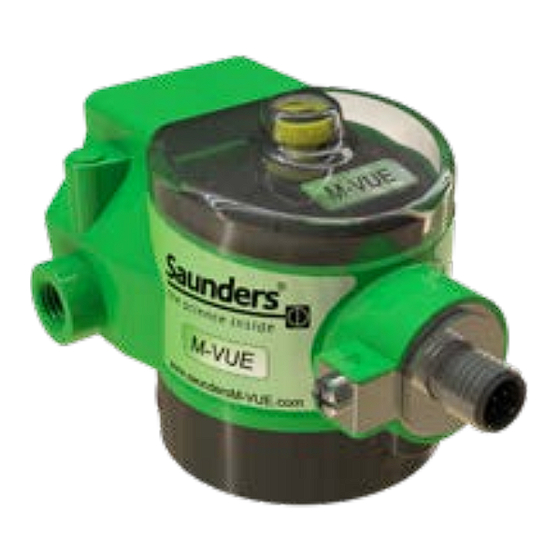
Overview Magnetic Buttons H1 and H2 to allow configuration with the magnetic key Mechanical position indicator Ring of super bright LEDs Magnetic button (Indicate valve connection indication position) Optional solenoid valve Magnetic key for use with H1 and H2 magnetic buttons Crane ChemPharma &... -
Page 7: Basic Installation Guide
Basic Installation Guide Sensor Electronic Module Cable connector (Available in various types, contact Saunders® for further information.) Sensor Mounting Base www.cranecpe.com Crane ChemPharma & Energy... - Page 8 V15= M12 5-Pin EXAMPLE: M-VUE-DNC-VM + BM-V + E MEANING: M-VUE Sensor with DeviceNet, 7/8” 5 Pin connector, 1/8” NPT Solenoid Valve and 1/8” Exhaust NPT Block Note: Configurations are dependent upon communication type, network protocol etc. Contact Saunders® for more information Crane ChemPharma &...
-
Page 9: Mounting The Solenoid Valve
• Philips or Flat head screwdriver 8 mm open ended spanner to suit air fittings. • Low strength threadlock adhesive (recommended) • Thread sealing compound for pneumatic fittings (if required) Note: For actuators that require a mounting kit. Please contact Saunders for the relevant installation procedure O-RINGS... -
Page 10: Mounting M-Vue To An Actuator
Optional Exhaust Port Block Connect any air fittings and tube to the actuator(and M-VUE solenoid if M-VUE can be equipped with an optional integral solenoid is fitted) exhaust block if air used by pneumatic Note: Supply pressure not to exceed 8 bar (116 PSI) actuator needs to be ported out of a classified area. -
Page 11: Solenoid Valve Pneumatic Connections
Basic Installation Guide Solenoid Valve Pneumatic Connections The size of the pneumatic connections offered are 1/8” NPT or BSP. Internal connection bays are Stainless Steel reinforced. Note: The exhaust block is optional and must be ordered separately. Inlet Pressure Port 1: Connection to main air supply Note: Supply pressure not to exceed 8 bar (116 PSI) Outlet Pressure Port 2: Connection to pneumatic actuator Exhaust Port 3: Air consumed by the actuator exits out of Port 3 to the... -
Page 12: Calibration
Calibration Calibration and Setting Options The features of M-VUE are dependent on both the network/communication protocol and the use of integral or remote solenoid. The table below outlines the possibilities of each of the M-VUE network protocols AS-Interface DeviceNet Feature... -
Page 13: Integral Solenoid
It will automatically open and close 3 times. If the self calibration routine is successful all the LEDs will flash green for 2 seconds and M-VUE will return to normal run mode If the self calibration routine fails all LEDs will flash red for 2 seconds. -
Page 14: Remote Solenoid
Hand-Calibration Remote Solenoid 3 Seconds to Confirm Asking for Close Asking for Open Hand Calibration Hold the magnetic key over H2 for 3 seconds . The ring of LED’s will flash green for 2 seconds (this indicates Configuration Mode has been accessed) Hold the magnetic key over H1 to select the Hand Calibration Mode (P2 LED must be flashing) Confirm the selection of P2 by holding the magnetic key over H2 for 3 seconds P2 LED will light red. -
Page 15: As-Interface
Calibration with Integral Solenoid (AS-Interface) Self-Calibration of the M-VUE is controlled by Output Bit 2 on AS-Interface networks. By changing Output Bit 2 from 0 to 1, the M-VUE unit can perform its self-calibration cycle. The self-calibration sequence is automatic and will cycle the aseptic valve three times. -
Page 16: Devicenet
M-VUE can control a remote solenoid to cycle a pneumatic actuator and perform remote calibration. • By changing Output Byte 1, Bit 2 from 0 to 1, the M-VUE unit can perform its self-calibration cycle. • Input Byte 1, Bit 4 must be used to command a signal to control a remote solenoid. -
Page 17: Point-To-Point Wiring
Output 1 indicates when the valve is CLOSED and sends this signal to the PLC input card Output 2 indicates when the valve is OPEN and sends this signal to the PLC input card. These outputs can be reversed in the “Output Option” within the M-VUE menu Wiring Diagram Note: For units without integral solenoid, pin 5 is not active. -
Page 18: As-Interface (As-I)
AS-Interface (AS-i) Wiring Pin Configuration Wire Colour Designation Brown AS-i (+) Blue AS-i (-) Wiring Diagram Crane ChemPharma & Energy www.cranecpe.com... -
Page 19: Communication Bits
Valve Open Valve Closed Not Used Successful Calibration-Run Mode Self Calibration Mode Active (Stay in ‘1’ if Self Calibration Fail) M-VUE Asks External Solenoid: OFF M-VUE Asks External Solenoid: ON Output Bits Bit 3 Bit 2 Bit 1 Bit 0... -
Page 20: Addressing
AS-Interface (AS-i) Addressing Addressing the Saunders® M-VUE Addressing the M-VUE can be performed with a standard AS-i Handheld programmer or by network configuration software. The number of addresses depends on the AS-i version. The default address for M-VUE is 0. -
Page 21: Devicenet
The Saunders® DeviceNet M-VUE can be utilised with the following system topographies: • Branch Line • Tree • Line The Saunders® DeviceNet M-VUE can not be utilised with the following system topographies: • Star • Ring DeviceNet System Cabling Thick Cable The DeviceNet thick cable is also known as a Trunk Cable. - Page 22 DeviceNet Communication Setting the Address The address can be set in 3 ways - by the software configuration, via handheld or by the menu on the M-VUE unit. M-VUE can be addressed from 00 to 63. To set the address at the M-VUE unit, please see “Setting the Address” section.
-
Page 23: Wiring
DeviceNet Wiring Pin Configuration Wire Colour Designation Bare/Drain 24 V dc (+) Black 24 V dc (-) White CAN_H Blue CAN_L Wiring Diagram www.cranecpe.com Crane ChemPharma & Energy... -
Page 24: Communication Bytes
DeviceNet Communication Bytes Communication Bytes Input Bits Input Meaning Byte Valve in Mid-Stroke Position Valve Closed Valve Open Not Used Solenoid is Forced (at Sensor) Self Calibration Status (1=Failed) Asking PLC to Power External Solenoid OFF Asking PLC to Power External Solenoid ON General Alarms Not Used Not Used... -
Page 25: Setting Address On Devicenet Units Only
Important! The M-VUE cannot have the same address as other network equipment, if this occurs, the equipment with the same address will not work. Once the address is set, the network speed (Baud rate) at which M-VUE will communicate in the network also needs to be set (See setting network speed/baud rate). -
Page 26: Using The M-Vue Menus
Using the M-VUE Menus Overview Solenoid Option The Main Menu is accessed via the The Main Menu is accessed via the magnetic buttons H1 and H2 and is used to calibrate magnetic buttons H1 and H2 and is used to and program the sensor. - Page 27 Using the M-VUE Menus Output Inversion The Main Menu is accessed via the magnetic buttons H1 and H2 and is used to calibrate and program the sensor. Confirm on H2 Change to Output Inversion After H2 has been used to confirm...
- Page 28 Setting Network Speed/Baud Rate (DeviceNet Units Only) The Main Menu is accessed via the This parameter allows the data rate to be selected. The M-VUE can communicate data at a rate of 125, 250 or 500 Kbit/s (MVUE’s default Baud Rate is 125 Kbits/s) IMPORTANT! The magnetic buttons H1 and H2 and is used to calibrate and program the sensor.
-
Page 29: Technical Data
0.25”–2.00” (DN8-DN50) Type 24Vdc 31.5 Vdc 24 Vdc Temperature Range 0°C to + 70°C M-VUE (solenoid OFF) < 35 mA < 35 mA < 40 mA Continuous sensing via Hall Effect sensors Sensing Technology M-VUE (solenoid ON) < 63 mA <... -
Page 30: Troubleshooting: Alarms
Troubleshooting Alarms M-VUE can display three alarms: • Alarm 1: Unexpected position change • Alarm 2: Stroke out of range • Alarm 3: Stop at the middle of the way Alarm 1: This alarm indicates that an unexpected position change has occurred. P1... -
Page 31: Dimensions
Dimensions www.cranecpe.com Crane ChemPharma & Energy... - Page 32 (ALOYCO®, CENTER LINE®, COMPAC-NOZ®, CRANE®, DEPA®, DUO-CHEK®, ELRO®, FLOWSEAL®, JENKINS®, KROMBACH®, NOZ-CHEK®, PACIFIC VALVES®, RESISTOFLEX®, REVO®, SAUNDERS®, STOCKHAM®, TRIANGLE®, UNI-CHEK®, WTA®, and XOMOX®) are registered trademarks of Crane Co. All rights reserved. © Crane ChemPharma & Energy...
Need help?
Do you have a question about the M-VUE and is the answer not in the manual?
Questions and answers