Advertisement
1. Nut cover
2. Castellated nut
3. Split pin
4. Bearing plate, inner
5. Bolt kit
6. Rubber bearing
7. Drawbeam sleeve
8. Bushing
9a. Bar spacer washers 4 mm
9b. Bar spacer washer 10 mm
10. Bearing plate, outer
11. Rubber bearing
12. Coupling jaw
13. Mechanism
14. Guiding funnel
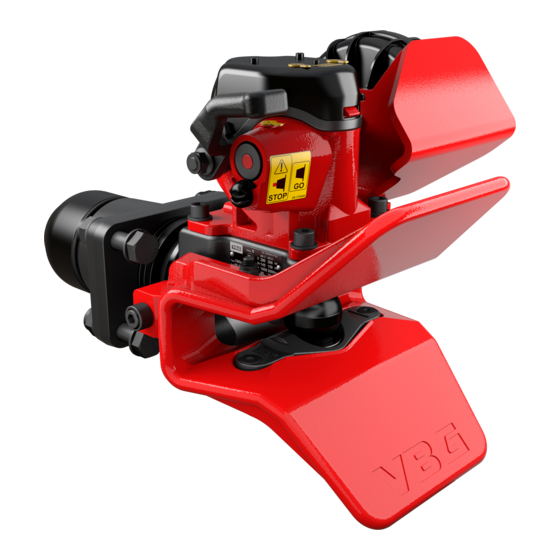
VBG 795V
General
VBG 795 V, part no.: 09-052000
The VBG 795V coupling is designed for centre axle
trailers, full trailers with boggiefront axles and dollys
that use a Ø 57.5 mm drawbar eye as per the VBG
standard.
The coupling should be mounted to a drawbeam which
fulfi ls the requirements of ISO 3584 cat. 3. The web
thick-ness in the middle of the drawbeam must be 13-
30 mm with an inner clearance of at least 160 mm. It is
easiest to mount it to a VBG drawbeam, all of which
meet these requirements.
The coupling has a high-quality corrosion resistance
through electrolytic pre-treatment and a top-coat with
very high wear resistance. To maintain the high quality
of the surface treatment, VBG recommend that no
futher paint is added to the coupling. If the coupling is
over-painted, you run the risk of operational problems,
a sticking signal/indicator pin or that important informa-
tion is overpainted. Moving parts, plates and
decals must all be thoroughly covered if the coupling
is repainted.
Identify all parts before installation. Installation shall be
done in a proper and competent manner. Always follow
the instructions.
All directives and instructions should be kept in the
vehicle for future service and maintenance.
Contents
instructions ........................2
Safety check ......................................6
Service - maintenance ......................9
Driver instructions ...........................12
Spare parts list Power actuator .......16
Spare parts list VBG 795V ...............17
2005-04-19
38-134800k
Advertisement

Related Manuals for VBG 795V


Summary of Contents for VBG 795V
-
Page 1: Table Of Contents
VBG 795 V, part no.: 09-052000 The VBG 795V coupling is designed for centre axle trailers, full trailers with boggiefront axles and dollys that use a Ø 57.5 mm drawbar eye as per the VBG standard. The coupling should be mounted to a drawbeam which fulfi... -
Page 2: Mounting Instructions
Lubricate the coupling weekly with VBG mechanism oil or similar thin oil. For the maximum effect, the coupling should be open when it is being lubricated. VBG do not recommend the use of central greasing systems. • Lubrication points (see adjacent drawing). - Page 3 Mounting of a power actuator If the coupling is to be equipped with a power actuator, follow the directions below. Mounting of the actuator on the bracket ca 5° • Turn the shaft on the actuator clockwise until it can go no further and then turn it back approx.
- Page 4 Mounting of the control box • Mount the control box close to the coupling so that the operation of the coupling can be watched. The control box must be positioned so that it is well protected from vibration, impact, dirt and ice formation. Alt.
- Page 5 1 mm). Tighten the nuts (g), tightening torque max. 2 Nm. • If VBG’s Indicator kit (part no. 09-099200) is used – connect the inductive sensor according to the mounting instructions. Otherwise connect the inductive sensor to the vehicle’s electrical system (24 V).
-
Page 6: Safety Check
Safety check Carry out the safety check once a week. If the check shows that any of the wear limits have been exceeded or that the coupling´s function is reduced, rectifi cation must be carried out immediately. Before any work or service is carried out on the coupling all air supply to the coupling must be cut off. - Page 7 Vertical play in the coupling bolt max 5.0 mm Lubrication Lubricate the coupling weekly with VBG mechanism oil or similar thin oil. For maximum effect, the coupling should be open when it is lubricated. • Lubrication points (see drawing on the left)
- Page 8 Safety check contd. Operation check - power actuator • Fold out the yellow handle (d). Simultaneously press on the mark “Press” on the handle and turn the handle anti-clockwise to “OPEN”. Then turn it back to “CLOSE”. The coupling pin should remain in the up/open posi- tion.
-
Page 9: Service - Maintenance
Service - maintenance • It is important to remember that a coupling is a safety critical item and should be treated as such. Proper preventive maintenance, inspection and lubrication are essential for a long, safe and trouble-free service life. • The length of service intervals depends on the type of trailer, load, road- and weather conditions etc. - Page 10 • Change the bushings using VBG service tools. Press out the old bushings from below and press in the new bushings from above as per the fi gure.
- Page 11 Lubricate the coupling with VBG mechanism oil. For maximum effect, the coupling must be open when it is being lubricated. • Lubrication points (see drawing on the left) Attachment check • Remove the coupling jaw and clean the shaft of rust and rubber residue.
-
Page 12: Driver Instructions
Driver instructions Warning! Never put your fi ngers into the coup- ling mouth because of the danger of them being crushed. Uncoupling without power actuator Stand by the coupling handle. Lift the handle 90º, the handle locks. The coupling is now open. Uncouple the trailer. - Page 13 Coupling without power actuator Stand by the coupling handle. Lift the handle 90º, the handle locks. The coupling is now open. Connect to the trailer. STOP 38-08100 Check that the Indicator pin is completely in. If the Indicator pin is not completely in, the coupling is open and driving is not, under any circumstances, permitted! Contact nearest workshop for remedial measures.
- Page 14 Warning! Never put your fi ngers into the coupling mouth because of the danger of them being crushed. Uncoupling Simultaneously press on the handle where it says “Press” and turn the handle anti-clockwise to “OPEN”. Then turn it back to “CLOSE”. Uncouple the trailer.
- Page 15 Coupling Simultaneously press on the handle where it says “Press” and turn the handle anti-clockwise to “OPEN”. Then turn it back to “CLOSE”. Couple to the trailer. Check that the signal pin goes fully in, and that the green warning lamp in the cab is on.
-
Page 16: Spare Parts List Power Actuator
Tel +32 24810900 NL - 3009 AS ROTTERDAM Fax +32 24633659 Tel +31 10 2888 600 Fax +31 10 2888 601 DENMARK VBG PRODUKTER A/S NEW ZEALAND Industribuen 20-22 TRANSPORT SPECIALTIES LTD DK – 5592 EJBY P O BOX 98-971 Tel +45 6446 1919 NZ - S.A.M.C., Wiri, AUCKLAND...
Need help?
Do you have a question about the 795V and is the answer not in the manual?
Questions and answers