
Related Manuals for Leuze electronic OGS 600


Summary of Contents for Leuze electronic OGS 600
- Page 1 OGS 600 Optical guidance sensor O r i g in a l op e r a ti n g i n s tr uc t i o ns...
- Page 2 © 2017 Leuze electronic GmbH + Co. KG In der Braike 1 D-73277 Owen / Germany Phone: +49 7021 573-0 Fax: +49 7021 573-199 http://www.leuze.com info@leuze.com Leuze electronic OGS 600...
-
Page 3: Table Of Contents
5.3.1 OGS 600-…/D3-M12.8 with RS485 interface........21... - Page 4 5.3.2 OGS 600-…/D2-M12.8 with RS422 interface........21 5.3.3...
- Page 5 Performing a reset on the OGS 600 ........
- Page 6 General technical data OGS 600 ........
-
Page 7: About This Document
About this document About this document This technical description contains information regarding the proper use of the OGS 600 optical guidance sensors. Explanation of symbols The symbols used in this technical description are explained below. CAUTION This symbol precedes text messages which must strictly be observed. -
Page 8: Safety
It corresponds to the state of the art. Intended use The OGS 600 optical guidance sensor measures the contrast of a guide trace that is affixed to the ground. The sensor supplies the vehicle's position data on the guide trace, which determines the course of travel. -
Page 9: Competent Persons
The device must not be tampered with and must not be changed in any way. The device must not be opened. There are no user-serviceable parts inside. Repairs must only be performed by Leuze electronic GmbH + Co. KG. Competent persons Connection, mounting, commissioning and adjustment of the device must only be carried out by competent persons. -
Page 10: Device Description
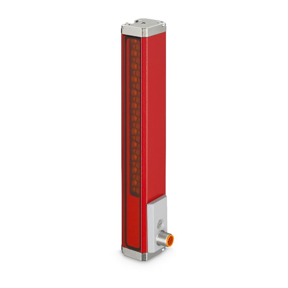
Device description Device description Device overview OGS 600-280/CN-M12 OGS 600-140/D…-M12.8 A Integrated illumination – transmitter (small lenses) B Receiver modules – receiver (large lenses) C Groove with 2 sliding blocks for fastening the mounting bracket D 2 x M12 connector, 5-pin E 1 x M12 connector, 8-pin Figure 3.1:... -
Page 11: Performance Characteristics
B Left edge of guide trace C Right edge of guide trace D Width of the sensor's measurement field E AGV direction of travel Figure 3.2: Schematic illustration of the guide trace under the optical guidance sensor Leuze electronic OGS 600... -
Page 12: Measurement Time
If floor markings occur which, despite activated filters, are detected as valid, then these markings are output. The vehicle's control unit must ensure that position jumps in the output traces are detected and that they are not followed. Leuze electronic OGS 600... -
Page 13: Output Value
The sensor outputs the position of the left edge and the right edge of the optical guide trace in mm * 10. The output value range is therefore: • Short version OGS 600-140…: 0 … 1500. • Long version OGS 600-280…: 0 …... - Page 14 C Output value: Position of left edge D Output value: Position of right edge x Position of left edge of guide trace under sensor y Output value: Edge positions Figure 3.4: Sensor characteristic curve with one trace (long version) Leuze electronic OGS 600...
-
Page 15: Example: Guide Trace Detection With Active "Trace Width" Filter
D, E Trace too wide according to active "Trace width" filter Width of the sensor's measurement field AGV direction of travel Objects not detected as trace Figure 3.5: Schematic illustration of the guide trace under the optical guidance sensor Leuze electronic OGS 600... -
Page 16: Guide Trace Requirements
Table 3.6: Color comparison between the sensor and the human eye. NOTE A detailed table with sensor measurement values can be found in the appendix (see chapter 13 "Appendix – Sensor measurement values for RAL colors"). Leuze electronic OGS 600... -
Page 17: Trace Width
3.3). The trace must have a minimum width so that a sufficiently good contrast can be achieved. The "Trace width" filter can be adjusted to the trace by means of a trace width teach. The recommended trace width is approx. 30 … 40mm. Trace width OGS 600-280… OGS 600-140… Maximum 266mm 106mm... -
Page 18: Connection Technology
Use only shielded connection cables! Operating and display elements The optical guidance sensor does not have any operating elements or indicators. The sensor is operated and its configuration checked only via the serial interface or via the CAN bus. Leuze electronic OGS 600... -
Page 19: Mounting
Angled sensor mounting to prevent unwanted reflection The sensor can be mounted using the mounting brackets included in the delivery (see chapter 4.3 "Mounting accessories"). They ensure that the sensor is pointing at the floor at the correct angle. Leuze electronic OGS 600... -
Page 20: Selecting A Mounting Location
• 2x M6 sliding blocks (inserted in the groove) • 2x mounting brackets for mounting the sensor at an angle of 20°. NOTE Dimensioned drawings! The dimensioned drawings with the installation dimensions of the sensor can be found in Chapter 11.2. Leuze electronic OGS 600... -
Page 21: Electrical Connection
If faults cannot be cleared, the device should be switched off and protected against accidental use. NOTE Protective Extra Low Voltage (PELV)! The OGS 600 optical guidance sensors are designed in accordance with protection class III for supply by PELV (protective extra-low voltage with reliable disconnection). NOTE Shielding connection! The shielding is connected via the M12 connector housing. -
Page 22: Voltage Supply
Electrical connection Voltage supply The OGS 600 guidance sensors are designed for a voltage supply of 18 … 30VDC (PELV – protective extra low voltage with reliable disconnection). The current consumption with 24 V DC is approx. 180 mA. 5.2.1... -
Page 23: Pin Assignment
Not connected (A-coded) n. c. Not connected Thread Functional earth (housing) Table 5.1: PWR/RS485 – Pin assignment for OGS 600 with RS485 interface 5.3.2 OGS 600-…/D2-M12.8 with RS422 interface PWR/RS422, 8-pin M12 connector, A-coded Name Comment IN / OUT Operating voltage +18 … +30VDC... -
Page 24: Ogs 600
Switching output Signal line of RS232 interface M12 plug (A-coded) Thread Functional earth (housing) Table 5.3: PWR/RS232 – Pin assignment for OGS 600 with CANopen/RS232 interface CAN, 5-pin M12 socket, A-coded Name Comment IN / OUT SHIELD CAN functional earth n. -
Page 25: Switching Inputs/Outputs
If the contrast is greater or less than the limit value, the switching output is activated. NOTE Deactivation of a switching output Both switching outputs SW_IO and IO can also be deactivated independently of each other. Leuze electronic OGS 600... - Page 26 6 Lower switching point Figure 5.1: Switching behavior of the switching outputs NOTE The switching outputs can be configured independently of each other as: • Push-pull switching output • PNP switching output • NPN switching output Leuze electronic OGS 600...
-
Page 27: Switching Output Sw_Io (Pin 4)
• Global error (UART index 200 , and CAN index 2020 ], value 0001 ) with detailed info in UART index 201 and CAN index 2020 Table 5.5: Configuration options for switching output SW_IO (pin 4) Leuze electronic OGS 600... -
Page 28: Io Switching Output/Switching Input (Pin 2)
• Global error (UART index 200 , and CAN index 2020 ], value 0001 ) with detailed info in UART index 201 and CAN index 2020 Table 5.6: Configuration options IO switching output/switching input (pin 2) Leuze electronic OGS 600... -
Page 29: Function Of The Io Switching Input (Pin 2)
UART index 76 (CANopen ) Qproperty. index 2005 This setting has no effect on the output of process data. NOTE Deactivation of the switching input The switching input IO can also be deactivated. Leuze electronic OGS 600... -
Page 30: Connection To The Pc Via Rs232/Rs422/Rs485
D Optical guidance sensor Figure 5.2: Connection of the OGS 600 to the PC using the RS485 interface The adapter set and the Y-connection cable are available as accessories on request. Information about installation and use of the software can be found in Chapter 6 "Configu- ration/diagnostic software"... -
Page 31: Configuration/Diagnostic Software
Configuration software OGS 600 The control software for the OGS 600 does not need to be installed. This is a directly execut- able .exe file. No admin rights are required. The software functions with all RS485, RS422, RS232 serial interfaces. -
Page 32: Starting The Configuration/Diagnostic Software
• Changing filter settings manually • Performing the various teach modes for the filters • Querying of the process data • Reading out of valid and invalid traces • Reading and writing indices • Configuring the CANopen properties Leuze electronic OGS 600... -
Page 33: Configuring The Sensor - Overview Of Functions
Perform the teach –> System Command (UART index 2 and CAN index 2000 value: 193 Read UserState (UART index 151 and CAN index 2011 evaluation of the data –> wait until bit 1 (angle compensation OK) is set. Leuze electronic OGS 600... -
Page 34: Configuring The Guide Trace - Light, Dark, Retro-Reflective
For the sensor, this signal looks like a light trace. With this setting, the transmitting current of the LEDs for the sensor illumination is reduced in order to fully utilize the dynamics of the electronics. Leuze electronic OGS 600... -
Page 35: Offset To The Edge Positions
Offset the process data output values from 0 … 3000 to -1500 … 1500. -150mm offset: -150mm * 10 = -1500. –> Write the value ’-1500’ in UserOffset (UART index 109 and CAN index 2010 NOTE If the offset is to be deactivated, the value 0 must be written. Leuze electronic OGS 600... -
Page 36: Switch
Left edge of guide trace Left edge of guide trace too wide Right edge of guide trace Right edge of guide trace too wide Figure 7.3: Type 1 and type 2 trace switches The sensor supports both switch types. Leuze electronic OGS 600... - Page 37 Typical value: approx. 5 … 20mm. Midpoint of a type 2 switch Dead zone Left edge of guide trace Right edge of guide trace Area with extremely low contrast Figure 7.4: Midpoint of type 2 switch Leuze electronic OGS 600...
-
Page 38: Switch" Function - Settings For Type 2 Switches
The vehicle decides which guide trace is used. The sensor does not know the decision made by the vehicle. To allow optimum configuration to be performed, the sensor must be informed of the number of the guide trace which is followed by the vehicle. Leuze electronic OGS 600... - Page 39 (10ms) after the query is sent for the first time. Deactivation of the "Switch" function Writing a ’0’ in SwitchNumber (UART index 170 and CAN index 2012 Writing of ’0’ in byte 2 PD-In1 during the process data query. Leuze electronic OGS 600...
-
Page 40: Index Accesses For Activation Of The "Switch" Function
= trace no. 1 = trace no. 2 = trace no. 3 = trace no. 4 = trace no. 5 = trace no. 6 Table 7.4: Settings for "Switch" function with process data query in byte 2 Leuze electronic OGS 600... -
Page 41: Trace Width" Filter
Left edge of guide trace Right edge of guide trace Trace too wide according to active "Trace width" filter Trace OK Teach threshold Figure 7.5: Application of the "Trace width" filter using a dark trace as an example Leuze electronic OGS 600... -
Page 42: Teaching The Trace Width
If the number of detected traces which, owing to the "Trace width" filter, are not output in the process data is greater or equal to one, then bit 3 is set in process data byte 2 Status PD. Leuze electronic OGS 600... -
Page 43: Index Overview For The "Trace Width" Filter
See also process data status byte, bit no. 3 (Chapter 8.1.4.1) UserMode 2002 Bit no. 2 If the bit is set, then the "Trace width" filter is active. Table 7.5: Index accesses for the "Trace width" filter Leuze electronic OGS 600... -
Page 44: Minimum Contrast" Filter
The value appears as a percentage [%] in the index. Calculation in the sensor: Contrast = │Amplitude_environment - Amplitude_trace│ TraceContrastMin = Contrast - ( Contrast * TraceContrastTol /100 ) Leuze electronic OGS 600... -
Page 45: Manual Configuration Of The Minimum Contrast
Bit 4 Minimum contrast error is set if the number of detected traces for which the contrast is less than TraceContrastMin, is greater than or equal to one. Leuze electronic OGS 600... -
Page 46: Index Overview For The "Minimum Contrast" Filter
1 = Minimum contrast warning See also process data status byte, bit no. 1 (Chapter 8.1.4.1) UserMode 2002 Bit no. 3 If bit = 1, then "Minimum contrast" filter is active. Table 7.6: Index accesses for the "Minimum contrast" filter Leuze electronic OGS 600... -
Page 47: Trace Amplitude" Filter
Right edge of guide trace Trace width Amplitude of background Amplitude of guide trace Invalid trace amplitudes (red area) TraceAmplitudeMin value TraceAmplitudeWarning value Figure 7.7: Application of the "Trace amplitude" filter using a dark trace as an example Leuze electronic OGS 600... -
Page 48: Teaching The Trace Amplitude
Calculation of dark guide trace: TraceAmplitudeWarning_threshold = TraceAmplitudeMin [LSB] - ( TraceAmplitudeMin [LSB] * TraceAmplitudeWarning ) Calculation of light guide trace: TraceAmplitudeWarning_threshold = TraceAmplitudeMin [LSB] + ( TraceAmplitudeMin [LSB] * TraceAmplitudeWarning ) Leuze electronic OGS 600... -
Page 49: Process Data Information For The "Trace Amplitude" Filter
1 = Trace amplitude warning See also process data status byte, bit no. 2 (Chapter 8.1.4.1) UserMode 2002 Bit no. 4 If bit = 1, then "Trace amplitude" filter is active Table 7.7: Index accesses for the "Trace amplitude" filter Leuze electronic OGS 600... -
Page 50: Index Overview - More Data On Correct And Incorrect Traces
…] TraceValidStatus 2025 [ Trace1, The warning is shown for each ]…[6 Trace2, trace. Trace3, …] Data: : contrast warning : trace amplitude warning Table 7.8: Index overview: direct access to all data of valid traces Leuze electronic OGS 600... - Page 51 [ Trace1, The error is shown for each ]…[6 Trace2, trace. Trace3, …] Data: : contrast error : trace amplitude error : trace width error Table 7.9: Index overview: direct access to all data of invalid traces Leuze electronic OGS 600...
-
Page 52: Commissioning
• Incorrect CRC: error telegram 8112 • Error during reception (parity error, ...): error telegram 8113 • Incorrect identifier: error telegram 8111 • Maximum time taken for the sensor to respond to a query: 1.2ms Leuze electronic OGS 600... -
Page 53: Index Access
Length indicates how much data is sent to the sensor; if the data length exceeds the object length, an error is returned. Process data Error n = node number Table 8.2: Identifiers for working with indices Leuze electronic OGS 600... - Page 54 Index Index Sub- Data n identifier lowbyte highbyte index Query Read Response Read Quantity Data n Data bytes Table 8.3: Example of a query to read byte Node no.: Index: 200 (LowByte: C8 , HighByte: 00 Leuze electronic OGS 600...
-
Page 55: Process Data
Status PD contains the eight most important pieces of information about the detected traces. Byte 3: Contrast is a value reduced to 8 bits and indicates the contrast of the trace. Byte 4: Data of the detected traces Byte n+1: The last byte is the CRC byte. Leuze electronic OGS 600... -
Page 56: Status Byte In The Process Data
Switch active see chapter 7.4 "Switch" Bit 7: No trace detected –> Check guide trace/background NOTE Data for traces (edge positions, contrast) which are declared as invalid by a filter is never output via the process data. Leuze electronic OGS 600... -
Page 57: Contrast Byte In The Process Data
To be able to compare the contrast value in the process data with the values in the indices of the "Minimum contrast" or "Trace amplitude" filters, the value from the process data must be multiplied by 100. Contrast = Hex2Dec(byte 3) * 100 Leuze electronic OGS 600... -
Page 58: Type 1 Process Data
With active "Trace width" filter, the "Switch" function can be used as an alternative (see chapter 7.4 "Switch"). In this case, additional information is sent in byte 2 (data) when the process data is requested. Leuze electronic OGS 600... - Page 59 Example response for type 1 process data Contrast = 120 * 100 = 12000 LSB Left edge of the trace = 1200 / 10 = 120.0 mm Right edge of the trace = 1300 / 10 = 130.0 mm Leuze electronic OGS 600...
-
Page 60: Type 4 Process Data
With active "Trace width" filter, the "Switch" function can be used as an alternative (see chapter 7.4 "Switch"). In this case, additional information is sent in byte 2 (data) when the process data is requested. Leuze electronic OGS 600... - Page 61 From the number of user data bytes, it is possible to calculate how many traces have been found: • per edge: 2 bytes • per trace: 2 edges => This results in 4 bytes of user data per trace. Leuze electronic OGS 600...
-
Page 62: Error Codes
UART: incorrect identifier Check identifier (for valid identifiers, see Table 8.2) 8112 UART: incorrect CRC Check CRC calculation 8113 Receive error (parity, …) Repeat several times, otherwise sensor defective Table 8.9: Error codes for data transfer Leuze electronic OGS 600... -
Page 63: Object Directory For Serial Interfaces (Uart)
[byte] type Index System Command System command See Table 8.12 Vendor Name Device manufacturer Leuze electronic GmbH + Co. KG string Vendor Text Manufacturer text Leuze electronic - the sensor people string Product Name Product designation <Product Name> string Product ID Part no. - Page 64 For manual configuration (changed by means 0… uint16 of a trace width teach!), 65535 unit: 0.1mm TraceWidthMin Minimum trace width For manual configuration (changed by means 0… uint16 of a trace width teach!), 65535 unit: 0.1mm Leuze electronic OGS 600...
- Page 65 Supply voltage warning Bit 9: Supply voltage error Bit 10: Teaching error Bit 11: Compensation error Bit 12: Switch function active Bit 13: Switch error: unknown trace Bit 14: No trace detected (number of edges < 2) Leuze electronic OGS 600...
- Page 66 (see Chapter 7.8) Contrast Minimum contrast of all traces Unit: [LSB] 0… uint16 65535 SupplyVoltage Supply voltage Unit: [mV] 0… uint16 65535 TempController Temperature controller Unit: [°C] 0… uint16 65535 Table 8.11: Object directory for serial interfaces (UART) Leuze electronic OGS 600...
-
Page 67: System Commands For Serial Interfaces
Mode: "Minimum contrast" filter ON Mode: "Minimum contrast" filter OFF Mode: "Trace amplitude" filter ON Mode: "Trace amplitude" filter OFF Delete angle compensation factors Delete error Delete error bits / error status Table 8.12: System commands Leuze electronic OGS 600... -
Page 68: Canopen Communication Protocol
The node ID can be set in two ways: • Via the object directory: Index Sub-index Name Description Length [byte] Data type 2001 Can Node No CAN node address uint16 • Via the Layer Setting Services function (LSS, see DS305 of CiA). Leuze electronic OGS 600... -
Page 69: Baud Rate Setting
• 125 kBit/s • 100 kBit/s • 50 kBit/s • 20 kBit/s • 10 kBit/s The OGS 600 is set to 1 Mbit/s by default. The baud rate can be set in two ways: • Via the object directory: Index Sub-index... -
Page 70: Communication Mechanisms Of The Ogs 600 In The Canopen Network
8.3.1.6 Objects All process data and parameters are stored as objects in the OGS 600. The object directory (see Chapter 8.4) is the compilation of all process data and parameters of the OGS 600. -
Page 71: Eds File
Commissioning 8.3.1.7 EDS file For the user, the object directory of the OGS 600 is available as an EDS file (Electronic Data Sheet). Download the EDS file for the device at www.leuze.com. NOTE Download EDS file from the Internet! ... - Page 72 Commissioning The exchange of process data is supported by the OGS 600 via the following accesses: • Event-controlled data transfer Here, the data of a node are transmitted as a message whenever a change to the pres- ent state occurs.
-
Page 73: Default 11 Bit Identifier
The OGS 600 sends an 11 bit identifier. 29 bit identifiers can be neither received nor sent by the OGS 600. The node address (address of the OGS 600) is part of the 11 bit identifier. The default iden- tifier and the node address give the COB ID, the value of which defines the prioritization in the arbitration. -
Page 74: Object Structure Of The Ogs 600
Overview of the CANopen-specific object area of the OGS 600 The following overview table shows the CANopen-specific communication objects from DS301 which are supported by the OGS 600. These operating instructions describe only the objects for which device-specific configurations can be performed. All other objects are stan- dard objects of the CANopen specification. -
Page 75: Process Data Objects
Commissioning 8.3.1.11 Process data objects The OGS 600 provides 4 transmit process data objects (TPDOs) and 1 receive process data object (RPDO). The TPDOs describe which objects are mapped to (integrated in) the TxPDO, and define the access (synchronous/asynchronous) to these objects. -
Page 76: Overview Of The Mapped Data In The Txpdos
2022 2022 2022 2022 object TxPDO4 Byte 0 Byte 1 Byte 2 Byte 3 Trace 6 Left edge low Left edge Right edge Right edge byte high byte low byte high byte Mapped 2022 2022 object Leuze electronic OGS 600... -
Page 77: Overview Of The Mapped Data In The Rxpdo
• 2: Trace 2 switch • 3: Trace 3 switch • 4: Trace 4 switch • 5: Trace 5 switch • 6: Trace 6 switch PD-In2: Reserve RxPDO Byte 0 Byte 1 PD-In1 PD-In2 Mapped 2051 object Leuze electronic OGS 600... -
Page 78: Overview Tpdos
(hex) index (hex) 1A01 3rd edge uint32 20220310 Content from object 2022 4th edge uint32 20220410 Content from object 2022 5th edge uint32 20220510 Content from object 2022 6th edge uint32 20220610 Content from object 2022 Leuze electronic OGS 600... - Page 79 Sync start value uint8 Sync start value Object 1A03 TPDO4 Index Sub- Name Data type Access Default Comment (hex) index (hex) 1A03 11th edge uint32 20220B10 Content from object 2022 12th edge uint32 20220C10 Content from object 2022 Leuze electronic OGS 600...
-
Page 80: Overview Rpdos
Inhibit time Reserve Event timer uint16 Event timer Sync start value uint8 Sync start value Object 1600 RPDO1 Index Sub- Name Data type Access Default Comment (hex) index (hex) 1600 PDO-CMD uint32 20510008 Content from object 2051 Leuze electronic OGS 600... -
Page 81: Canopen Object Directory
: contrast monitoring 2003 Q1Hysteresis Switching hysteresis for With trace monitoring: 0… uint16 switching output SW_IO (pin 4) range: 0…3000 (long device version), 65535 range: 0…1500 (short device version), unit: 0.1mm With contrast monitoring: range: 0…21200, unit: [LSB] Leuze electronic OGS 600... - Page 82 1…100 2 uint16 2010 TraceContrastTol Contrast tolerance Only required for teach, 0… uint16 unit: [LSB] 65535 2010 TraceAmplitudeMin Minimum amplitude Unit: [LSB] 2500 0… uint16 65535 2010 TraceAmplitudeWarning Amplitude warning threshold in Unit: % 1…100 2 uint16 Leuze electronic OGS 600...
- Page 83 Contains amplitude of environment and of 0… array valid trace, unit: [LSB] 65535 _uint16 (see Chapter 7.8) 2024 ]… TraceValidThreshold Valid traces: threshold Contains threshold for edge position of every 0… array detected trace, unit: [LSB] 65535 _uint16 Leuze electronic OGS 600...
- Page 84 Contrast Minimum contrast of all traces Unit: [LSB] 0… uint16 65535 2031 [01] SupplyVoltage Supply voltage Unit: [mV] 0… uint16 65535 2031 [02] TempController Temperature controller Unit: [°C] 0… uint16 65535 Table 8.17: CANopen object directory Leuze electronic OGS 600...
-
Page 85: Canopen System Commands
Performing a reset on the OGS 600 Two different resets can be performed by means of system commands: • The device reset restarts the software of the OGS 600. All settings are retained. • The factory reset resets all internal settings of the device to the factory settings. This includes all indices as well as settings determining which trace type is active and which filters are active. -
Page 86: Tips For Initial Commissioning
Before a type 2 switch is reached, the maximum trace width must be increased using the switch function so that the midpoint of the switch is output. To enable this, the currently used trace number must also be transferred. Leuze electronic OGS 600... -
Page 87: Changeover Between Different Traces
It is therefore possible to design the markings such that they are not detected as a trace. The positions of the markings can be read out by evaluating TraceInvalidSubPixel. In this way, it is possible to implement a code for system control. Leuze electronic OGS 600... -
Page 88: Basic Settings For The Filters
• the trace is still detected with a change in the angle between the trace/floor and the sensor's longitudinal axis of up to 5°. The diffuse reflection (coefficient of luminous intensity (CIL) of the light) was: • 90% for the background. • 6% for the guide trace. Leuze electronic OGS 600... -
Page 89: Service And Support
Do not use aggressive cleaning agents such as thinner or acetone for cleaning the device. 10.2 Contact 24-hour on-call service at: +49 (0) 7021 573-0 E-mail: info@leuze.com Return address for repairs: Service center Leuze electronic GmbH + Co. KG In der Braike 1 D-73277 Owen Germany Leuze electronic OGS 600... -
Page 90: Technical Data
Technical data Technical data 11.1 General technical data OGS 600 Operating voltage 18 … 30VDC (PELV , Class 2) Average current consumption Approx. 180 mA at 24 V DC (no load at switching output) Integrated LED illumination Red, wavelength 634nm, risk group 0 (exempt group) in acc. -
Page 91: Dimensioned Drawings
Technical data 11.2 Dimensioned drawings 11.2.1 Dimensioned drawing OGS 600-280/CN-M12 – long version A Center of sensor's measurement field Figure 11.1: Dimensioned drawing OGS 600-280/CN-M12 – long version Leuze electronic OGS 600... -
Page 92: Dimensioned Drawing Ogs 600-280/D
Technical data 11.2.2 Dimensioned drawing OGS 600-280/D…-M12.8 – long version A Center of sensor's measurement field Figure 11.2: Dimensioned drawing OGS 600-280/D…-M12.8 – long version Leuze electronic OGS 600... -
Page 93: Dimensioned Drawing Ogs 600-140/Cn-M12 - Short Version
Technical data 11.2.3 Dimensioned drawing OGS 600-140/CN-M12 – short version A Center of sensor's measurement field Figure 11.3: Dimensioned drawing OGS 600-140/CN-M12 – short version Leuze electronic OGS 600... -
Page 94: Dimensioned Drawing Ogs 600-140/D
Technical data 11.2.4 Dimensioned drawing OGS 600-140/D…-M12.8 – short version A Center of sensor's measurement field Figure 11.4: Dimensioned drawing OGS 600-140/D…-M12.8 – short version Leuze electronic OGS 600... -
Page 95: Diagrams
C Output value: Position of left edge D Output value: Position of right edge x Position of left edge of guide trace under sensor y Output value: Edge positions Figure 11.5: Sensor characteristic curve with one trace Leuze electronic OGS 600... -
Page 96: Linearity Error
A Characteristic curve: typical linearity error B Characteristic curve: maximum linearity error C Characteristic curve: minimum linearity error x Distance of sensor to ground y Linearity error Figure 11.6: Linearity error as a function of distance between sensor and ground Leuze electronic OGS 600... -
Page 97: Order Guide And Accessories
Part no. Type designation Description 50137472 OGS 600-280/CN-M12 Optical guidance sensor OGS 600, long version, CANopen and RS232 interface, 2x M12 connector, 5-pin 50137473 OGS 600-140/CN-M12 Optical guidance sensor OGS 600, short version, CANopen and RS232 interface, 2x M12 connector, 5-pin 50137474 OGS 600-280/D3-M12.8... -
Page 98: Accessories
CANopen interconnection cable, length 2m, PUR violet, 1x M12 plug, 5-pin, A-coded, axial, 1x M12 socket, 5-pin, A-coded, axial 50129781 KDS DN-M12-5A-M12-5A-P3-050 CANopen interconnection cable, length 5m, PUR violet, 1x M12 plug, 5-pin, A-coded, axial, 1x M12 socket, 5-pin, A-coded, axial Leuze electronic OGS 600... -
Page 99: Connection Cables For Rs485/Rs422 Devices
OTB 30/100-BK/WH250 Black trace tape, width 30mm on white base material, width 100mm, self-adhesive, 25m roll 50137877 OTB SET-GN/BK/WH003 Set of 0.3m trace tapes • Black • White • Dark green • Black on white base material Leuze electronic OGS 600... -
Page 100: Appendix - Sensor Measurement Values For Ral Colors
Appendix – Sensor measurement values for RAL col- Appendix – Sensor measurement values for RAL colors Overview RAL colors Figure 13.1: Excerpt from RAL color chart Leuze electronic OGS 600... - Page 101 Beige gray 7006 5000 0.23584906 Reseda green 6011 5100 0.24056604 Pearl mouse gray 7048 5300 0.25 Mouse gray 7005 5400 0.25471698 Blue lilac 4005 6100 0.28773585 Concrete gray 7023 6100 0.28773585 Dusty gray 7037 6100 0.28773585 Leuze electronic OGS 600...
- Page 102 1012 16000 0.75471698 Light gray 7035 16000 0.75471698 Daffodil yellow 1007 16300 0.76886792 Papyrus white 9018 16400 0.77358491 Telemagenta 4010 16500 0.77830189 Golden yellow 1004 16600 0.78301887 Ivory 1014 17200 0.81132075 Salmon orange 2012 17200 0.81132075 Leuze electronic OGS 600...
- Page 103 1026 20100 0.94811321 Luminous orange 2005 20100 0.94811321 Signal white 9003 20100 0.94811321 Luminous bright orange 2007 20200 0.95283019 White aluminum 9006 20200 0.95283019 Traffic white 9016 21200 Table 13.1: Sensor measurement values for RAL colors Leuze electronic OGS 600...
Need help?
Do you have a question about the OGS 600 and is the answer not in the manual?
Questions and answers