Table of Contents
Advertisement
Quick Links
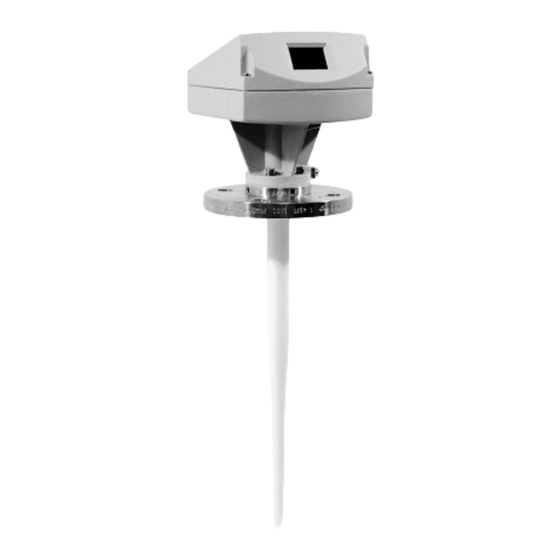
PiloTREK 2-wire
Non-contact radar level transmitter
Non-contact radar level transmitter
Non-contact radar level transmitter
Non-contact radar level transmitter
INSTALLATION
and
PROGRAMMING MANUAL
Manufacturer:
NIVELCO Control Co.
H-1043 Budapest, Dugonics u. 11.
Tel.: (36-1)-369-7575
Fax: (36-1)-369-8585
E-mail:sales@nivelco.com http://www.nivelco.com
Advertisement
Table of Contents

Related Manuals for NIVELCO PiloTREK 2-wire


Summary of Contents for NIVELCO PiloTREK 2-wire
- Page 1 PiloTREK 2-wire Non-contact radar level transmitter Non-contact radar level transmitter Non-contact radar level transmitter Non-contact radar level transmitter INSTALLATION PROGRAMMING MANUAL Manufacturer: NIVELCO Control Co. H-1043 Budapest, Dugonics u. 11. Tel.: (36-1)-369-7575 Fax: (36-1)-369-8585 E-mail:sales@nivelco.com http://www.nivelco.com...
-
Page 2: Table Of Contents
Setting the parameters………………………………………………………………………………………………………….. 8 Maintenance, error handling…………………………………………………………………………………………………..17 Safety information……………………………………………………………………………………………………………….18 Technical data……………………………………………………………………………………………………………………19 PiloTREK 2-WIRE signal converter and flange system marking codes……………………………………………….20 Conversion of Order Code to Converter- and Flange Code…………………………………………………………… 23 Parameter check list…………………………………………………………………………………………………………… 24 Installation and programming manual PiloTREK 2-wire... -
Page 3: Measurement Principle
The PiloTREK 2-WIRE level gauge is designed solely for measuring the level, distance, volume and reflection of liquids, pastes, slurries, particulate materials and solids. The PiloTREK 2-WIRE level gauge does not form part of an overfill protection system as defined in the WHG (German water pollution regulation). -
Page 4: Order Codes
NSTALLATION Most of the PiloTREK 2-WIRE versions are supplied in fully assembled condition. In this case, you may skip this chapter. However, if a device should be delivered in parts, or parts are subsequently replaced, the following should be noted. -
Page 5: Mechanical Installation
ECHANICAL INSTALLATION Hazardous-duty systems: • The PiloTREK 2-WIRE Ex is certified in conformity with European Standard for use in Zone 0, 1 and 2 hazardous locations (dependent on version). • Attention is drawn to the data and information given on the nameplate of the converter, the nameplate of the flange and the specifications in the approval certificates. - Page 6 PiloTREK 2-WIRE on the tank nozzle flange. Align PiloTREK 2- WIRE and gasket, slightly tighten nuts on stud bolts (by hand). Press shielding strip C* in the gap between tank and PiloTREK 2-WIRE flanges and secure with strap retainer S* (both items included with supply).
-
Page 7: Electrical Connection
Supply voltage at the terminals (1,2) The 4-20 mA supply must be able to provide the following voltage U at the terminals of the PiloTREK 2-WIRE – dependent on the current I. Please consider also the line resistance and possible loads on the secondary side of the supply unit. -
Page 8: Setting The Parameters
≥ 120 Ω With the program PC-CAT, version 3.01 or higher, you can configurate PiloTREK 2-WIRE instruments in a very comfortable way from a PC. Connect the non-intrinsically safe side of the isolation amplifier over a load between 120 Ω and 350 Ω to the HART adapter and connect it with a serial port of the PC. - Page 9 Tank bottom: In tanks with dished bottom, for example, the measuring signal can "disappear" if measurements are carried out near the bottom. The measured value is then automatically set to the level of the tank bottom. ▼ 6: Measurement frozen: Device is in the block distance detection (see below). Installation and programming manual PiloTREK 2-wire...
- Page 10 For distance measurement the points 0% (short distance = high level) and 100% (large distance = low level) are exchanged If no reliable measurement is possible „NO ACCESS“ is displayed. Abort by pressing ↵ Installation and programming manual PiloTREK 2-wire...
- Page 11 (compensates different wave speeds in still wells) 3.1.7 REF.OFFSET Enter -10.00...0...+10.00 [m] Reference offset is added to measured distance values. 3.1.8 TB.OFFSET Enter -100.00...0...+100.00 [m] Tank bottom offset is added to measured level values. Installation and programming manual PiloTREK 2-wire...
- Page 12 If YES, for every access a 9-digit entry code on the 4 keys is necessary. 3.4.3 CODE 1 Enter code (RRREEEUUU) Enter the entry code for access lockout. 3.4.4 LOCATION Enter text (8 characters) Enter a device identifier. Installation and programming manual PiloTREK 2-wire...
- Page 13 Tank height The tank height (Fct. 3.1.1) for the PiloTREK 2-WIRE is defined as the distance between the top edge of the tank connecting flange and the bottom reference point. The bottom reference point is that “point“ in the tank on which the microwaves of the PiloTREK 2-WIRE hit and from which they are reflected.
- Page 14 Empty-tank spectrum To enable the PiloTREK 2-WIRE to identify and blank out interference signals, e.g. caused by fixed and moving tank internals, the tank profile (empty-tank spectrum) needs to be recorded once only prior to (initial) start-up. For recording, the tank should be completely empty and all moving parts (e.g. agitators) switched on. If major interference through internals is not expected, recording of the empty-tank spectrum can also be dispensed with, since the factory has already carried out and stored a partial empty spectrum of the flange system.
- Page 15 Conversion table/Volume table A table consisting of a maximum of 50 points can be stored in the PiloTREK 2-WIRE for non-linear or linear conversion of the level, e.g. into a volumetric value. This table, however, can only be programmed with the PC-CAT program (Fct. 3.7.2).
- Page 16 Select tank type "storage tank" ↑ ↑ ↑ ↑ ↑ ↑ ↑ ↑ STORAGE T. PARAM.CHECK, Return to measurement function with confirmation of changed 5x↵ ↵ ↵ ↵ then START, parameters then meas.val. display Installation and programming manual PiloTREK 2-wire...
-
Page 17: Maintenance, Error Handling
→ , and acknowledge the errors at the end - if required - by "QUIT YES". Press key ↵ twice to return to the measuring mode. Fatal errors (FATAL ERROR), that are detected when the device is started up, render operation of the PiloTREK 2-WIRE impossible. -
Page 18: Safety Information
9. S AFETY INFORMATION Hazardous-duty systems Types of protection in the PiloTREK 2-WIRE terminal compartment: Intrinsically safe "ia" Consult the relevant wiring and installation regulations, e.g. VDE 0165, before mounting, dismantling or making electrical connections in a hazardous area Temperature rating of connecting cables:... -
Page 19: Technical Data
Wave-Stick: max. 16 bar / 232 psig, temperature-dependent according to the diagram: [psig] [bar] +232 46 - 0.3·T[°C] bar 745 - 2.42·T[°F] psig pressure temperature T +100 +150 +212 +302°F Installation and programming manual PiloTREK 2-wire... - Page 20 (delivered with 1 pc of cable gland M20x1,5 or QUICKON 2-pole cutter clamp) ® Terminals: Cable cross-section 0.5-1.5 mm² (AWG 20-16) U-clamp terminals (for PA and FE) cable cross-section max. 4 mm² (AWG 12) Installation and programming manual PiloTREK 2-wire...
-
Page 21: Pilotrek 2-Wire Signal Converter And Flange System Marking Codes
(for Hastelloy) Marking of the signal converter printed on the name plate: PT (1)(2)(3) Measuring instrument PiloTREK 2-WIRE non-contact radar level measuring instrument Ex protection code for the housing and the output signal Protection code for the housing “i” Non-Ex Ambient temperature code and safety function Standard –20…+55 °C ambient temperature and for hazardous area... - Page 22 Marking examples for signal converters : PT 263 PiloTREK 2-WIRE non-Ex version for non-hazardous area and for standard –20…+55 °C ambient temperature PT 264 PiloTREK 2-WIRE non-Ex version for non-hazardous area and for extended –40…+55 °C ambient temperature PT 251 PiloTREK 2-WIRE Ex version for hazardous area and for standard –20…+55 °C ambient temperature,...
-
Page 23: Conversion Of Order Code To Converter- And Flange Code
PiloTREK 2-wire Ex - ⌧ ⌧ ⌧ - 7 2 5 1 W x x x x with EEx i passive output and with W flange system and for standard ambient temperature with HT temperature adapter Installation and programming manual PiloTREK 2-wire... -
Page 24: Parameter Check List
13. P ARAMETER CHECK LIST PiloTREK 2-WIRE..............Vers.:..device no......Menu modified at............ :......: ......: ..... : Fct. Configuration parameters (extract) 3.1.1 Tank height........... :......: ......: ..... : 3.1.2 Block distance ..........:......: ......: ..... : 3.1.3 Antenna ............:......: ......: ..... : 3.1.4...
Need help?
Do you have a question about the PiloTREK 2-wire and is the answer not in the manual?
Questions and answers