Advertisement
Table of Contents
- 1 Table of Contents
- 2 Product Description
- 3 Basic Troubleshooting Guide
- 4 Specifications
- 5 Package Inclusion
- 6 Functions and Features
- 7 Safety Precautions
- 8 Assembly and Preparation
- 9 Control Panel Guide
- 10 Operating Guidelines
- 11 Auto Sleep Functions
- Download this manual
See also:
Instruction Manual
®
aoyue
I
2703A+
I
2703A+
NT
NT
Advanced LeadFree
Repairing System
Thank you for purchasing Aoyue Int2703A+ Repairing System.
It is important to read the manual before using the equipment.
Please keep manual in accessible place for future reference.
Manufacturer:
AOYUE TONGYI ELECTRONIC EQUIPMENT FACTORY
Jishui Industrial Zone, Nantou, Zhongshan City,
Guangdong Province, P.R.China
http://www.aoyue.com
Advertisement
Table of Contents

Related Manuals for aoyue INT 2703A+


Summary of Contents for aoyue INT 2703A+
- Page 1 ® aoyue 2703A+ I 2703A+ NT NT Advanced LeadFree Repairing System Thank you for purchasing Aoyue Int2703A+ Repairing System. It is important to read the manual before using the equipment. Please keep manual in accessible place for future reference. Manufacturer: AOYUE TONGYI ELECTRONIC EQUIPMENT FACTORY Jishui Industrial Zone, Nantou, Zhongshan City, Guangdong Province, P.R.China http://www.aoyue.com...
-
Page 2: Table Of Contents
REPLACEMENT AIR NOZZLES This manual is designed to familiarize and instruct the operator with the proper usage and maintenance of the equipment. The “Care and Safety Precautions” section explains the hazards of using any type of soldering or reworking device. Please read carefully and observe the guidelines in order to maximize usage and minimize the risk of injury or accidents . -
Page 3: Product Description
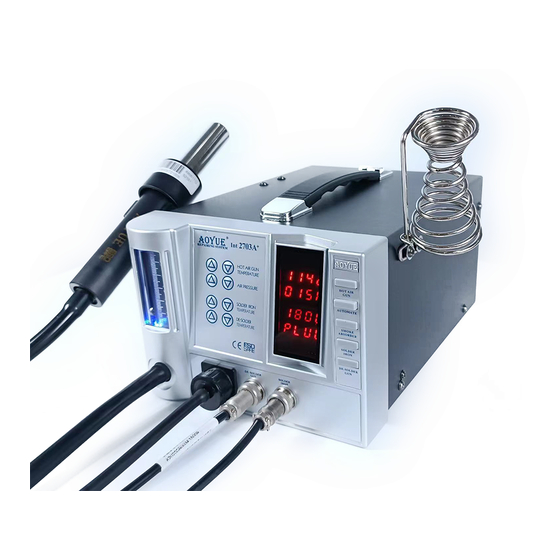
REPLACEMENT TIPS PRODUCT DESCRIPTION The Aoyue I 2703A+ Advanced LeadFree Repairing System is a reworking equipment that combines the functionality of Hot Air Gun, Soldering Iron, Smoke Absorber, and Desoldering Gun in one package. The dual port system of the Int2703A+ allows simultaneous use of the desoldering gun and soldering iron. The nozzle is specially designed with air spreader technology to disperse heat and air evenly greatly enhancing the heat output for more effective reflows. When paired with our fourth generation BGA nozzle ... -
Page 4: Specifications
SPECIFICATION BASIC TROUBLESHOOTING GUIDE Case 3: The Suction Vacuum cap is connected to the Smoke Absorber MAIN STATION Terminal or Vacuum cap instead of the Wire mesh cap. SOLUTION: Power Input : available in 110V / 220V Change the cap to the Wire mesh cap. This allows more air to pass through the system. Make sure as well that the vacuum tube of the soldering iron or Station Dimensions: 188(w) x 126(h) x 250(d) mm desoldering gun is not connected. Weight: 5.6Kg Case 4: ... -
Page 5: Package Inclusion
BASIC TROUBLESHOOTING GUIDE PACCKAGE INCLUSIONS PROBLEM 6: SOLDERING IRON TEMPERATURE DISPLAY PANEL 939 Vacuum Suction Pen SHOWS “PLUG” CHARACTERS 2703A+ Main Case 1: The system shows “PLUG” from the soldering iron temperature display panel . SOLUTION 1:Check if the soldering iron connection assembly is properly G001 IC Popper connected and secured to the receptacle on the control panel. Hot Air Gun and SOLUTION 2:Make sure the soldering iron tip is properly inserted and Hot Air Gun Holder ... -
Page 6: Functions And Features
FUNCTION and FEATURES BASIC TROUBLESHOOTING GUIDE PROBLEM 1: THE UNIT HAS NO POWER Microprocessorcontrolled ESD safe equipment. ● 1. Check if the unit is switched ON. 3in1 repairing system combining Hot Air Gun, Soldering Iron, and ● 2. Check the fuse. Replace with the same type if fuse is blown. Desoldering Gun in one sophisticated package. 3. Check the power cord and make sure there are no disconnections. Advance technology air spreader nozzle ● 4. Verify that the unit is properly connected to the power source. Digital control and display of hot air temperature, soldering iron ● temperature, desoldering gun temperature and air pressure with PROBLEM 2: HOTAIR GUN TEMPERATURE DISPLAY IS ALWAYS ... -
Page 7: Safety Precautions
CARE and MAINTENANCE SAFETY PRECAUTIONS Changing nozzle: CAUTION: Improper usage can cause serious injury to personnel ● Unscrew the securing lock and pull out the heater external housing together and/or damage to equipment. For your own safety, please observe with the securing lock, Nozzle can now be changed. Resecure nozzle by the ff. precautions. tighten the securing lock on its receptacle. Check each component after opening the package to make sure ● ... -
Page 8: Assembly And Preparation
ASSEMBL Y and PREPARATIONS CARE and MAINTENANCE 4. Inside the pipe, the quartz glass and heat insulation are installed. A. Main Station Loosen the cable and take out the heating element. As soon as the equipment has been removed from the package, 5. Insert new heating element and reconnect the terminal. Be careful not REMOVE THE SCREW located at the center of the bottom of the to rub Heating Element wire. ... -
Page 9: Control Panel Guide
CARE and MAINTENANCE CONTROL PANEL GUIDE Spare Parts Guide ® aoyue 1 Int 2703A+ Part No. Description REPAIRING SYSTEM 19 18 10094 Hot air gun heating element 2 17 30106S Plastic handle of hot air gun 3 16 S009 Hot air gun complete handle 20962 Hot air gun metal pipe 14 4 13 B012 Soldering Iron complete handle 12 5 C005 Desoldering gun heating element 3072D ... -
Page 10: Operating Guidelines
2. With all function switches deactivated and all terminal connections The external temperature sensor would now display 298 to 302. ● properly secured, switch ON the device by activating the main power switch (“10” from the control panel). Desoldering Gun Digital Temperature Calibration Example 3. The display panels, will temporarily show the product name “AOYUE The external temperature sensor displays 300 degrees. ● Int 2702” and then display “OFF”. The system will remain at this state The set temperature and displayed actual temperature of the ● until the user activates a function. ... - Page 11 DIGITAL CALIBRATION OPERATING GUIDELINES I. Utilizing the Desoldering Gun Digital Temperature Calibration 4. Adjust the air flow level using the AIR PRESSURE ADJUSTMENT 1. Turn on the Desoldering gun function switch. BUTTONS (“3” from the control panel). 2. Set to appropriate temperature you want to calibrate. Place the 5. Adjust the hot air gun air temperature using the HOT AIR GUN tip of the desoldering gun on an external temperature meter. ...
- Page 12 OPERATING GUIDELINES DIGITAL CALIBRATION C. AUTOMATE FUNCTION H. Utilizing the Solder Iron Digital Temperature Calibration The system is equipped with a 5 stage automated hot air rework By default, the system is properly calibrated but for some cases profiling system. To access and change the time and temperature when a little adjustment of the soldering iron temperature is required settings of the profile follow the guide below: ...
-
Page 13: Auto Sleep Functions
AUTO SLEEP FUNCTIONS OPERATING GUIDELINES To start the automated reworking function, Follow the guide Changing SLEEP Timer (Desoldering Gun) below: By default, the system’s sleep duration is 0 indicating the sleep 1. Ensure that the hot air gun function switch is deactivated. timer is disabled. To activate the sleep function follow the procedures. 2. Press the Hot Air Gun Automate Function Selector (“17” from the 1. ... - Page 14 OPERATING GUIDELINES AUTO SLEEP FUNCTIONS NOTES: D. SOLDERING IRON The sleep mode timer is configurable between 1 and 60 minutes. ● 1. Connect the Soldering Iron connection assembly to the 6pin A sleep mode timer value of “0” disables the sleep function. ● receptacle located at the front of the control panel (“9” from the Sleep mode settings for HotAir gun is saved into the memory and ● CONTROL PANEL GUIDE). shall remain in effect until it is reset or new data is entered. 2. Follow the initial procedures (“A. INITIAL PROCEDURES”). 3. Connect the vacuum tube to the Smoke Absorber Terminal or G. AutoSleep Mode (Soldering Iron and Desoldering Gun) ...
- Page 15 AUTO SLEEP FUNCTIONS OPERATING GUIDELINES 4. Activate the “DESOLDER GUN” Activation switch (“12” from control F. AutoSleep Mode (Hot Air Gun) panel). This will automatically start to increase the temperature of The device has a builtin autosleep mode feature such that if the the desoldering gun to 350°C (default). Hot Air Gun sits on its handle and remained idle after a certain period the 5. Adjust the desoldering gun temp. using the DESOLDER prefix of the display for Hot Air Gun air temperature will also change from ...
- Page 16 OPERATING GUIDELINES OPERATING GUIDELINES The soldering iron and desoldering gun operating temperature is ● E. Hot Air Gun Safety Feature configurable between 200°C and 480°C The systems’ hot air gun has a safety feature to limit the temperature Because of the difference in the heating element and size of the ● rise to no more than 3 degrees per second. The 3 degrees per second soldering iron tip and desoldering gun, the soldering iron will heat limit is an industry standard recommendation to minimize component up faster than the desoldering gun. This is normal and does not damage due to a rapid increase of temperature. This protection feature is have any impact on the system’s performance. activated by default and can be deactivated if desired. Below are the There will be a slight drop in temperature display once the trigger ...
Need help?
Do you have a question about the INT 2703A+ and is the answer not in the manual?
Questions and answers