Advertisement
Manufacturer:
AOYUE TONGYI ELECTRONIC EQUIPMENT FACTORY
Jishui Industrial Zone, Nantou, Zhongshan City,
Guangdong Province, P.R.China
http://www.aoyue.com
FEATURES:
●
●
●
●
●
12
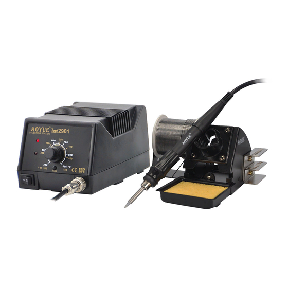
2 9 0 1
Soldering Station
INSTRUCTION MANUAL
Thank you for purchasing model 2901 Soldering Station.
Please read manual before using the unit.
Keep manual in an accessible place for future reference.
Provides higher thermal recovery performance than conventional soldering irons.
Soldering iron tip cartridges designed to slip in and out easily.
70 watts of immediate heat with unique ceramic heating element and tip
configuration.
Fast recovery, minimal heat loss, ideal for continuous production soldering and
lead free solder use.
Ergonomic, efficient and economic station anticipating future demands.
Advertisement
Table of Contents

Related Manuals for aoyue 2901


Summary of Contents for aoyue 2901
- Page 1 2 9 0 1 Soldering Station INSTRUCTION MANUAL Thank you for purchasing model 2901 Soldering Station. Please read manual before using the unit. Keep manual in an accessible place for future reference. FEATURES: ● Provides higher thermal recovery performance than conventional soldering irons. ● Soldering iron tip cartridges designed to slip in and out easily. ● 70 watts of immediate heat with unique ceramic heating element and tip configuration. ● Fast recovery, minimal heat loss, ideal for continuous production soldering and lead free solder use. ● ...
- Page 2 SOLDERING IRON TIPS WITH HEATING ELEMENT TROUBLESHOOTING GUIDE Sold Separately Before checking the inside part of the station or replacing parts, be sure to disconnect the power plug. Failure to do so may result in electric shock. CHECK: Is the power cord and/or the ● The unit does not operate when the connection plug disconnected? power switch is turned on. ACTION: Connect it. CHECK: Is the fuse blown? ACTION: Investigate why the fuse blew and then replace the fuse. If the cause can not be determined, replace the fuse. If the fuse blows again, send the unit for repair. CHECK: Is the power cord and/or the ● ...
- Page 3 MAINTENANCE ● Check the grounding 1. Unplug the power cord from the power receptacle. 2. Remove the fuse holder. 3. Replace the fuse. 4. Put the fuse holder back in place. TABLE OF CONTENTS Package Inclusion ………………………………….……….. 4 Safety Precautions ..…………………………….………….. 4 Specifications …………………………………….………….. 5 Assembly and Preparation …………………………….……. 5 Controls, Indicators & Buzzer …...…………………….……. 6 Operation …………………………………………...………… 7 Maintenance ……………………………………...………….. 8 Troubleshooting Guide ……………………………..……….. 11 10 3 ...
- Page 4 PACKAGE INCLUSION MAINTENANCE B. Checking Procedure Unless otherwise directed, carry out these procedures with the power switch OFF and the power cord UNPLUGGED. ● Check for a broken heater Verify the electrical integrity of the heater and sensor. Measure the resistance of the heater B010 Soldering Iron Power Cord 2900 Soldering Station and sensor while at room temperature. It should be 7.5 12 W. If the resistance exceeds ...
-
Page 5: Specifications
24 V High temperature shortens tip life and may cause thermal shock to components. Always use the lowest possible temperature when soldering. The excellent thermal o Solder Iron Temperature Range : C 200 480 recovery characteristics of the 2901 station ensures effective soldering at low Tip to Ground Resistance : < 2 W temperature. Tip to Ground Potential : < 2mV 2. Cleaning Always clean the soldering tip before use to remove any residual solder or flux ... - Page 6 CONTROLS, INDICATOR & BUZZER OPERATION A. Controls A. Changing the temperature setting The front panel of the soldering station has a control knob to set the temperature. 1. Turn the power ON. o 2. Adjust the control knob to set the desired temperature from 200 480 C. B. Light Indicators There are two indicators on the left side of the panel. The top one is the power Tip temperature rises quickly to desired setting. A beep sound will be heard indicator and the bottom one is the heater lamp. when desired temperature has been reached. Temperature drop is dependent on the surrounding environment and takes time to cool down. The power indicator will light when current is being supplied to the station. B. Replacing the tip The heater lamp blinks on and off when the tip temperature is reaching the set 1. Always turn the power OFF when removing or inserting a tip. ...
Need help?
Do you have a question about the 2901 and is the answer not in the manual?
Questions and answers