Table of Contents
Advertisement
Quick Links
TRANSLATION OF THE ORIGINAL COPY OF THE MANUAL
EDITION 1A-01-2011
PRONAR Sp. z o.o.
17-210 NAREW, UL. MICKIEWICZA 101A, PODLASKIE PROVINCE
tel.:
fax:
OPERATOR'S MANUAL
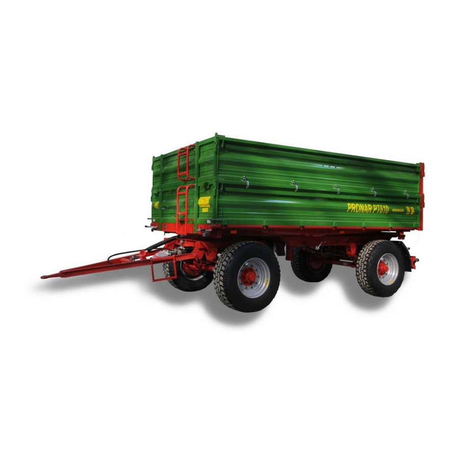
AGRICULTURAL TRAILER
PRONAR PT610
+48 085 681 63 29
+48 085 681 63 81
+48 085 681 63 83
PUBLICATION NO. 244N-00000000-UM
+48 085 681 64 29
+48 085 681 63 82
+48 085 682 71 10
www.pronar.pl
Advertisement
Table of Contents

Related Manuals for PRONAR PT610


Summary of Contents for PRONAR PT610
- Page 1 PRONAR Sp. z o.o. 17-210 NAREW, UL. MICKIEWICZA 101A, PODLASKIE PROVINCE tel.: +48 085 681 63 29 +48 085 681 64 29 +48 085 681 63 81 +48 085 681 63 82 fax: +48 085 681 63 83 +48 085 682 71 10 www.pronar.pl...
- Page 3 The machine is designed to meet obligatory standards, documents and legal regulations currently in force. The manual describes the basic safety rules and operation of agricultural trailer Pronar PT610. If the information contained in the Operator's Manual needs clarification then the user should refer for assistance to the sale point where the machine was purchased or to the Manufacturer.
- Page 4 SYMBOLS APPEARING IN THIS OPERATOR'S MANUAL Information, descriptions of danger and precautions and also recommendations and prohibitions associated with user safety instructions are marked: and also preceded by the word "DANGER”. Failure to observe the instructions may endanger the machine operator's or other person's health or life. Particularly important information and instructions, the observance of which is essential, are distinguished in the text by the sign: and also preceded by the word "IMPORTANT".
- Page 5 DIRECTIONS USED IN THIS OPERATOR'S MANUAL Left side – side to the left hand of the operator facing in the direction of machine's forward travel. Right side – side to the right hand of the operator facing in the direction of machine's forward travel.
-
Page 7: Table Of Contents
CONTENTS 1 BASIC INFORMATION IDENTIFICATION 1.1.1 TRAILER IDENTIFICATION 1.1.2 AXLE IDENTIFICATION 1.1.3 LIST OF FACTORY NUMBERS PROPER USE EQUIPMENT WARRANTY TERMS 1.10 TRANSPORT 1.11 1.5.1 TRANSPORT ON VEHICLE 1.11 1.5.2 INDEPENDENT TRANSPORT BY THE USER 1.13 ENVIRONMENTAL HAZARDS 1.14 WITHDRAWAL FROM USE 1.15 2 SAFETY ADVICE BASIC SAFETY RULES... - Page 8 3 DESIGN AND OPERATION TECHNICAL SPECIFICATION TRAILER CONSTRUCTION 3.2.1 CHASSIS 3.2.2 LOAD BOX 3.2.3 MAIN BRAKE 3.2.4 HYDRAULIC TIPPING SYSTEM 3.11 3.2.5 PARKING BRAKE 3.13 3.2.6 LIGHTING SYSTEM 3.14 4 CORRECT USE PREPARING FOR WORK BEFORE THE FIRST USE 4.1.1 CHECKING THE TRAILER AFTER DELIVERY 4.1.2 PREPARING THE TRAILER FOR THE FIRST HITCHING TO TRACTOR HITCHING AND UNHITCHING THE TRAILER FROM...
- Page 9 5.2.2 INITIAL INSPECTION OF AXLE BRAKES, 5.2.3 CHECKING BRAKE SHOE LININGS FOR WEAR 5.2.4 CHECK WHEEL AXLE BEARINGS FOR SLACKNESS 5.2.5 ADJUSTMENT OF AXLE BEARING SLACKNESS 5.2.6 MOUNTING AND DISMOUNTING WHEEL, INSPECTION OF WHEEL NUT TIGHTENING 5.2.7 CHECKING AIR PRESSURE IN TYRES, EVALUATING TECHNICAL CONDITION OF TYRES AND STEEL WHEELS 5.11 5.2.8 ADJUSTMENT OF MECHANICAL BRAKES...
- Page 10 TRAILER LUBRICATION 5.27 CONSUMABLES 5.32 5.7.1 HYDRAULIC OIL 5.32 5.7.2 LUBRICANTS 5.33 CLEANING THE TRAILER 5.33 STORAGE 5.35 5.10 TIGHTENING TORQUE FOR NUT AND BOLT CONNECTIONS 5.36 5.11 INSTALLATION AND DISASSEMBLY OF THE FRAME AND TARPAULIN COVER 5.37 5.12 INSTALLATION AND DISMOUNTING OF WALL EXTENSIONS 5.39 5.13 ADJUSTMENT OF DRAWBAR POSITION...
-
Page 11: Basic Information
SECTION BASIC INFORMATION... -
Page 12: Identification
Pronar PT610 SECTION 1 1.1 IDENTIFICATION 1.1.1 TRAILER IDENTIFICATION FIGURE 1.1 Location of the data plate and serial number (1) data plate, (2) serial number The trailer is marked with the data plate (1), and the factory number (2) located on a gold painted rectangle. -
Page 13: Axle Identification
SECTION 1 Pronar PT610 When buying the trailer check that the serial numbers on the machine agree with the number written in the WARRANTY BOOK, in the sales documents and in the OPERATOR'S MANUAL. The meanings of the individual fields found on the data plate are presented in the table below: TABLE 1.1... -
Page 14: List Of Factory Numbers
Pronar PT610 SECTION 1 FIGURE 1.2 Location of the axle data plate (1) axle, (2) data plate 1.1.3 LIST OF FACTORY NUMBERS In the event of ordering a replacement part or in the case of the appearance of problems it is often essential to give the factory numbers of parts or the VIN number of the trailer, therefore it is recommended that these numbers are inscribed in the spaces below. -
Page 15: Proper Use
SECTION 1 Pronar PT610 1.2 PROPER USE The trailer is designed for transport of harvested crops and agricultural products as well as loose and bulk materials, loads on euro pallets and pallet boxes at the farm and on public roads. It is acceptable to transport construction materials, mineral fertilisers and other loads, if fulfilling conditions indicated in section 4. - Page 16 Pronar PT610 SECTION 1 must be observed. The trailer speed must not, however, be greater than the maximum design speed of 40 km/h. Using it as intended also involves all actions connected with the safe and proper operation and maintenance of the machine. Due to the above, the user is obliged to: •...
- Page 17 SECTION 1 Pronar PT610 TABLE 1.2 Recommended types of pallets LENGTH WIDTH HEIGHT PALLET NAME - TYPE [MM] [MM] [MM] EURO pallet – standard 1 200 EURO pallet – ½ EUR pallet – extended 1 200 1 200 TABLE 1.3...
- Page 18 Pronar PT610 SECTION 1 Tractor requirements depend on trailer accessories. TABLE 1.4 Requirements for second trailer CONTENTS UNIT REQUIREMENTS Maximum gross weight 14 200 Brake system - connectors Pneumatic system 1 conduit coupler compliant with ISO 1728 Double conduit pneumatic system...
-
Page 19: Equipment
SECTION 1 Pronar PT610 1.3 EQUIPMENT TABLE 1.5 Trailer's equipment EQUIPMENT • The Operator's Manual • Warranty Book • Double conduit pneumatic system with ALB • Connection lead for the electrical system • Side pull-off mechanism • Wheel chocks Drawbar with hitching eye ∅40 mm •... -
Page 20: Warranty Terms
SECTION 1 1.4 WARRANTY TERMS PRONAR Sp. z o.o. Narew guarantees the reliable operation of the machine when it is used according to its intended purpose as described in the OPERATOR'S MANUAL. The repair period is specified in the WARRANTY BOOK. -
Page 21: Transport
SECTION 1 Pronar PT610 Demand that the seller carefully and precisely fills out the Warranty Book and warranty repair coupons. A missing date of purchase or sale point stamp may make the user ineligible for any warranty repair or refund. - Page 22 Pronar PT610 SECTION 1 technically reliable securing measures. Worn straps, cracked securing catches, bent or corroded hooks as well as elements damaged in a different way may be unsuitable for use. Carefully read the information contained in the Operator's Manual for the given securing measure.
-
Page 23: Independent Transport By The User
SECTION 1 Pronar PT610 FIGURE 1.3 Positioning of transport lugs (1) transport lug, (2) longitudinal member of upper frame, (3) longitudinal member of lower frame 1.5.2 INDEPENDENT TRANSPORT BY THE USER In the event of independent transport by the user after purchase of the trailer, the user must read the trailer Operator's Manual and adhere to the recommendations contained therein. -
Page 24: Environmental Hazards
Pronar PT610 SECTION 1 1.6 ENVIRONMENTAL HAZARDS A hydraulic oil leak constitutes a direct threat to the natural environment owing to its limited biodegradability. The negligible solubility of hydraulic oil in water does not cause extreme toxicity of organisms living in the aquatic environment. The formation of a film of oil on the water may be the direct cause of physical action on organism, perhaps causing change of oxygen values in the water because of lack of direct contact of air with the water. -
Page 25: Withdrawal From Use
SECTION 1 Pronar PT610 1.7 WITHDRAWAL FROM USE In the event of decision by the user to withdraw the trailer from use, comply with the regulations in force in the given country concerning withdrawal from use and recycling of machines withdrawn from use. Before commencing dismantling, totally remove the oil from the hydraulic system and reduce air pressure completely in the pneumatic braking system (e.g. - Page 26 Pronar PT610 SECTION 1 1.16...
-
Page 27: Safety Advice
SECTION SAFETY ADVICE... -
Page 28: Basic Safety Rules
Pronar PT610 SECTION 2 2.1 BASIC SAFETY RULES 2.1.1 USE OF TRAILER • Before using the machine, the user must carefully read this Operator's Manual and the WARRANTY BOOK. When operating the machine, the operator must comply with all recommendations contained in the Operator's Manual. -
Page 29: Hitching And Unhitching From Tractor
SECTION 2 Pronar PT610 them against falling. The above procedure should be performed by at least two persons. • In the final phase of folding the tarpaulin cover, at all times hold with one hand the top of the front frame or other permanent structural element. Non-compliance with this rule can put the user at risk of falling. -
Page 30: Hydraulic And Pneumatic Systems
Pronar PT610 SECTION 2 • Before hitching the trailer check that both machines are in good technical condition. • Be especially careful when hitching the machine. • When hitching, there must be nobody between the trailers. A person helping to hitch the trailer should stand in such a place (outside the hazard zone) where he/she is continuously visible to the tractor driver. -
Page 31: Loading And Unloading
SECTION 2 Pronar PT610 • After changing the hydraulic oil, the used oil should be properly disposed of. Used oil or oil which has lost its properties should be stored in original containers or replacement containers resistant to action of hydrocarbons. Replacement containers must be clearly marked and appropriately stored. - Page 32 Pronar PT610 SECTION 2 • When releasing the wall locks do NOT stand within reach of opened walls and the discharged load. • Keep a safe distance from overhead electric power lines during unloading and when load box is raised.
-
Page 33: Transporting The Machine
SECTION 2 Pronar PT610 with the aid of load box support. The load box may not be loaded. The trailer must be hitched to the tractor and secured with chocks and parking brake. 2.1.6 TRANSPORTING THE MACHINE • During travel on public roads comply with the road traffic regulations and transport regulations in force in a given country, in which the trailer is used. - Page 34 Pronar PT610 SECTION 2 • Before moving check that the trailer is correctly hitched to the tractor (in particular check security of hitching pin). • Do NOT move off or drive when load box is raised. • Chocks (1) should be placed only under one wheel (one in front of the wheel, the other behind the wheel - figure (2.1)).
- Page 35 SECTION 2 Pronar PT610 scattering of the load and danger while driving. The brake system is adjusted to the gross weight of the trailer. Exceeding the weight limit causes drastic reduction of the main brake force. FIGURE 2.2 Mounting place for slow-moving vehicle warning sign (1) slow-moving vehicle warning sign, (2) attachment point •...
-
Page 36: Tyres
Pronar PT610 SECTION 2 • Do NOT park trailer on slope. • When using the trailer with the middle wall extensions, there is an increased risk of loss of trailer stability, trailer overturning, failure of the trailer's structural elements, insufficient visibility of the elements of the trailer's body, uncontrolled movements of the load box on uneven terrain and the risk of overloading. - Page 37 SECTION 2 Pronar PT610 • In the event of any fault or damage, do not use the trailer until the fault has been fixed. • While performing maintenance work, use proper, close-fitting protective clothing, gloves, protective shoes, protective goggles and appropriate tools.
- Page 38 Pronar PT610 SECTION 2 • During maintenance or repair work trailer may be unhitched from tractor, but secured with chocks and parking brake. During this work the load box may not be raised. • Should it be necessary to change individual parts, use only those parts indicated by the Manufacturer.
-
Page 39: Residual Risk
2.2 RESIDUAL RISK Pronar Sp. z o. o. in Narew has made every effort to eliminate the risk of accidents. There is, however, a certain residual risk, which could lead to an accident, and this is connected mainly with the actions described below: •... -
Page 40: Information And Warning Decals
In the event of their destruction, they must be replaced with new ones. Safety decals are available from your PRONAR dealer or directly from PRONAR customer service. New assemblies, changed during repair, must be labelled once again with the appropriate safety signs. - Page 41 SECTION 2 Pronar PT610 ITEM DECAL MEANING Before beginning servicing or repairs, turn off tractor engine and remove key from ignition. Ensure that unauthorised persons do not have access to the tractor cab. Before climbing onto the trailer, switch off...
- Page 42 Pronar PT610 SECTION 2 ITEM DECAL MEANING Regularly check if the nuts and bolts fixing the wheels and other components are properly tightened. Grease the trailer according to the recommendations in the Operator's Manual Conduit supplying hydraulic brake system. Conduit supplying hydraulic tipping system.
- Page 43 SECTION 2 Pronar PT610 ITEM DECAL MEANING Manufacturer's website. – pressure value should be adapted to tyres Numbers in the Item column correspond to labels in figure (2.3) Decals – items (9) and (10) are placed on hydraulic conduits. Decal (12) is placed near the hydraulic valve.
- Page 44 Pronar PT610 SECTION 2 FIGURE 2.3 Locations of information and warning decals 2.18...
-
Page 45: Design And Operation
SECTION DESIGN AND OPERATION... -
Page 46: Technical Specification
Pronar PT610 SECTION 3 3.1 TECHNICAL SPECIFICATION TABLE 3.1 Basic technical specification of PT610 trailer CONTENTS UNIT DATA Dimensions Total length 6 720 Total width 2 550 Total height 2 520 Wheel track 1 900 Internal load box dimensions - length... -
Page 47: Trailer Construction
SECTION 3 Pronar PT610 3.2 TRAILER CONSTRUCTION 3.2.1 CHASSIS The trailer chassis consists of the subassemblies indicated in figure (3.1). Lower frame (1) is a structure welded from steel sections. The main load-bearing elements are two longitudinal members connected with each other by means of crossbars. Parking brake mechanism (10) is welded to the right longitudinal member. - Page 48 Pronar PT610 SECTION 3 FIGURE 3.1 Trailer chassis (1) lower frame, (2) tipping ram cylinder socket, (3) rear beam, (4) axle, (5) turntable frame, (6) drawbar, (7) spring catch, (8) lighting support beam, (9) front beam, (10) parking brake, (11) taper leaf spring, (12) suspension spring pins, (13) spring, (14) load box support...
-
Page 49: Load Box
SECTION 3 Pronar PT610 3.2.2 LOAD BOX The trailer's load box consists of: upper frame (1) – figure (3.2) with welded steel floor, side walls (2) front wall (4) and rear wall (5). As standard, the trailer is equipped with side wall extensions (3) of steel sheet profile and height of 600 mm, and sidewall pull-off mechanism (12) designed to provide support for closing or opening of side walls. - Page 50 Pronar PT610 SECTION 3 FIGURE 3.2 Load box (1) upper frame (2) side wall, (3) set of wall extensions, (4), front wall (5) rear wall (6) frame (7) side wall closing lever (8) rear wall stake, (9) rear wall extension stake, (10) upper hinge,...
-
Page 51: Main Brake
SECTION 3 Pronar PT610 FIGURE 3.3 Rear wall (1) valves, (2) chute (3) lever, (4) locking bolt (5) rear wall closing lever In order to enable very precise unloading of loose materials there is a slide opening placed in the rear side (1) – figure (3.3), which is raised using lever (3). When in upper position and also during transport the slide must be secured by tightening the locking screw (4). - Page 52 Pronar PT610 SECTION 3 FIGURE 3.4 Design and system diagram of double conduit pneumatic brake with automatic regulator (1) air tank, (2) control valve, (3) automatic braking force regulator, (4) pneumatic ram cylinder, (5) line connector (red), (6) line connector (yellow), (7) air filter, (8) air tank control...
- Page 53 SECTION 3 Pronar PT610 FIGURE 3.5 Design and diagram of the double conduit pneumatic braking system. (1) air tank, (2) control valve, (3) braking force regulator, (4) pneumatic cylinder, (5) conduit connector (red), (6) conduit connector (yellow), (7) air filter, (8) air tank control connector,...
- Page 54 Pronar PT610 SECTION 3 FIGURE 3.6 Design and diagram of the single conduit pneumatic braking system (1) air tank, (2) control valve, (3) manual brake force regulator, (4) pneumatic cylinder, (5) conduit connector (black), (6) air filter, (7) air tank control connector, (8) pneumatic...
-
Page 55: Hydraulic Tipping System
SECTION 3 Pronar PT610 a circuit causing the brakes to be applied when the trailer is disconnected from the tractor, see figure (3.7). When the compressed air conduit is connected to the tractor, the device automatically applying the brakes now changes its position to allow normal brake operation. - Page 56 Pronar PT610 SECTION 3 FIGURE 3.8 Hydraulic tipping system design and diagram (1) telescopic cylinder, (2) three-way valve, (3) cut-off valve, (4) quick coupler, (5) socket, (6) control cable, (7) guide roller, (8), (9) information decal The trailer system consists of two independent circuits: •...
-
Page 57: Parking Brake
SECTION 3 Pronar PT610 Three-way valve (2) – figure (3.8)is used to activate these circuits. This valve's lever can be placed in two positions: • 1 - trailer's tipping circuit opened - circuit (A), • 2 - second trailer's tipping circuit opened – circuit (B). -
Page 58: Lighting System
Pronar PT610 SECTION 3 FIGURE 3.9 Parking brake design (1) brake crank mechanism, (2) rear axle, (3) handbrake cable, L = 2 200 mm, (4) handbrake cable, L = 900 mm, (5) brake pulley block, (6) cable roller 3.2.6 LIGHTING SYSTEM The trailer electrical system is designed for supply from direct current source of 12 V. - Page 59 SECTION 3 Pronar PT610 FIGURE 3.10 Positioning of electrical components and reflective lights (1) 7-pin socket, (2) front parking light, (3) side parking light, (4) white front reflector, (5) license plate light, (6) rear left clearance light, (7) rear right clearance light, (8) rear left lamp assembly, (9) rear right lamp assembly, (10) rear triangular reflector 3.15...
- Page 60 Pronar PT610 SECTION 3 FIGURE 3.11 Electrical system diagram Marking according to table (3.2), (3.3) and (3.4) 3.16...
- Page 61 SECTION 3 Pronar PT610 TABLE 3.2 List of electrical component markings SYMBOL NAME Rear right lamp assembly Rear left lamp assembly Front seven pin socket Rear seven pin socket Right license plate light Left license plate light Front right parking light...
- Page 62 Pronar PT610 SECTION 3 TABLE 3.4 Lead colour marking MARKING COLOUR White Black Blue Orange Green Black and green Pink 3.18...
-
Page 63: Correct Use
SECTION CORRECT USE... -
Page 64: Preparing For Work Before The First Use
Pronar PT610 SECTION 4 4.1 PREPARING FOR WORK BEFORE THE FIRST USE 4.1.1 CHECKING THE TRAILER AFTER DELIVERY The manufacturer guarantees that the trailer is fully operational and has been checked according to quality control procedures and is ready for normal use. This does not release the user from an obligation to check the machine's condition after delivery and before first use. -
Page 65: Preparing The Trailer For The First Hitching To
SECTION 4 Pronar PT608 4.1.2 PREPARING THE TRAILER FOR THE FIRST HITCHING TO TRACTOR Preparation Check all the trailer's lubrication points, lubricate the machine as needed according to recommendations provided in section 5. Check if the nuts and bolts fixing the wheels are properly tightened. -
Page 66: Hitching And Unhitching The Trailer From Tractor
Pronar PT610 SECTION 4 If during test run worrying symptoms occur such as: • noise and abnormal sounds originating from the abrasion of moving elements of the trailer design, • hydraulic oil leak, • pressure drop in braking system, • incorrect operation of hydraulic and/or pneumatic cylinders, or other faults, find the cause of the problem. - Page 67 SECTION 4 Pronar PT608 Set drawbar eye or height of tractor upper transport hitch at such a height to enable hitching the trailer. Read section (5.13). Reverse tractor, hitch trailer, check coupling lock protecting machine against accidental unhitching. If the agricultural tractor is equipped with an automatic coupler, ensure that the hitching operation is completed and that drawbar eye is secured.
- Page 68 Pronar PT610 SECTION 4 During connection of braking system conduits (pneumatic double conduit) the correct sequence of conduit connection is very important. First connect the yellow connector to yellow socket in the tractor and only then connect the red connector to the red socket in the tractor.
-
Page 69: Hitching And Unhitching The Second Trailer
SECTION 4 Pronar PT608 Protect conduit ends with covers. Place conduit plugs in appropriate sockets. Disengage transport hitch and disconnect trailer drawbar from tractor hitch and drive tractor away. Place chocks under trailer wheel. Wheel chocks shall be so placed that one is in front of the wheel and the second is behind wheel of rear axle - see section 2. - Page 70 Pronar PT610 SECTION 4 Reversing tractor, drive the rear hitch (1) of the first trailer onto the drawbar of the second trailer (4). Make sure that the hitching operation was completed and the second trailer drawbar is secured. Connect conduits of pneumatic, hydraulic and electrical systems according to instructions contained in section (4.2)
-
Page 71: Loading And Securing Load
SECTION 4 Pronar PT608 Disconnecting the second trailer Immobilise tractor and trailers with parking brake. Turn off tractor engine. Ensure that unauthorised persons do not have access to the tractor cab. Disconnect lines of pneumatic, hydraulic and electrical systems according to instructions contained in section (4.2). - Page 72 Pronar PT610 SECTION 4 Due to various densities of materials, the use of the total load box capacity may lead to exceeding permissible carrying capacity of the trailer. Guideline specific weight of selected materials is given in table (4.1). Take care not to overload the trailer.
- Page 73 SECTION 4 Pronar PT608 WEIGHT BY VOLUME TYPE OF MATERIAL kg/m wet sand 1 700 – 2 050 solid bricks 1 500 – 2 100 hollow bricks 1 000 – 1 200 stones 1 500 – 2 200 soft wood...
- Page 74 Pronar PT610 SECTION 4 WEIGHT BY VOLUME TYPE OF MATERIAL kg/m baled straw (heavily crushed) 110 - 150 cereal mass in round bales 20 - 25 cut cereal mass in bulk trailer 35 - 75 cut cereal mass in gathering trailer...
- Page 75 SECTION 4 Pronar PT608 WEIGHT BY VOLUME TYPE OF MATERIAL kg/m barley 600 - 750 clover 700 - 800 grass 360 - 500 maize 700 - 850 wheat 720 - 830 oil seed rape 600 - 750 linseed 640 - 750...
- Page 76 Pronar PT610 SECTION 4 Bulk materials Loading bulk materials is normally conducted with the use of loaders or conveyors and possibly loading manually. Do not load bulk materials to a height greater than that of side walls or extensions. On completion of loading, the load should be evenly spread over the whole surface of the load box.
- Page 77 SECTION 4 Pronar PT608 condition that they are transported in the appropriate packaging and in quantities envisaged by the ADR agreement. DANGER If it is necessary to carry permitted hazardous materials, acquaint yourself with the regulations concerning transport of hazardous materials in force in the given country and also the regulations of the ADR agreement.
-
Page 78: Transporting Load
Pronar PT610 SECTION 4 Materials which may cause corrosion of steel, chemical damage or react in any other way negatively affecting the trailer structure may be transported only on condition of appropriate load preparation. Materials must be tightly packed (in plastic foil sacks, plastic containers etc.). - Page 79 SECTION 4 Pronar PT608 carrying capacity must not be exceeded as this can damage the trailer and pose a risk to the operator or other road users. • Permissible design speed and maximum speed allowed by road traffic law must not be exceeded.
-
Page 80: Unloading
Pronar PT610 SECTION 4 ATTENTION Prior to moving off with the trailer hitched, check the following: • pins connecting the load box with the lower frame are secured against falling out, • lug pins of wall extensions are secured against falling out. - Page 81 SECTION 4 Pronar PT608 Tipping pins and individual sockets are designed so it is impossible to place them on the opposite diagonal side of the load box, which would damage the trailer, FIGURE 4.2 Bolting of tipping pins (1) tipping pin, rear left or front right, (2) tipping pin, rear right or front left, (3) locking cotter...
- Page 82 Pronar PT610 SECTION 4 FIGURE 4.3 Opening the walls (1) side wall closing lever (2) rear wall closing lever (3) side wall front lock (4) side wall rear lock (5) rear wall lock after unloading, lower load box, remove the residual material from the load...
- Page 83 SECTION 4 Pronar PT608 FIGURE 4.4 Chute (1) chute slide gate, (2) chute, (3) lever, (4) locking bolt The rear load box wall is equipped with the chute slide gate (1) – figure (4.4) and chute opening (2) (additional equipment) for unloading bulk materials. Chute design allows very accurate dosing of the material to packaging (sacks, boxes etc.).
-
Page 84: Operation Of Side Wall Pull-Off Mechanism
Pronar PT610 SECTION 4 unload. Therefore, proceed cautiously and patiently. Careless operation of trailer may pose a danger to operators and bystanders can also cause damage to the machine. DANGER When closing the rear chute gate or the walls take particular care to avoid crushing fingers. - Page 85 SECTION 4 Pronar PT608 Remove lug (2) of the pull-off mechanism from side wall bolt. Replace washers and cotter pin in side wall bolt Open the side wall by means of the closure lever (7). FIGURE 4.5 Side pull-off mechanism...
-
Page 86: Proper Use And Maintenance Of Tyres
Pronar PT610 SECTION 4 4.8 PROPER USE AND MAINTENANCE OF TYRES • When working on the tyres, chocks or other objects without sharp edges should be placed under the wheels of the trailer to prevent it from rolling. Wheels can be taken off the trailer axle only when the trailer is not loaded. -
Page 87: Maintenance
SECTION MAINTENANCE... -
Page 88: Preliminary Information
Pronar PT610 SECTION 5 5.1 PRELIMINARY INFORMATION When using the trailer, regular inspections of its technical condition are essential and the performance of maintenance procedures, which keep the machine in good technical condition. In connection with this the user of the trailer is obliged to perform all the maintenance and adjustment procedures defined by the Manufacturer. -
Page 89: Initial Inspection Of Axle Brakes
SECTION 5 Pronar PT610 may be performed by specialist workshops. DANGER Do NOT use the trailer when brake system is unreliable. 5.2.2 INITIAL INSPECTION OF AXLE BRAKES, After purchasing trailer, the user is responsible for general checking of brake system of trailer axles. -
Page 90: Checking Brake Shoe Linings For Wear
Pronar PT610 SECTION 5 5.2.3 CHECKING BRAKE SHOE LININGS FOR WEAR Trailer brake shoes should be replaced when the brake lining thickness is less then the minimum specified by the manufacturer. Minimum thickness of brake shoe linings is 2 mm. -
Page 91: Check Wheel Axle Bearings For Slackness
SECTION 5 Pronar PT610 5.2.4 CHECK WHEEL AXLE BEARINGS FOR SLACKNESS FIGURE 5.2 Lifting jack support point (1) wheel axle, (2) U bolt Preparation procedures Hitch trailer to tractor, immobilize tractor with parking brake. Park tractor and trailer on hard level ground. - Page 92 Pronar PT610 SECTION 5 Checking wheel axle bearings for slackness Turning the wheel slowly in both directions check that movement is smooth and that the wheel rotates without excessive resistance. Turn the wheel so that it rotates very quickly, check that the bearing does not make any unusual sounds.
-
Page 93: Adjustment Of Axle Bearing Slackness
SECTION 5 Pronar PT610 DANGER Before commencing work, the user must read the instructions for lifting jack and adhere to the manufacturer's instructions. The lifting jack must be stably supported on the ground and so must the axle. Ensure that trailer shall not move during inspection of axle bearing slackness. -
Page 94: Wheel Nut Tightening
Pronar PT610 SECTION 5 FIGURE 5.3 Adjustment of wheel axle bearings (1) hub cover, (2) castellated nut, (3) cotter pin The wheel should turn smoothly without stiffness or detectable resistance not originating from abrasion of brake shoes in brake drum. Adjustment of bearing slackness may only be conducted when the trailer is hitched to tractor and the load box is empty. - Page 95 SECTION 5 Pronar PT610 Loosen wheel nuts according to sequence shown in figure (5.4). Place lifting jack and lift trailer. Dismount wheel. Wheel mounting Clean axle pins and nuts of contamination. Do not grease thread of nuts and pins. Check condition of pins and nuts, if necessary replace them.
- Page 96 Pronar PT610 SECTION 5 FIGURE 5.4 Sequence of nut tightening (1) - (10) sequence of nut tightening, (L) spanner length, (F) user weight Checking the wheel nut tightening: • after first use, • after first travel with load, • after travelling the first 1,000 km, •...
-
Page 97: Checking Air Pressure In Tyres, Evaluating
SECTION 5 Pronar PT610 TABLE 5.1 Spanner arm WHEEL TIGHTENING TORQUE BODY WEIGHT (F) ARM LENGTH (L) [Nm] [kg] 0.55 0.65 0.75 5.2.7 CHECKING AIR PRESSURE IN TYRES, EVALUATING TECHNICAL CONDITION OF TYRES AND STEEL WHEELS Tyre pressure should be checked each time after changing spare wheel and not less than every month. -
Page 98: Adjustment Of Mechanical Brakes
Pronar PT610 SECTION 5 Checking air pressure in tyres and visual inspection of steel wheels: • every 1 month of use, • every week during intensive work, • after changing spare wheel. 5.2.8 ADJUSTMENT OF MECHANICAL BRAKES During trailer operation drum brake linings are subjected to wear. Piston stroke extends; after exceeding the limit value, the braking force declines. - Page 99 SECTION 5 Pronar PT610 FIGURE 5.5 Adjustment of axle mechanical brakes (1) expander arm, (2) expander shaft, (3) expansion ring TABLE 5.2 Position of fork pin in expander arm PIN POSITION [mm] TYPE OF BRAKE SYSTEM FRONT AXLE REAR AXLE...
-
Page 100: Replacement Of Parking Brake Cable And Adjustment Of Cable Tension
Pronar PT610 SECTION 5 each other at full braking. If this is not so, adjust the position of the lever, which has the longer stroke. During dismantling of cylinder fork remember or mark the original setting of the cylinder fork pin (L1 distance - front axle, L2 distance - rear axle). - Page 101 SECTION 5 Pronar PT610 Adjustment of parking brake cable tension should be conducted in the event of: • stretching of cable, • loosening of parking brake cable clamps • after adjustment of axle brakes, • after repairs of axle brake system, •...
-
Page 102: Pneumatic System Maintenance
Pronar PT610 SECTION 5 After the first loading of cable, re-check the condition of cable ends, correct if necessary. FIGURE 5.7 Installation of steel cable clamps Adjustment of parking brake cable tension Hitch trailer to tractor. Park trailer and tractor on level surface. -
Page 103: Checking Air Tightness And Visual Inspection Of
SECTION 5 Pronar PT610 specialist establishments, having the appropriate technology and qualifications for this type of work. The duties of the operator connected with the pneumatic system maintenance include: • checking tightness and visual inspection of the system, • cleaning the air filter (filters), •... - Page 104 Pronar PT610 SECTION 5 Check system components by releasing brake pedal in tractor. Pay particular attention to conduit connections and brake cylinders. Repeat the system check with depressed tractor brake pedal. The help of a second person is required. In the event of the appearance of leaks, compressed air will escape at the places of damage, with a characteristic hiss.
-
Page 105: Cleaning The Air Filters
SECTION 5 Pronar PT610 5.3.3 CLEANING THE AIR FILTERS Depending on trailer working conditions, but not less than once in three months, take out and clean air filter elements, which are located in pneumatic system connection conduits. Filter elements are used many times and are not subject to change unless they are mechanically damaged. -
Page 106: Draining Water From Air Tank
Pronar PT610 SECTION 5 Hold the filter cover (2) with the other hand. After removing slide lock, the cover is pushed off by the spring located in the filter housing. The filter element and the filter body should be carefully cleaned and blown through with compressed air. -
Page 107: Cleaning The Drain Valve
SECTION 5 Pronar PT610 The compressed air in the tank causes the removal of water to the exterior. Released valve stem should automatically close and stop flow of air from the tank. If the valve stem resists returning to its position, then the whole drain valve must be unscrewed and cleaned or replaced (if it is damaged) - see section 5.3.5. -
Page 108: Cleaning And Maintaining Pneumatic Conduit
Pronar PT610 SECTION 5 5.3.6 CLEANING AND MAINTAINING PNEUMATIC CONDUIT CONNECTIONS AND PNEUMATIC SOCKETS DANGER Unreliable and dirty trailer connections may cause unreliability and faulty functioning of braking system. Damaged connection body or socket for connecting the second trailer should be replaced. In the event of damage to cover or seal, change these elements for new reliable elements. -
Page 109: Hydraulic System Maintenance
SECTION 5 Pronar PT610 Reinforcing sleeve (4) of the conduit must be thoroughly depressed. Check tightness of connections in accordance with Chapter (5.3.2). FIGURE 5.10 Installation of pneumatic conduit (1) pneumatic conduit, (2) connecting nut (3) clamping ring, (4) reinforcing sleeve 5.4 HYDRAULIC SYSTEM MAINTENANCE... -
Page 110: Checking Hydraulic System Tightness
Pronar PT610 SECTION 5 DANGER Do NOT tip trailer with unreliable hydraulic tipping system. Do NOT use the trailer if hydraulic brake system is unreliable. 5.4.2 CHECKING HYDRAULIC SYSTEM TIGHTNESS Required maintenance actions Hitch trailer to tractor. Connect all hydraulic system conduits according to maintenance instructions. -
Page 111: Couplers And Sockets
SECTION 5 Pronar PT610 5.4.3 CHECKING TECHNICAL CONDITION OF HYDRAULIC COUPLERS AND SOCKETS. Hydraulic couplers and sockets designed for connection with second trailer must be in good working condition and kept clean. Each time before connecting check if sockets in tractor or connections of second trailer are maintained in good working condition. -
Page 112: Replacement Of Bulbs
Pronar PT610 SECTION 5 • changing bulbs ATTENTION Do NOT travel with out of order lighting system. Damaged lamp lenses, and burned-out bulbs must be replaced immediately before travelling. Lost or damaged reflective lights must be replaced. Required maintenance actions Connect trailer to tractor with appropriate connection lead. -
Page 113: Trailer Lubrication
SECTION 5 Pronar PT610 TABLE 5.3 List of bulbs NUMBER BULB / QUANTITY LAMP LAMP TYPE IN 1 LAMP LAMPS R10W / 1 pc. Rear left lamp assembly WE 549L P21W / 2 pcs. R10W / 1 pc. Rear right lamp assembly WE 549P P21W / 2 pcs. - Page 114 Pronar PT610 SECTION 5 ITEM LUBRICATION POINT Chute guides Chute string pins Socket for installation of tipping ram and cylinder suspension Tipping cylinder ball bearing Front wall locking mechanism Leaf spring sliding surfaces Absorber spring pins Drawbar pins Articulated joints and sockets for installation of load box.
- Page 115 SECTION 5 Pronar PT610 Trailer lubrication should be performed with the aid of a manually or foot operated grease gun, filled with recommended grease. Before commencing work insofar as is possible remove old grease and other contamination. Remove and wipe off excess oil or grease.
- Page 116 Pronar PT610 SECTION 5 Empty grease or oil containers should be disposed of according to the recommendations of the lubricant Manufacturer. FIGURE 5.11 Trailer's lubrication points, part 1 5.30...
- Page 117 SECTION 5 Pronar PT610 FIGURE 5.12 Trailer's lubrication points, part 2 5.31...
-
Page 118: Consumables
Pronar PT610 SECTION 5 5.7 CONSUMABLES 5.7.1 HYDRAULIC OIL Always adhere to the principle that the oil in the trailer hydraulic system and in the tractor hydraulic system are of the same type. In the event of application of different types of oil make certain that both hydraulic substances may be mixed together. -
Page 119: Lubricants
SECTION 5 Pronar PT610 with the use of carbon dioxide, foam or steam extinguishers. Do not use water to quench oil fires. 5.7.2 LUBRICANTS For heavily loaded parts it is recommended to apply lithium greases with addition of molybdenum disulphide (MOS ) or graphite. - Page 120 Pronar PT610 SECTION 5 • Using pressure washer increases washing effectiveness, but particular care must be taken during work. During washing, washer nozzle may not be closer than 50 cm from the surface being cleaned. • Water temperature should not exceed 55 •...
-
Page 121: Storage
SECTION 5 Pronar PT610 should be maintained with the aid of special preparations after previous thorough washing. • After completed washing wait until the trailer is dry and then grease all inspection points according to recommendations. Remove excess oil or grease with a dry cloth. -
Page 122: Tightening Torque For Nut And Bolt
Pronar PT610 SECTION 5 5.10 TIGHTENING TORQUE FOR NUT AND BOLT CONNECTIONS Unless other tightening parameters are given, during maintenance repair work apply appropriate torque to tighten nut and bolt connections. Recommended tightening torque for the most frequently used nut and bolt connections are given in table below. Given values apply to non-lubricated steel bolts. -
Page 123: Installation And Disassembly Of The Frame And Tarpaulin Cover
SECTION 5 Pronar PT610 FIGURE 5.13 Bolt with metric thread (1) resistance class, (d) thread diameter Hydraulic conduits should be tightened using torque of 50 – 70 Nm. 5.11 INSTALLATION AND DISASSEMBLY OF THE FRAME AND TARPAULIN COVER Tarpaulin cover can only be used together with the frame. The assembly of wall extensions should be carried out with the use of appropriate platforms, ladders, ramps or other stable raised surfaces. - Page 124 Pronar PT610 SECTION 5 FIGURE 5.14 Frame with tarpaulin cover (1) front apex, (2) rear apex, (3) connecting pipe, (4) rolling beam, (5) tarpaulin cover, (6) fastening strap, (7) tarpaulin cover hook The frame structure comprises front apex (1), rear apex (2), as well as connecting pipe (3) –...
-
Page 125: Installation And Dismounting Of Wall
SECTION 5 Pronar PT610 Screw the connecting pipe (3) to the apexes (1) and (2), Place tarpaulin cover (5) so that it rests on the limiters on the right side of the trailer, Secure the tarpaulin fastening straps (6) to the tarpaulin cover hooks (7) -
Page 126: Adjustment Of Drawbar Position
Pronar PT610 SECTION 5 Dismounting of wall extensions should be performed in reverse order. DANGER Installation and dismounting of wall extensions should be carried out with the use of appropriate platforms, ladders or when standing on a ramp. These tools must be in good condition to fully protect the persons working on them against falling. -
Page 127: Troubleshooting
SECTION 5 Pronar PT610 5.14 TROUBLESHOOTING TABLE 5.8 Troubleshooting FAULT CAUSE REMEDY Brake system pneumatic Connect brake conduits. conduits not connected Applied parking brake. Release parking brake. Damaged pneumatic Replace. Problem with moving off. system connection conduits. Tighten, replace washers or seal Leaking connections. - Page 128 Pronar PT610 SECTION 5 FAULT CAUSE REMEDY Check oil quality, make sure that Improper hydraulic oil the oil in both machines is of the viscosity. same type. If necessary change oil in tractor or in trailer. Insufficient tractor hydraulic pump output, damaged Check tractor hydraulic pump.
- Page 129 NOTES …………………………………………………………………………………………………………… …………………………………………………………………………………………………………… …………………………………………………………………………………………………………… …………………………………………………………………………………………………………… …………………………………………………………………………………………………………… …………………………………………………………………………………………………………… …………………………………………………………………………………………………………… …………………………………………………………………………………………………………… …………………………………………………………………………………………………………… …………………………………………………………………………………………………………… …………………………………………………………………………………………………………… …………………………………………………………………………………………………………… …………………………………………………………………………………………………………… …………………………………………………………………………………………………………… …………………………………………………………………………………………………………… …………………………………………………………………………………………………………… …………………………………………………………………………………………………………… …………………………………………………………………………………………………………… …………………………………………………………………………………………………………… …………………………………………………………………………………………………………… …………………………………………………………………………………………………………… …………………………………………………………………………………………………………… …………………………………………………………………………………………………………… ……………………………………………………………………………………………………………...
- Page 130 …………………………………………………………………………………………………………… …………………………………………………………………………………………………………… …………………………………………………………………………………………………………… …………………………………………………………………………………………………………… …………………………………………………………………………………………………………… …………………………………………………………………………………………………………… …………………………………………………………………………………………………………… …………………………………………………………………………………………………………… …………………………………………………………………………………………………………… …………………………………………………………………………………………………………… …………………………………………………………………………………………………………… …………………………………………………………………………………………………………… …………………………………………………………………………………………………………… …………………………………………………………………………………………………………… …………………………………………………………………………………………………………… …………………………………………………………………………………………………………… …………………………………………………………………………………………………………… …………………………………………………………………………………………………………… …………………………………………………………………………………………………………… …………………………………………………………………………………………………………… …………………………………………………………………………………………………………… …………………………………………………………………………………………………………… …………………………………………………………………………………………………………… …………………………………………………………………………………………………………… …………………………………………………………………………………………………………… …………………………………………………………………………………………………………… ……………………………………………………………………………………………………………...
- Page 131 TRAILER VERSION AXLE FRONT / REAR 385/55 R22.5 160F XZA2 RE 385/55 R22.5 TL HN 809 (HA) 385/55 R22.5 TL KLS 03 (VA) PT610 385/65 R22.5 TL BU49 385/65 R22.5 TL Cargo MS 385/65 R22.5 TL TMP3000 385/65 R22.5 TL M748...
Need help?
Do you have a question about the PT610 and is the answer not in the manual?
Questions and answers