Table of Contents
Advertisement
Quick Links
Thank you for purchasing our trailer. In the interests of your
safety and care for the reliability and durability of the machine,
we ask that you familiarise yourself with the content of this
manual.
Remember!!!
Before using the trailer for the first time, check if the wheels
are properly tightened!!! Regularly check the technical
condition of the machine in accordance with the attached
schedule.
Advertisement
Table of Contents

Related Manuals for PRONAR T672


Summary of Contents for PRONAR T672
- Page 1 Thank you for purchasing our trailer. In the interests of your safety and care for the reliability and durability of the machine, we ask that you familiarise yourself with the content of this manual. Remember!!! Before using the trailer for the first time, check if the wheels are properly tightened!!! Regularly check the technical condition of the machine in accordance with the attached schedule.
-
Page 3: Manufacturer's Address
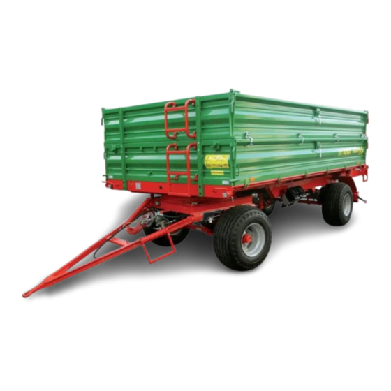
The Operator's Manual describes the basic principles of safety in use and operation of the Pronar T672 agricultural trailer, which may be produced in one of two variants: • T672 – trailer version with 500 mm sides and extensions. - Page 4 SYMBOLS APPEARING IN THIS OPERATOR'S MANUAL Information, descriptions of danger and precautions and also recommendations and prohibitions associated with user safety instructions are marked: and also preceded by the word "DANGER”. Failure to observe the instructions may endanger the machine operator's or other person's health or life. Particularly important information and instructions, the observance of which is essential, are distinguished in the text by the sign: and also preceded by the word "ATTENTION".
- Page 5 DIRECTIONS USED IN THIS OPERATOR'S MANUAL Left side – side to the left hand of the operator facing in the direction of machine's forward travel. Right side – side to the right hand of the operator facing in the direction of machine's forward travel.
-
Page 7: Table Of Contents
TABLE OF CONTENTS 1 BASIC INFORMATION IDENTIFICATION 1.1.1 TRAILER IDENTIFICATION 1.1.2 AXLE IDENTIFICATION 1.1.3 LIST OF FACTORY NUMBERS PROPER USE OPTIONAL EQUIPMENT WARRANTY TERMS TRANSPORT 1.11 1.5.1 TRANSPORT ON VEHICLE. 1.11 1.5.2 INDEPENDENT TRANSPORT BY THE USER. 1.13 ENVIRONMENTAL HAZARDS 1.14 WITHDRAWAL FROM USE 1.15... - Page 8 3 DESIGN AND OPERATION TECHNICAL SPECIFICATION TRAILER CONSTRUCTION 3.2.1 CHASSIS 3.2.2 LOAD BOX 3.2.3 MAIN BRAKE 3.2.4 HYDRAULIC TIPPER SYSTEM 3.12 3.2.5 PARKING BRAKE 3.14 3.2.6 LIGHTING SYSTEM 3.14 4 CORRECT USE PREPARING FOR WORK BEFORE FIRST USE 4.1.1 CHECKING THE TRAILER AFTER DELIVERY 4.1.2 PREPARE A TRAILER FOR FIRST HITCHING TO TRACTOR HITCHING AND DISCONNECTING FROM TRACTOR COUPLING AND UNCOUPLING SECOND TRAILER...
- Page 9 5.2.4 ADJUSTMENT OF WHEEL AXLE BEARINGS LOOSENESS 5.2.5 MOUNTING AND DISMOUNTING WHEEL, INSPECTION OF WHEEL NUT TIGHTENING. 5.2.6 CHECK AIR PRESSURE, EVALUATE TECHNICAL CONDITION OF WHEELS AND TYRES, 5.10 5.2.7 MECHANICAL BRAKES ADJUSTMENT, 5.11 5.2.8 CHANGE OF PARKING BRAKE CABLE AND ADJUSTMENT OF CABLE TENSION.
- Page 10 CLEANING TRAILER 5.33 STORAGE 5.35 5.10 TIGHTENING TORQUE FOR NUT AND BOLT CONNECTIONS 5.35 5.11 INSTALLATION AND DISASSEMBLY OF THE FRAME AND TARPAULIN COVER 5.37 5.12 INSTALLATION AND DISASSEMBLY OF EXTENSION WALLS 5.38 5.13 ADJUSTMENT OF DRAWBAR POSITION 5.39 5.14 TROUBLESHOOTING 5.40...
-
Page 11: Basic Information
SECTION BASIC INFORMATION... -
Page 12: Identification
Pronar T672 T672/1 SECTION 1 1.1 IDENTIFICATION 1.1.1 TRAILER IDENTIFICATION SZB6721XXA1X00001 PRONAR FIGURE 1.1 Location of the data plate and serial number (1) data plate, (2) serial number The trailer is marked with the data plate (1), and the factory number (2) located on a gold painted rectangle. -
Page 13: Axle Identification
SECTION 1 Pronar T672 T672/1 MANUAL. The meaning of the individual fields found on the data plate are presented in the table below: TABLE 1.1 Markings on data plate ITEM MARKING General description and purpose Symbol /Type Year of manufacture... -
Page 14: List Of Factory Numbers
Pronar T672 T672/1 SECTION 1 FIGURE 1.2 Location of the axle data plate (1) wheel axle, (2) data plate 1.1.3 LIST OF FACTORY NUMBERS In the event of ordering a replacement part or in the case of the appearance of problems it is often essential to give the factory numbers of parts or the VIN number of the trailer, therefore it is recommended that these numbers are inscribed in the spaces below. - Page 15 SECTION 1 Pronar T672 T672/1 transport construction materials, mineral fertilisers and other loads, if fulfilling conditions indicated in section 4. Non-compliance with the recommendations of the carriage and loading of goods described by the Manufacturer and the road transport regulations in force in the country in which the trailer is used, shall void the guarantee and is regarded as use of the machine not according to its intended purpose.
- Page 16 Pronar T672 T672/1 SECTION 1 • carefully read the OPERATOR'S MANUAL of the trailer and the WARRANTY BOOK and conform with the recommendations contained in these documents, • understand the trailer's operating principle and how to operate it safely and correctly, •...
- Page 17 SECTION 1 Pronar T672 T672/1 CONTENTS UNIT REQUIREMENTS Hydraulic tipper system Hydraulic oil L HL 32 Lotos Maximum system pressure bar / MPa 160 / 16 Oil demand: Electrical system Electrical system voltage Attachment socket 7 polar compliant with ISO 1724...
-
Page 18: Optional Equipment
Pronar T672 T672/1 SECTION 1 CONTENTS UNIT REQUIREMENTS Hydraulic tipper system Hydraulic oil L HL 32 Lotos Maximum system pressure bar / MPa 160 / 16 Electrical system Electrical system voltage Attachment socket 7 polar compliant with ISO 1724 Draw bar of trailer Diameter of drawbar shaft –... -
Page 19: Warranty Terms
Spare wheel holder with spare wheel 1.4 WARRANTY TERMS PRONAR Sp. z o.o., Narew guarantees the reliable operation of the machine when it is used according to its intended purpose as described in the OPERATOR'S MANUAL. The repair period is specified in the WARRANTY BOOK. - Page 20 Pronar T672 T672/1 SECTION 1 The guarantee does not apply to those parts and sub-assemblies of the machine, which are subject to wear in normal usage conditions, regardless of the warranty period. Consumables include the following parts/sub-assemblies: • drawbar hitching eye, •...
-
Page 21: Transport
SECTION 1 Pronar T672 T672/1 not. Detailed guarantee regulations are contained in the WARRANTY BOOK attached to each machine. Modification of the trailer without the written consent of the Manufacturer is forbidden. In particular, do NOT weld, drill holes in, cut or keep the main structural elements of the machine, which have a direct impact on the machine operation safety. - Page 22 Pronar T672 T672/1 SECTION 1 trailer, the construction of vehicle carrying trailer, speed of travel and other conditions. For this reason it is impossible to define the securing plan precisely. A correctly secured trailer does not change its position with regard to the transport in vehicle. The securing elements must be selected according to the guidelines of the Manufacturer of these elements.
-
Page 23: Independent Transport By The User
SECTION 1 Pronar T672 T672/1 FIGURE 1.3 Positioning of transport lugs (1) transport lug, (2) upper longitudinal frame, (3) lower longitudinal frame 1.5.2 INDEPENDENT TRANSPORT BY THE USER. In the event of independent transport by the user after purchase of the trailer, the user must read the trailer Operator's Manual and adhere to the recommendations contained therein. -
Page 24: Environmental Hazards
Pronar T672 T672/1 SECTION 1 1.6 ENVIRONMENTAL HAZARDS A hydraulic oil leak constitutes a direct threat to the natural environment owing to its limited biodegradability. Because of the low solubility of oil in water, it is not highly toxic to living organisms. -
Page 25: Withdrawal From Use
SECTION 1 Pronar T672 T672/1 1.7 WITHDRAWAL FROM USE In the event of decision by the user to withdraw the trailer from use, comply with the regulations in force in the given country concerning withdrawal from use and recycling of machines withdrawn from use. - Page 26 Pronar T672 T672/1 SECTION 1 1.16...
-
Page 27: Safety Advice
SECTION SAFETY ADVICE... -
Page 28: Basic Safety Rules
Pronar T672 T672/1 SECTION 2 2.1 BASIC SAFETY RULES 2.1.1 USE OF TRAILER • Before using the trailer, the user must carefully read this Operator's Manual and the WARRANTY BOOK. When operating the machine, the operator must comply with the recommendations. -
Page 29: Hitching And Disconnecting From Tractor
SECTION 2 Pronar T672 T672/1 them against falling. The above procedure should be performed by at least two persons. • In the final phase of folding the tarpaulin cover, at all times hold with one hand the top of the front frame or other permanent structural element. Non-compliance with this rule can put the user at risk of falling. -
Page 30: Hydraulic And Pneumatic Systems
Pronar T672 T672/1 SECTION 2 • Only machines built on a double axle chassis with permissible total weight described in table (1.3) may be hitched to the trailer. Permissible total weight of linked vehicle is dependent upon the trailer version. -
Page 31: Loading And Unloading
SECTION 2 Pronar T672 T672/1 with skin wash the area of contact with water and soap. Do NOT apply organic solvents (petrol, kerosene). • Use the hydraulic oil recommended by the Manufacturer. • After changing the hydraulic oil, the used oil should be properly disposed of. Used oil or oil, which has lost its properties, should be stored in original containers or replacement containers resistant to action of hydrocarbons. - Page 32 Pronar T672 T672/1 SECTION 2 • Ensure that during unloading / loading or raising the load box nobody is near the trailer. Before tipping load box ensure that there is visibility and make certain that there are no bystanders. • The trailer is not intended for transporting people, animals or hazardous materials.
-
Page 33: Transporting The Machine
SECTION 2 Pronar T672 T672/1 • Do NOT tip the loaded load box when the sides are closed. • Lower the load box before proceeding to deal with a malfunction. If it is necessary to raise the load box then secure it against dropping with the aid of supports. The load box may not be loaded, and the trailer must be connected to a tractor and secured with the aid of wedges and also immobilised with the parking brake. - Page 34 Pronar T672 T672/1 SECTION 2 FIGURE 2.1 Method of placing wedges (1) securing wedge, (2) wheel of rear axle • Do NOT move off or drive when load box is raised. • Prior to moving off make sure that tipping pins connecting the loadbox and the lower frame and the side wall hinge pins are secured against falling out.
- Page 35 SECTION 2 Pronar T672 T672/1 • While driving on public roads the trailer must be fitted with a certified or authorised reflective warning triangle. • Periodically drain water from the air tank in pneumatic system. During frosts, freezing water may cause damage to pneumatic system components.
-
Page 36: Tyres
Pronar T672 T672/1 SECTION 2 • If the trailer is the last vehicle in the group, a slow-moving vehicle sign should be placed on the trailer's rear load box wall – ( figure 2.2). The warning sign (1) should be attached using the specifically prepared holder (2), riveted to the rear wall of the load box. -
Page 37: Maintenance
SECTION 2 Pronar T672 T672/1 inspection should be repeated individually if a wheel has been removed from the wheel axle. • Avoid potholes, sudden manoeuvres or high speeds when turning. • Check the tyre pressure regularly. Pressure and tyres should be also checked after the whole day of intensive work. - Page 38 Pronar T672 T672/1 SECTION 2 • Before beginning work requiring raising of load box, it must be emptied and secured by supports to prevent accidental falling. The trailer must at this time be hitched to the tractor and secured with wedges and parking brake.
-
Page 39: Description Of Minimal Risk
2.2 DESCRIPTION OF MINIMAL RISK Pronar Sp. z o. o. in Narew has made every effort to eliminate the risk of accidents. There is, however, a certain minimal risk, which could lead to an accident, and this is connected mainly with the actions described below: •... -
Page 40: Information And Warning Decals
In the event of their destruction, they must be replaced with new ones. Safety decals are available from your PRONAR dealer or directly 2.14... - Page 41 SECTION 2 Pronar T672 T672/1 from PRONAR customer service. New assemblies, changed during repair, must be labelled once again with the appropriate safety signs. During trailer cleaning do not use solvents which may damage the coating of information label stickers and do not subject them to strong water jets.
- Page 42 Pronar T672 T672/1 SECTION 2 ITEM DECAL MEANING OF SYMBOL Before climbing onto the trailer, switch off tractor's engine and remove key from ignition. Caution! Danger of electric shock. Keep a safe distance from overhead electric power lines during unloading.
- Page 43 SECTION 2 Pronar T672 T672/1 ITEM DECAL MEANING OF SYMBOL Grease the trailer according to the recommendations in the Operator's Manual Conduit supplying hydraulic brake system. Conduit supplying hydraulic tipping system. Trailer carrying capacity (depends on vehicle version). Positions of control valve...
- Page 44 Pronar T672 T672/1 SECTION 2 FIGURE 2.3 Locations of information and warning decals. 2.18...
-
Page 45: Design And Operation
SECTION DESIGN AND OPERATION... -
Page 46: Technical Specification
Pronar T672 T672/1 SECTION 3 3.1 TECHNICAL SPECIFICATION TABLE 3.1 Basic technical specification CONTENTS UNIT T672 T672/1 Trailer dimensions Total length 6 455 6 455 Total width 2 390 2 390 Total height 2 243 2 500 Internal load box dimensions... -
Page 47: Trailer Construction
SECTION 3 Pronar T672 T672/1 3.2 TRAILER CONSTRUCTION 3.2.1 CHASSIS Trailer chassis consists of subassemblies indicated on figure (3.1). Lower frame (1) of the load box is a structure welded from steel sections. The main support elements are two longitudinal rails connected with crossbars. In the middle section there are sockets (2) used for mounting of the tipping ram cylinder. - Page 48 Pronar T672 T672/1 SECTION 3 FIGURE 3.1 Trailer chassis (1) lower frame, (2) tipping ram cylinder socket, (3) lighting support beam, (4) axle, (5) turntable frame, (6) drawbar, (7) spring catch, (8) rear beam, (9) front beam, (10) hitch, (11) suspension springs, (12) suspension spring pins, (13) spring, (14) load box support...
-
Page 49: Load Box
Trailer's load box consists of: upper frame (1) – figure (3.2) with welded steel floor, side walls (2) front side (3) and rear side (4). As standard, the trailer is equipped with side wall extensions of steel sheet profile and height of 500 mm (T672 trailer) or 600 mm (T672/1 trailer). - Page 50 Pronar T672 T672/1 SECTION 3 FIGURE 3.2 Load box (1) upper frame, (2) side wall, (3) front side, (4) rear side, (5) rear side stake, (6) lever of side wall closures, (7) lever, (8) rear extension stake, (9) lug, (10) linking cables, (11) cable...
-
Page 51: Main Brake
SECTION 3 Pronar T672 T672/1 In order to enable very precise unloading of loose materials there is a slide opening placed in the rear side (1) – figure (3.3), which is raised using lever (2). When in upper position and also during transport the slide must be secured by tightening the locking screw (3). - Page 52 Pronar T672 T672/1 SECTION 3 FIGURE 3.4 Double conduit pneumatic brake construction and system diagram (1) air tank, (2) control valve, (3) braking force regulator, (4) pneumatic ram cylinder, (5) conduit connector (red), (6) conduit connector (yellow), (7) air filter, (8) air tank control...
- Page 53 SECTION 3 Pronar T672 T672/1 FIGURE 3.5 Single conduit pneumatic brake construction and system diagram (1) air tank, (2) control valve, (3) brake force regulator, (4) pneumatic ram, (5) conduit connectors, (6) air filter, (7) pneumatic ram control connectors, (8) pneumatic ram piston...
- Page 54 Pronar T672 T672/1 SECTION 3 disconnected from the tractor, compare with figure (3.8). When compressed air conduit is connected to the tractor, the device automatically applying the brakes now changes its position to allow normal brake operation. FIGURE 3.6 Hydraulic brake construction and system diagram (1) hydraulic cylinder, (2) hydraulic quick coupler, (3) hydraulic socket, (4) information decal 3.10...
- Page 55 SECTION 3 Pronar T672 T672/1 FIGURE 3.7 Design and system diagram of double conduit pneumatic brake with automatic regulator (1) air tank, (2) control valve, (3) automatic braking force regulator, (4) pneumatic ram cylinder, (5) conduit connector (red), (6) conduit connector (yellow), (7) air filter, (8) air tank...
-
Page 56: Hydraulic Tipper System
Pronar T672 T672/1 SECTION 3 Three-step brake force regulator (2)- figure (3.8), adjusts braking force depending on setting. Switching to a suitable working mode is done manually by machine operator using the lever (4) prior to moving off. Three working positions are available: A - "no load”, B - "half load”... - Page 57 SECTION 3 Pronar T672 T672/1 • circuit (B) - to supply of the second trailer's hydraulic ram cylinder (if two trailers are hitched to the tractor). FIGURE 3.9 Hydraulic tipping system construction and diagram (1) telescopic cylinder, (2) three-way valve, (3) cut-off valve, (4) quick coupler, (5) socket, (6) control cable, (7) guide roller, (8), (9) information decal Three-way valve (2) –...
-
Page 58: Parking Brake
Pronar T672 T672/1 SECTION 3 • 2 - second trailer's tipping circuit opened – circuit (B). On the connection conduit, in the vicinity of socket (4) there is a decal (8) identifying the supply conduit of the hydraulic system tipping circuit. - Page 59 SECTION 3 Pronar T672 T672/1 1 2 3 4 5 6 7 8 FIGURE 3.10 Electrical system diagram Marking according to table (3.2) TABLE 3.2 List of electrical component markings SYMBOL FUNCTION Rear right light combination group Rear left light combination group...
- Page 60 Pronar T672 T672/1 SECTION 3 SYMBOL FUNCTION Left registration plate light Front right parking light Front left parking light Right clearance light Left clearance light TABLE 3.3 Marking of connections of GT and GP sockets MARKING FUNCTION Weight Power supply +12V (not used)
-
Page 61: Correct Use
SECTION CORRECT USE... -
Page 62: Preparing For Work Before First Use
Pronar T672 T672/1 SECTION 4 4.1 PREPARING FOR WORK BEFORE FIRST USE 4.1.1 CHECKING THE TRAILER AFTER DELIVERY The manufacturer guarantees that the trailer is fully operational and has been checked according to quality control procedures and is ready for normal use. This does not release the user from an obligation to check the machine's condition after delivery and before first use. -
Page 63: Prepare A Trailer For First Hitching To Tractor
SECTION 4 Pronar T672 T672/1 4.1.2 PREPARE A TRAILER FOR FIRST HITCHING TO TRACTOR Preparation Check all the trailer's lubrication points, lubricate the machine as needed according to recommendations provided in section 5. Check if the nuts and bolts fixing the wheels are properly tightened. -
Page 64: Hitching And Disconnecting From Tractor
Pronar T672 T672/1 SECTION 4 Service operation: hitching/unhitching from tractor, adjustment of draw bar position, tipping of load box etc. are described in detail in further parts of the instructions in sections 4 and 5. The trailer may be hitched only when all preparatory activities including inspection of technical condition have been completed satisfactorily. - Page 65 SECTION 4 Pronar T672 T672/1 In order to hitch the trailer to the tractor perform the actions below in the sequence presented. Machine must be immobilised by parking brake. Connection Immobilise trailer with parking brake. Pull brake mechanism to resistance in direction (A) – figure (4.1).
- Page 66 Pronar T672 T672/1 SECTION 4 Hydraulic brake system conduit is marked with information decal (10) – table (2.1). Connect main conduit supplying electric lighting system. DANGER When hitching, there must be nobody between the trailer and the tractor. When hitching the machine, tractor driver must exercise caution and make sure that nobody is present in the hazard zone.
- Page 67 SECTION 4 Pronar T672 T672/1 FIGURE 4.1 Parking brake mechanism (1) parking brake mechanism, (A), (B) crank movement direction IMPORTANT! Trailer may only be hitched to a tractor, which has the appropriate transport hitch, connection sockets for braking, hydraulic and electrical systems, and hydraulic oil in both machines is the same type and may be mixed.
-
Page 68: Coupling And Uncoupling Second Trailer
Pronar T672 T672/1 SECTION 4 Turn off tractor ignition. Ensure that unauthorised persons do not have access to the tractor cab. Disconnect all hydraulic tipping system conduits from tractor. Disconnect electric lead. Disconnect pneumatic system conduits (applies to double conduit systems): Disconnect pneumatic conduit marked red. - Page 69 SECTION 4 Pronar T672 T672/1 requires experience in driving an agricultural tractor with a trailer. It is recommended while coupling the second trailer to use the help of another person to guide the tractor driver. DANGER When hitching, there must be nobody between the trailers. Person assisting hitching up machines should stand outside the area of danger and be visible to the tractor driver at all times.
- Page 70 Pronar T672 T672/1 SECTION 4 FIGURE 4.2 Coupling second trailer ∅ (1) trailer rear hitch, (2) chain with linchpin securing pin, (3) hitch pin 40 mm, (4) drawbar of second trailer Disconnecting the second trailer Immobilise tractor and trailers with parking brake.
-
Page 71: Loading And Securing Load
SECTION 4 Pronar T672 T672/1 IMPORTANT! Do NOT hitch a second trailer constructed on any chassis except dual axle. 4.4 LOADING AND SECURING LOAD 4.4.1 GENERAL INFORMATION CONCERNING LOAD Before beginning loading make certain that the load box side walls and slide gate are properly closed and secured. - Page 72 Pronar T672 T672/1 SECTION 4 materials shown in table (4.1). It is necessary to pay particular attention not to overload the trailer. TABLE 4.1 Guideline weights volume of selected loads VOLUME WEIGHT TYPE OF MATERIAL kg/m Root crops: raw potatoes...
- Page 73 SECTION 4 Pronar T672 T672/1 VOLUME WEIGHT TYPE OF MATERIAL kg/m soft wood 300 - 450 hard sawn timber 500 - 600 impregnated timber 600 - 800 steel structures 700 – 7 000 milled burnt lime 700 - 800 cinders...
- Page 74 Pronar T672 T672/1 SECTION 4 VOLUME WEIGHT TYPE OF MATERIAL kg/m green fodder in swath 28 - 35 cut green fodder in bulk trailer 150 - 400 green fodder in gathering trailer 120 - 270 fresh beet leaves 140 - 160...
- Page 75 SECTION 4 Pronar T672 T672/1 VOLUME WEIGHT TYPE OF MATERIAL kg/m wheat 720 - 830 oil seed rape 600 - 750 linseed 640 - 750 lupins 700 - 800 oats 400 - 530 lucerne 760 - 800 640 - 760...
- Page 76 Pronar T672 T672/1 SECTION 4 Oilseed rape or seeds of other plants of very small size or powder materials can be transported provided the load box is properly sealed in places where gaps are bigger than the seed diameter or other carried material. Profiled rubber seals, silicone sealers, plastic wrap, rope or textile materials are recommended materials to provide sealing of the load box.
- Page 77 SECTION 4 Pronar T672 T672/1 DANGER If it is necessary to carry permitted hazardous materials, acquaint yourself with the regulations concerning transport of hazardous materials in force in the given country and also the regulations of the ADR agreement. It is absolutely essential to carefully read the information leaflets provided by the load manufacturer, and to observe the instructions for transporting and handling the load.
-
Page 78: Transporting Loads
Pronar T672 T672/1 SECTION 4 Materials which may cause corrosion of steel, chemical damage or react in any other way negatively affecting the trailer structure may be transported only on condition of appropriate load preparation. Materials must be tightly packed (in plastic foil sacks, plastic containers etc.). - Page 79 SECTION 4 Pronar T672 T672/1 • Before moving off make sure that there are no bystanders, especially children, near the trailer or the tractor. Take care that the driver has sufficient visibility. • Make sure that the trailer is correctly attached to the tractor and tractor's hitch is properly secured.
- Page 80 Pronar T672 T672/1 SECTION 4 a high volume load), which reduces safety. Driving near ditches or channels is dangerous as there is a risk of the wheels sliding down the slope or the slope collapsing. • Speed must be sufficiently reduced before making a turn or driving on an uneven road or a slope.
-
Page 81: Unloading
SECTION 4 Pronar T672 T672/1 4.6 UNLOADING FIGURE 4.3 Bolting tipping pins (1) tipping pin lug The trailer is equipped with hydraulic tipping system and suitable frame structure and the load box allowing tipping sideways and to the rear. Tipping of the load box is controlled from driver's cab using external tractor hydraulic system manifold. - Page 82 (4.3) – T672, the tipping pins and the sockets are designed so it is impossible to insert them on the opposite side of the loading case diagonally, which would damage the trailer) – figure (4.4) – T672/1, FIGURE 4.4 Bolting tipping pins (1) tipping pin I, (2) tipping pin II, (3) tipping pin handle 4.22...
- Page 83 Pronar T672 T672/1 a handle (3) of correctly inserted pin is directed downwards – figure (4.4); improperly inserted pins would pose the risk of damaging the trailer ) – T672/1, FIGURE 4.5 Locks of box sides and extensions (1) left wall locking lever, (2) rear wall locking lever, (3) side wall lock (rear left), (4) rear wall...
- Page 84 – figure (4.4) – T672/1. If a second trailer is hitched, it should be unloaded only when the load box of the first trailer has been lowered and the hydraulic tipping system control lever is placed in position 2 -- tipping of the second trailer.
- Page 85 SECTION 4 Pronar T672 T672/1 controlled using lever (3). In order to do that loosen the bolt interlocking slide gate (4), open the slide as required and lock again using the bolt. When unloading through the chute do not open wall locks or wall extension locks and tipping of the load box must be done very slowly and without jerking.
-
Page 86: Operation Of Side Wall Pull-Off Mechanism
Pronar T672 T672/1 SECTION 4 4.7 OPERATION OF SIDE WALL PULL-OFF MECHANISM Side wall pull-off mechanism belongs to trailer's additional equipment. Individual components are amounted to a front and side walls. Sidewall pull-off mechanism is designed to provide support for closing or opening of side walls. -
Page 87: Proper Use And Maintenance Of Tyres
SECTION 4 Pronar T672 T672/1 take out cotter pin (4), remove washers (3), Remove lug (2) of the pull-off mechanism from wall bolt. Replace washers and cotter pin in wall bolt 4.8 PROPER USE AND MAINTENANCE OF TYRES • When working on the tyres, wedges or other objects without sharp edges should be placed under the wheels of the trailer to prevent it from rolling. - Page 88 Pronar T672 T672/1 SECTION 4 4.28...
-
Page 89: Maintenance
SECTION MAINTENANCE... -
Page 90: Preliminary Information
Pronar T672 T672/1 SECTION 5 5.1 PRELIMINARY INFORMATION When using the trailer, regular inspections of its technical condition are essential and the performance of maintenance procedures, which keep the machine in good technical condition. In connection with this the user of the trailer is obliged to perform all the maintenance and adjustment procedures defined by the Manufacturer. -
Page 91: Initial Inspection Of Axle Brakes
SECTION 5 Pronar T672 T672/1 may be performed by specialist workshops. DANGER Do NOT use the trailer when brake system is unreliable. 5.2.2 INITIAL INSPECTION OF AXLE BRAKES After purchasing trailer, the user is responsible for general checking of brake system of trailer axle. -
Page 92: Check Wheel Axle Bearings Looseness
Pronar T672 T672/1 SECTION 5 5.2.3 CHECK WHEEL AXLE BEARINGS LOOSENESS FIGURE 5.1 Lifting jack support point (1) axle, (2) leaf spring shock absorber, (3) U bolt. Preparation procedures Hitch trailer to tractor, braking tractor with parking brake. Park tractor and trailer on hard level ground. - Page 93 SECTION 5 Pronar T672 T672/1 The lifting jack should be placed under the axle between U bolts (3) figure (5.1) securing axle (1) to shock absorber leaf springs (2), or as near as possible to leaf spring mounting. Recommended support points are marked with arrows.
-
Page 94: Adjustment Of Wheel Axle Bearings Looseness
Pronar T672 T672/1 SECTION 5 Check wheel axle bearings looseness • after travelling the first 1,000 km, • after intensive use of trailer, • every six months use or every 25,000 km. DANGER Before commencing work the user must read the instructions for lifting and adhere to the manufacturer's instructions. -
Page 95: Mounting And Dismounting Wheel, Inspection Of
SECTION 5 Pronar T672 T672/1 FIGURE 5.2 Adjustment of road wheel axle bearings (1) hub cover, (2) castellated nut, (3) securing split cotter pin The wheel should turn smoothly without stiffness or detectable resistance not originating from abrasion of brake shoes in brake drum. Adjustment of bearing looseness may only and exclusively be conducted, when the trailer is hitched to a tractor, and the load box is empty. - Page 96 Pronar T672 T672/1 SECTION 5 Loosen wheel nuts according to sequence given in figure (5.3). Place lifting jack and lift trailer. Dismount wheel. Mount wheel Clean axle pins and nuts of dirt contamination. Do not grease thread of nuts and pins.
- Page 97 SECTION 5 Pronar T672 T672/1 FIGURE 5.3 Sequence of tightening nuts, axles with 6 and 8 M18x1.5 pins (1) - (8) sequence of nut tightening, (L) spanner length, (F) user weight IMPORTANT! Axle nuts may not be tightened with impact wrench, because of danger of exceeding permissible tightening torque, the consequence of which may be breaking the thread connection or breaking off the hub pins.
-
Page 98: Check Air Pressure, Evaluate Technical Condition
Pronar T672 T672/1 SECTION 5 IMPORTANT! The greatest precision is achieved by use of a torque spanner. Before commencing work, ensure that correct tightening torque value is set. TABLE 5.1 Spanner arm WHEEL TIGHTENING TORQUE BODY WEIGHT (F) ARM LENGTH (L) -
Page 99: Mechanical Brakes Adjustment
SECTION 5 Pronar T672 T672/1 Tyre pressure values are specified in information decal, placed on wheel or on upper frame above trailer wheel. While checking pressure pay attention to technical condition of wheels and tyres. Look carefully at tyre sides and check the condition of tread. - Page 100 Pronar T672 T672/1 SECTION 5 Trailer wheels must brake simultaneously. Brakes adjustment involves changing the setting of the expander arm (1) (FIGURE 5.4), in relation to expander shaft (2). Required service actions Dismount cylinder fork mounted to expander arm (1).
-
Page 101: Front Axle
SECTION 5 Pronar T672 T672/1 Adjustment should be conducted separately for each wheel. Expander arm (1) should be moved by one notch in chosen direction. If the extent of cylinder action is still incorrect, move the lever again. After proper brake adjustment, at full braking the axle shaft expander should °... - Page 102 Pronar T672 T672/1 SECTION 5 Remove bolts from pulley block (7) and brake crank mechanism (1). Pull out both cables. Clean parking brake components, lubricate parking brake mechanism and pins of cable guide rollers. Install new cables (20) and (3) Install bolts and new securing cotter pins.
-
Page 103: Pneumatic System Operation
SECTION 5 Pronar T672 T672/1 Place securing wedges under trailer rear wheel. Unscrew the brake bolt mechanism maximally (1) – figure (5.5), (anti clockwise). Loosen nut (6) of cable clamps (5) of handbrake cable (2). Tighten cable and tighten clamps. -
Page 104: Inspecting And Checking Air Tightness Of
Pronar T672 T672/1 SECTION 5 • inspecting and checking air tightness of pneumatic system. • cleaning the air filter (filters), • draining water from air tank, • cleaning drain valve, • cleaning and maintaining pneumatic conduit connections, DANGER Do NOT use the trailer when brake system is unreliable. - Page 105 SECTION 5 Pronar T672 T672/1 aggressively with system components. Damaged components should be replaced or repaired. If the leaks appear in connections, the user may tighten the connections. If air continues to escape replace connection component or seal. Check system tightness •...
-
Page 106: Cleaning The Air Filters
Pronar T672 T672/1 SECTION 5 5.3.3 CLEANING THE AIR FILTERS FIGURE 5.6 Air filter (1) securing slide lock, (2) air filter cover DANGER Before proceeding to dismantle filter, reduce pressure in supply conduit. While disengaging filter slide gate, hold cover with other hand. Stand away from filter cover vertical direction. -
Page 107: Draining Water From Air Tank
SECTION 5 Pronar T672 T672/1 Hold the filter cover (2) with the other hand. After removing slide lock, the cover is pushed off by the spring, in the filter housing. The insert and the filter body should be carefully washed out and blown through with compressed air. -
Page 108: Cleaning Drain Valve
Pronar T672 T672/1 SECTION 5 FIGURE 5.7 Draining water from air tank (1) drain valve, (2) air tank, Draining water from air tank: • after each week of use. 5.3.5 CLEANING DRAIN VALVE DANGER Before dismantling drain valve release air from tank. -
Page 109: Cleaning And Maintaining Pneumatic Conduit
SECTION 5 Pronar T672 T672/1 Unscrew valve. Clean valve, purge with compressed air. Change copper seal. Screw in valve, fill air tank, and check tank tightness. Cleaning valve: • every 12 months (before winter period). 5.3.6 CLEANING AND MAINTAINING PNEUMATIC CONDUIT CONNECTIONS... -
Page 110: Hydraulic System Operation
Pronar T672 T672/1 SECTION 5 5.4 HYDRAULIC SYSTEM OPERATION 5.4.1 PRELIMINARY INFORMATION Work connected with the repair, change or regeneration of hydraulic system components (tipping cylinder, valves etc.) should be entrusted to specialist establishments, having the appropriate technology and qualifications for this type of work. -
Page 111: Checking Technical Condition Of Hydraulic
SECTION 5 Pronar T672 T672/1 of "droplets" stop using the trailer until faults are remedied. If unreliability is evident in brake cylinders do NOT use trailer with damaged system until faults are remedied. Checking tightness: • After a week of use •... -
Page 112: Operation Of Electrical System And Warning Elements
Pronar T672 T672/1 SECTION 5 5.5 OPERATION OF ELECTRICAL SYSTEM AND WARNING ELEMENTS 5.5.1 PRELIMINARY INFORMATION Work connected with the repair, change or regeneration of electrical system components should be entrusted to specialist establishments, having the appropriate technology and qualifications for this type of work. -
Page 113: Change Bulbs
SECTION 5 Pronar T672 T672/1 Before driving away make certain that all lamps and reflective lights are clean. 5.5.2 CHANGE BULBS Bulb set is presented in table (5.3). All light lenses are secured by screws and it is not necessary to dismantle whole lamp or trailer subassemblies. - Page 114 Pronar T672 T672/1 SECTION 5 FIGURE 5.8 Electrical equipment and reflective lights. (1) rear left lamp group, (2) rear right lamp group, (3) registration number illumination light, (4) 7 pole socket, (5) front parking lights, (6) white reflector light, (7) orange reflector light, (8) left clearance light (9) right clearance light (10) triangular reflector light 5.26...
-
Page 115: Trailer Lubrication
SECTION 5 Pronar T672 T672/1 5.6 TRAILER LUBRICATION TABLE 5.4 Trailer lubrication schedule ITEM LUBRICATION POINT Hub bearing Drawbar eye Expander shaft sleeve in drum hub Leaf spring shock absorbers Sockets for installation of tipping ram and cylinder suspension Tipping ram cylinder ball bearing... - Page 116 Pronar T672 T672/1 SECTION 5 ITEM LUBRICATION POINT Side extension lug Linking cable release mechanism lever pin Slide gate guides Slide gate pull shaft pins Wall pins and locks Lubrication periods – M months, D – days, – not shown in figure TABLE 5.5...
- Page 117 SECTION 5 Pronar T672 T672/1 FIGURE 5.9 Trailer's lubrication points, part 1 5.29...
- Page 118 Pronar T672 T672/1 SECTION 5 FIGURE 5.10 Trailer's lubrication points, part 2 5.30...
-
Page 119: Consumables
SECTION 5 Pronar T672 T672/1 Before beginning to grease leaf springs remove contamination, wash with water and leave to dry. Do not use pressure washers, which may cause moisture penetration between individual leaf springs. Absorber plates should be lubricated using an agent having both anticorrosion and lubricating properties, it is recommended to apply on outer leaf spring surfaces very thin layer of lithium or lime alkali grease. -
Page 120: Lubricants
Pronar T672 T672/1 SECTION 5 In the event of necessity of changing hydraulic oil for another oil, check the recommendations of the oil Manufacturer very carefully. If it is recommended to flush the system with the appropriate preparation, then comply with these recommendations. Attention should be given, so that chemical substances used for this purpose do not damage the materials of the hydraulic system. - Page 121 SECTION 5 Pronar T672 T672/1 Before starting to use greases acquaint oneself with the content off the information leaflet for the chosen product. Particularly relevant are safety rules and handling procedures for given lubricant product and waste utilisation (used containers, contaminated rags etc). Information leaflet (material safety data sheet) should be kept together with grease.
- Page 122 Pronar T672 T672/1 SECTION 5 • Surfaces smeared with oil or grease should be cleaned by application of benzene or other degreasing agents and then washed with clean water with added detergent. Comply with recommendations of the Manufacturer. DANGER Carefully read the instructions for application of washing detergents and maintenance preparations.
- Page 123 SECTION 5 Pronar T672 T672/1 5.9 STORAGE • Trailer should be kept in closed or roofed building. • If the machine will not be used for a long time, it is essential to protect it from adverse weather, especially rust and accelerated tyre deterioration. During this time trailer must be unloaded.
- Page 124 Pronar T672 T672/1 SECTION 5 TABLE 5.7 Tightening torque for nut and bolt connections 10.9 THREAD METRIC Md [Nm] 1 050 1 150 1 650 1 050 1 450 2 100 – resistance class according to DIN ISO 898 standard FIGURE 5.11...
- Page 125 SECTION 5 Pronar T672 T672/1 5.11 INSTALLATION AND DISASSEMBLY OF THE FRAME AND TARPAULIN COVER Tarpaulin cover can only be used together with the frame. The assembly of wall extensions should be carried out with the use of appropriate platforms, ladders, ramps or other stable raised surfaces.
- Page 126 Pronar T672 T672/1 SECTION 5 FIGURE 5.12 Frame with tarpaulin cover (1) front apex, (2) rear apex, (3) connecting pipe, (4) tarpaulin, (5) tensioning cable DANGER Assembly and disassembly of the frame should be carried out with the use of appropriate platforms, ladders or when standing on a ramp.
-
Page 127: Adjustment Of Drawbar Position
SECTION 5 Pronar T672 T672/1 First place upper pins of extension in appropriate rear stake locks and front walls, and after that secure base of extensions with the aid of pin lugs to upper part of side walls. Screw in extension ladder to the front wall. -
Page 128: Troubleshooting
Pronar T672 T672/1 SECTION 5 Adjustment of drawbar position is achieved by moving the spring catch (2) in chosen direction. The spring tension (1) is not changed by this operation. The spring is designed solely for maintaining the set drawbar height. In many upper transport hitch solutions of tractors it is possible to adjust its height to the hitch of the machine. - Page 129 SECTION 5 Pronar T672 T672/1 FAULT CAUSE REMEDY Check pressure on tractor pressure gauge, wait till compressor fills tank to required pressure. Damaged air compressor in Poor reliability of braking Insufficient pressure in tractor Repair or replace. system system Damaged brake valve in tractor.
- Page 130 Pronar T672 T672/1 SECTION 5 5.42...
- Page 131 NOTES …………………………………………………………………………………………………………… …………………………………………………………………………………………………………… …………………………………………………………………………………………………………… …………………………………………………………………………………………………………… …………………………………………………………………………………………………………… …………………………………………………………………………………………………………… …………………………………………………………………………………………………………… …………………………………………………………………………………………………………… …………………………………………………………………………………………………………… …………………………………………………………………………………………………………… …………………………………………………………………………………………………………… …………………………………………………………………………………………………………… …………………………………………………………………………………………………………… …………………………………………………………………………………………………………… …………………………………………………………………………………………………………… …………………………………………………………………………………………………………… …………………………………………………………………………………………………………… …………………………………………………………………………………………………………… …………………………………………………………………………………………………………… …………………………………………………………………………………………………………… …………………………………………………………………………………………………………… …………………………………………………………………………………………………………… …………………………………………………………………………………………………………… ……………………………………………………………………………………………………………...
- Page 132 …………………………………………………………………………………………………………… …………………………………………………………………………………………………………… …………………………………………………………………………………………………………… …………………………………………………………………………………………………………… …………………………………………………………………………………………………………… …………………………………………………………………………………………………………… …………………………………………………………………………………………………………… …………………………………………………………………………………………………………… …………………………………………………………………………………………………………… …………………………………………………………………………………………………………… …………………………………………………………………………………………………………… …………………………………………………………………………………………………………… …………………………………………………………………………………………………………… …………………………………………………………………………………………………………… …………………………………………………………………………………………………………… …………………………………………………………………………………………………………… …………………………………………………………………………………………………………… …………………………………………………………………………………………………………… …………………………………………………………………………………………………………… …………………………………………………………………………………………………………… …………………………………………………………………………………………………………… …………………………………………………………………………………………………………… …………………………………………………………………………………………………………… …………………………………………………………………………………………………………… …………………………………………………………………………………………………………… …………………………………………………………………………………………………………… ……………………………………………………………………………………………………………...
- Page 133 ANNEX A Tyre dimensions TRAILER VERSION AXLE FRONT / REAR 400/60-15.5 145 A8 T672 12.5/80-18,145 A8 15.0/70-18 16PR 15.0/70-18 16PR T672/1 385/55 R22.5 160F - wheel disc 13x15.5 - wheel disc 11x18 - wheel disc 13x18 - wheel disc 11.75x22.5...
Need help?
Do you have a question about the T672 and is the answer not in the manual?
Questions and answers