
Related Manuals for Rae MultiRAE Plus PGM-50/4


Summary of Contents for Rae MultiRAE Plus PGM-50/4
- Page 1 MultiRAE Plus PGM-50/4, PGM-50/4P, PGM-50/5P Multiple-Gas Monitor ANUAL 008-4022-000, Revision B, November 2003...
- Page 2 Equipment List UMBER UMBER Monitor Only Shipping case 008-3040-000 (not shown)* Monitor with wrist strap as specified Sensors as specified Rubber boot with belt clip 008-3042-000 Rechargeable Li-Ion battery 500-0037-100 Alkaline battery adapter 500-0029-000 120-230 V AC/DC wall adapter as specified Calibration adapter 008-3016-000 External filters...
- Page 3 This is a complete kit, which includes the accessories and calibration kits with a MultiRAE Plus monitor that is datalog-enabled.
- Page 4 B. Recharge batteries in non-hazardous locations. C. Do not connect external cable to serial interface jack in hazardous locations. D. Use RAE Systems Adapter P/N 500-0072 for connection to communication port and charging jack only in a non hazardous area.
- Page 5 Battery Pack Use only RAE Systems battery packs, part number 500- 0029 or 500-0037. This instrument has not been tested in an explosive gas/air atmosphere having an oxygen concentration greater than 21%. Substitution of components may impair intrinsic safety.
- Page 6 Danger Risque D’origine Electrostatique Nettoyer uniquement avec un chiffon humide. La Calibration La calibration de toute instruments de RAE Systems doit être testé en exposant l’instrument à une concentration de gaz connue par une procédure die talonnage avant de mettre en service l’instrument pour la première fois.
-
Page 7: Table Of Contents
Table of Contents General Information • 1 Dataloging-Enabled Monitors • 1 Physical Description • 1 Display • 1 Operating the MultiRAE Plus • 2 Turning the Monitor On and Off • 2 User Modes • 2 Calibrating the Monitor • 5 Getting Started •... - Page 8 Programming Mode • 19 Programming Menus • 20 Security Levels • 21 Calibrate Monitor • 22 Change Alarm Limits • 22 Change Datalog Setting • 23 Change Monitor Setup • 24 Change Sensor Configuration • 25 Correction Factors • 26 Diagnostic Mode •...
-
Page 9: General Information
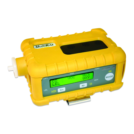
General Information The MultiRAE Plus is a programmable multiple-gas monitor designed to provide continuous exposure monitoring of toxic organic and inorganic gases, oxygen and combustible gases for workers in hazardous environments. The MultiRAE Plus is an extremely flexible one-to-five sensor instrument for use in confined space, emergency response, industrial hygiene, and many other monitoring applications. -
Page 10: Operating The Multirae Plus
90-second warm-up sequence as follows: On! – English, PGM-50 Multi-Gas Monitor, Software Version RAE Systems, Inc. (customizable using ProRAE Suite software) Monitor Type, Serial Number Date, Time, Temperature Checking Sensor ID’s (As the MultiRAE Plus checks each sensor, it displays the date it was last calibrated and its warranty expiration date. - Page 11 The table shows the features in the order in which they appear. Regardless of which user mode the monitor is in, press M to advance MODE to the next available feature. Features Text Display Advanced Mode Mode Mode Sensor Names & Instantaneous Readings - instantaneous readings are the actual gas concentrations (with...
- Page 12 Battery Voltage - the current battery voltage, measured in volts. Shut off - A fully charged battery will be 4.8 V or greater. When the battery voltage falls below 4.4 V, the “Bat” warning message appears and only 20-30 minutes of run time remain before the instrument will automatically shut down (at 4.2 V).
-
Page 13: Calibrating The Monitor
While all instruments are calibrated prior to leaving the factory, temperature extremes and/or shocks during shipment can cause sensor drift. Therefore, the accuracy of any newly purchased RAE Systems monitor should be tested by exposing the sensor(s) to known concentration calibration gas before the monitor is used or put into service. -
Page 14: Span Gas Calibration
CO, H S, LEL, Oxygen sensors. For this calibration you will need the standard RAE Systems MultiRAE Plus 4-gas calibration mix (50% LEL methane, 20.9% oxygen, 25 ppm S, 50 ppm CO in a single gas cylinder). For the calibration of other toxic sensors, or to calibrate a single sensor, please go to the Program Mode section of this manual. -
Page 15: Multiple Sensor Calibration
Calibration? CO, H S, LEL and Oxygen sensors. Press [Y/+] . TOX1 TOX2 Apply the RAE Systems 4-gas span gas mixture and start the gas flow. The 60-second countdown timer appears. TOX1 TOX2 Span Cal done! “Span Cal Done! Turn Off Gas” message Turn off Gas! appears. -
Page 16: Single Sensor Calibration
Single Sensor Calibration Press [Y/+] . TOX1 TOX2 Single Sensor When the installed sensors appear on the Calibration? display use M to move from sensor to sensor. MODE Press [Y/+] to select the highlighted sensor and start calibration. TOX1 TOX2 █OC █OC Apply span gas mixture and start gas flow. -
Page 17: Multirae Plus Usage Overview
MultiRAE Plus Usage Overview Storage Always keep the MultiRAE Plus on charge in a dry indoor area when not in use. If the MultiRAE Plus is to be stored more than 2 weeks off the charger, it is recommended to remove the Li-ion battery. Upon reinstalling the battery, it will need a complete charge and some sensors (like NO and NH ) may require time to warm up, anywhere from 20 minutes to... -
Page 18: Alarm Signals
Alarm Signals When an alarm condition occurs, the monitor will provide audible and visual alarms to alert users of unsafe conditions. Refer to the Alarm Signals table on page 11 for a complete list of alarm conditions. The alarm signals are disabled while in the following modes: Communicate with PC, Print Reading, Calibrate Monitor. - Page 19 Operating the MultiRAE Plus 11...
-
Page 20: Preset Alarm Limits And Calibration
Preset Alarm Limits and Calibration The monitor is factory calibrated with standard calibration gas and is programmed with default alarm limits as listed: Cal Gas/Balance Unit STEL High 50/Air 25/N 25/N 5/Air 10/N 20.9/N %Vol 19.5 23.5 50/Air %LEL 10/N 50/N VOC* 100/Air... -
Page 21: Datalogging
The monitor can detect any obstructions in the external filter that causes a pump stall. The alarm will activate and a “Pump” error message will appear. To acknowledge the pump stall, press [Y/+] to start the pump again. Refer to Pump Stall on page 29 for details on how to adjust the pump stall threshold for either the high or low settings. -
Page 22: Charging The Battery Pack
Charging the Battery Pack To charge the battery pack plug the transformer supplied with the monitor into the power jack on the monitor. When a Li-Ion battery pack is installed, charging automatically begins. The LED appears red during charging, and once the battery is fully charged, the LED turns green. -
Page 23: Accessories
Accessories External Filters The external filter is a PTFE (Teflon ) membrane with a 0.2 micron pore ® that reduces the amount of liquid and dust that can contaminate the sensor. Using the external filter prolongs sensor and pump life. Change the external filter whenever it becomes discolored, clogged with particles, or draws in liquid. -
Page 24: Calibration Adapter
Calibration Adapter The calibration adapter is a 6-inch Tygon tube with a male Luer connector on the end. During calibration, connect one end of the tube to the external filter (on the monitor) and the other end to the calibration gas. - Page 25 an optional open cup (P/N 007-3002-000) with calibration gas flow exceeding the pump demand, or an optional demand flow regulator (P/N 002-3051-000, female or demand flow regulator (P/N 002-3051-000, female or demand flow regulator P/N 008-3052-000, male) directly from the gas cylinder. Accessories 17...
-
Page 26: Using The Intrinsically Safe Barrier Box
Using the Intrinsically Safe Barrier Box This does NOT ship with UL/cUL-approved monitors. The barrier box is only for ATEX European approved MultiRAE monitors. To conform to ATEX European safety standard, the barrier box must be used when utilizing an RS-232 cable and/or transformer. 1. -
Page 27: Programming Mode
Programming Mode In addition to calibration, authorized users may change the monitor settings to their requirements using the Programming Mode. NOTE: Monitoring gas concentrations continues during Programming Mode, but pauses during Calibration. Datalogging also pauses during Programming Mode, but resumes when programming is finished. for desired menu Press to answer “no”... -
Page 28: Programming Menus
Programming Menus Programming Menus Sensor Name / Instantaneous Readings MODE & N/- MODE Calibrate Monitor? Fresh Air Calibration? Multiple Sensor Calibration? Single Sensor Calibration? Y/+ or N/- Modify Span Gas Value? Change LEL / VOC Span Gas? MODE Change Alarm Limits? MODE Change High Alarm Limit? Change Low Alarm Limit? -
Page 29: Security Levels
Security Levels Security levels are setup via computer using ProRAE Suite. The default password is: 0000. NOTE: For security purposes “0000” always appears instead of actual password. No changes will be saved unless the user is in the correct mode with the correct security level. -
Page 30: Calibrate Monitor
Change the type of calibration gas from methane (LEL) and isobutylene (VOC) to be used as the span gas during LEL or VOC gas calibration. However, DO NOT modify the span gases when using the RAE Systems calibration gas supplied with the monitor. -
Page 31: Change Datalog Setting
Change Datalog Setting The monitor calculates and stores the gas readings at specified intervals, which can be reviewed by the user. Users may also program additional datalog options for the monitor through the computer. Clear All Data? Erase all data stored in the non-volatile memory, but does not delete the PEAK, MIN, STEL, TWA displayed values, which are stored separately. -
Page 32: Change Monitor Setup
Change Monitor Setup Change the monitor setup or enter user information for the monitor. Use M to move the cursor from character to character. Use [Y/+] and [N/-] MODE to toggle up and down the alphabet and numbers. To save, press M MODE until “Save?”... -
Page 33: Change Sensor Configuration
Change Pump Speed? Low – (default) use when operating conditions are slow to change; prolongs pump motor life, LEL sensor life and battery run time. High – use for long lengths of tubing or when rapid changes in input conditions are expected, such as HazMat response or when used for measuring heavy, low vapor pressure compounds like jet fuel. -
Page 34: Correction Factors
Change Dilution Ratio? Attach an optional dilution fitting on the gas inlet port to dilute the gas sample. Enter a dilution ratio (from 1 to 10) to compensate the reading for the actual gas concentration. Change PID Lamp Type? This only applies to PID monitors. The PID sensor can utilize either a 10.6 eV or an 11.7eV UV. -
Page 35: Diagnostic Mode
Diagnostic Mode The monitor is equipped with a diagnostic mode that can display critical, low lever parameters to help users identify problems. Refer to Troubleshooting on page 38. The diagnostic mode allows the user to set several low level parameters which are very critical to the operation of the monitor. -
Page 36: Battery Type And Bias
To adjust the level: Turn the monitor on in diagnostic mode and go to the “Lamp = xxx, Fail = yyy +/-” display. (“xxx” is the lamp current reading; “yyy” is the value of the lamp failure threshold.) Decrease the “yyy” value until it is about 10 counts below the “xxx” value. -
Page 37: Clock, Time, Battery, And Temperature
Clock, Time, Battery, and Temperature This display shows the real time clock, the date, the battery voltage in raw count and temperature sensor reading. Sensor Expiration Date The expiration date (month and year) for each installed sensor is based on the manufacturing date and expected life of each sensor. If the current date exceeds the expiration date for any sensor, the performance of the given sensor cannot be guaranteed. -
Page 38: Maintenance
Maintenance Power from the battery is flowing to the printed circuit board (PCB) and sensors even when the power is off. Therefore, it is very important to disconnect the battery pack before servicing or replacing sensors or any components insides the monitor. Severe damage to the PCB may occur if the battery pack is not disconnected before servicing the unit. -
Page 39: Li-Ion Battery Pack
Li-Ion Battery Pack The factory supplied Li-Ion battery pack is designed to last for 10 hours of normal operation (without alarm or backlight conditions).The rechargeable batteries have a 1-year warranty. Age, ambient temperature, and heavy useage may impact battery life. Battery packs will slowly drain even if the monitor is turned off. -
Page 40: Emergency Alkaline Battery Adapter
Emergency Alkaline Battery Adapter The alkaline battery adapter supplied by RAE Systems is intrinsically safe. The adapter is intended to be used in emergency situations when there is no time to recharge the Li-Ion battery pack. The adapter accepts 4-AA alkaline batteries to provide approximately 12-14 hours of operation. -
Page 41: Sensor Replacement
Sensor Replacement Under normal operating conditions, most sensors will lose their original sensitivity after the expected operating life and eventually need to be replaced. Each sensor has a non-volatile memory that has the manufacturing and expiration dates, which appear during the warm-up period or can be looked up in the diagnostic mode. -
Page 42: Co Sensor Charcoal Filters
CO Sensor Charcoal Filters CO sensors can be sensitive to hydrocarbons. To reduce or eliminate this cross sensitivity, a charcoal filter is installed in the gas plate above the CO sensor. The charcoal filter removes organic vapor cross- sensitivity and will last 4-6 weeks under normal operation conditions before it needs to be replaced. -
Page 43: Special Bias Voltage For Toxic Gas Sensors
Special Bias Voltage for Toxic Gas Sensors NO and some NH sensors require a special high bias. The bias pins are located next to the PID sensor socket. Using the sensor puller, move the stopper block from the “OFF” pins to the “ON” pins. The sensor ID and bias voltage will be checked during the power on sequence. -
Page 44: Pid Sensor Cleaning/Replacement
Remove the stainless steel shielding cap for the PID sensor. Using the sensor puller, remove the PID sensor by carefully pulling straight out. Dip the entire PID sensor into RAE Systems’ lamp cleaning solution (supplied in the Lamp shielding cap Cleaning Kit, P/N 081-0002-000). -
Page 45: Sampling Pump Replacement
The 10.6 eV PID lamp has a 1-year warranty. The “Lamp” error is an indication of a problem with the lamp current. A dirty or contaminated sensor often causes high readings of the VOC sensor. A weak or inoperative lamp often causes low readings or no response to test gas. -
Page 46: Troubleshooting
Troubleshooting Technical Service: 1.888.723.4800 or email: Tech@raesystems.com or email: Tech@raesystems.com Problem Possible Reason(s) Possible Solution(s) Cannot turn on Defective battery. Charge or replace after charging Microprocessor hang- battery. Disconnect then battery. reconnect battery to reset computer. Otherwise, install alkaline battery pack. - Page 47 High pump Leaky inlet path. Check inlet connection. noise. Defective pump. Clean or replace pump. No inlet suction. Abnormally low Bad calibration. Low Recalibrate. Use stronger reading. sensitivity to calibration span gas. Check span gas. Wrong span value. value. Replace sensor. Bad sensor.
-
Page 48: Specifications
Specifi cations Size 4.65”L x 3.0”W x 1.9”H (11.8 x 7.6 x 4.8 cm) Weight 16 oz with battery (454g) Sensors Up to 5 sensors including: • Photo-Ionization detector for VOCs, 10.6 eV lamp standard • Protected catalytic bead for combustible gases •... -
Page 49: Range, Resolution & Response Time
0% to 95% relative humidity (non-condensing) Attachment Wrist strap and high-visibility rubber boot Warranty Lifetime on non-consuming components (per RAE Standard Warranty). 2 years for O , LEL, CO, and H sensors. 1 year all other sensors. 1 year pump, 1 year battery, 1 year for 10.6eV PID lamp. -
Page 50: Service And Repair Record
Service and Repair Record Date Service / Repair Type 42 Service and Repair Record... - Page 51 Notes...
- Page 52 Tech@raesystems.com SPECIAL NOTE: If the monitor needs to be serviced, contact either: the RAE Systems distributor where the unit was purchased; they will return the RAE Systems distributor where the unit was purchased; they will return the RAE Systems distributor monitor on the user’s behalf,...
Need help?
Do you have a question about the MultiRAE Plus PGM-50/4 and is the answer not in the manual?
Questions and answers