
Related Manuals for Rae Q-RAE


Summary of Contents for Rae Q-RAE
- Page 1 Q-RAE MULTI-GAS MONITOR OPERATION AND MAINTENANCE MANUAL (Document No.: 027-4001) Rev. B RAE SYSTEMS INC. 1339 Moffett Park Drive Sunnyvale, CA 94089 November 2001...
- Page 2 How can I be informed and updated? Be sure to mail in your warranty card via email, post or fax to get on RAE’s private database (information is never supplied to others). You will be updated on new products, technical advisory notices,...
-
Page 3: Table Of Contents
Table of Contents 1. GENERAL INFORMATION ......1-1 1.1 General Specifications ........1-2 2. OPERATION OF Q-RAE ......... 2-1 2.1 Physical Description ...........2-2 2.2 Keys and Display ..........2-4 2.3 Power On/Off............2-7 2.4 Operations............2-10 2.5 Alarm Signals ...........2-18 2.6 Backlight............2-21 2.7 Preset Alarm Limits and Calibration ....2-22 2.8 Integrated Sampling Pump........2-23... - Page 4 4.8.1 Change LEL Gas Selection......4-38 4.8.2 Enable / Disable Sensor.........4-40 4.9 Exit Programming Mode ........4-42 5. COMPUTER INTERFACE FOR Q-RAE..5-1 5.1 Install ProRAE-Suite Software......5-2 5.2 Connect Q-RAE to PC........5-4 5.3 Start ProRAE-Suite Software ......5-5 5.4 Setup Communication Port .........5-7 5.5 Processing the Configuration Data .....5-8...
- Page 5 8. TROUBLESHOOTING ........8-1 8.1 Special Diagnostic Mode ........8-2 8.2 Troubleshooting Table........8-8 APPENDIX A. QUICK REFERENCE GUIDE..A-1 APPENDIX B. CORRECTION FACTORS....B-1 APPENDIX C. Q-RAE DATA CONVERSION ® TO MICROSOFT EXCEL ....C-1 APPENDIX D. RAE TECHNICAL NOTES ....D-1 APPENDIX E. RAE APPLICATION NOTES ..E-1 APPENDIX F.
- Page 6 ! WARNING ! - DO NOT proceed before reading - This manual must be carefully read by all individuals who have or will have the responsibility for using, maintaining, or servicing this product. The product will perform as designed only if it is used, maintained, serviced accordance...
- Page 7 Special Notes When the Q-RAE monitor is taken out from the transport case and turned on for the first time, there may be some residual organic or inorganic vapors trapped inside the detector chamber. The initial toxic sensor reading may indicate a few ppm. Place the unit in an area free of organic or toxic vapors and turn on the monitor.
- Page 8 WARNINGS: Use only RAE Systems battery packs, part numbers 500-0028, 500-0029, 500-0037, or 500-0039. This instrument has not been tested in an explosive gas/air atmosphere having an oxygen concentration greater than 21%. Substitution of components may impair intrinsic safety. Recharge batteries only in non- hazardous locations.
- Page 9 ATTENTION: Pour des raisons de sécurité, cet équipment doit être utilisé, entretenu et réparé uniquement par un personnel qualifié. Étudier le manuel d’instructions en entier avant d’utiliser, d’entretenir ou de réparer l’équipement. CAUTION: Before each day’s usage, sensitivity must be tested on a known concentration of methane gas equivalent to 20- 50% of full scale concentration.
- Page 10 For maximum safety, the accuracy of the Q-RAE should be checked by exposing the sensor(s) to known concentration calibration gas before each day’s use.
-
Page 11: General Information
GENERAL INFORMATION 1. GENERAL INFORMATION Q-RAE is a programmable Multi-gas monitor designed to provide continuous exposure monitoring of oxygen, hydrogen sulfide, carbon monoxide and combustible gases for workers in hazardous environments. It monitors with two types of sensors: Combustible gases are monitored with catalytic bead sensors. -
Page 12: General Specifications
GENERAL INFORMATION 1.1 General Specifications Table 1.1 Multi-gas Monitor Specification Configuration: Pumped four-gas; datalogging option Dimensions: 4.65”L x 3.0”W x 1.9”H (11.8 cm x 7.6 cm x 4.8 cm) Weight: 16 oz (454 g) with battery. Attachment: Rubber boot, wrist strap, belt clip. Sensors: Four sensors (oxygen, combustible, hydrogen... - Page 13 GENERAL INFORMATION Multi-gas Monitor Specification (Continued) Range, Resolution and Response Time (t LEL 0-100 % 15 sec 0-30 % 0.1 % 15 sec 0-500 ppm 1 ppm 20 sec 0-100 ppm 1 ppm 30 sec Alarm: 90 dB buzzer and flashing red LED to indicate exceeded preset limits, low battery, or sensor failure.
- Page 14 GENERAL INFORMATION Multi-gas Monitor Specification (Continued) Alarm Settings: Separate alarm limit settings for TWA, STEL, Low and High alarm. Datalog Interval: Programmable 1- 3600 sec. External Alarm: Optional plug in pen size vibration alarm or earphone. Communication: Upload data to PC and Download monitor setup from PC through RS- 232 link to serial port on PC.
-
Page 15: Operation Of Q-Rae
Prior to factory shipment, the Q-RAE is preset with default alarm limits and the sensors are pre-calibrated with standard calibration gas. However, the user should calibrate the instrument before the first use. -
Page 16: Physical Description
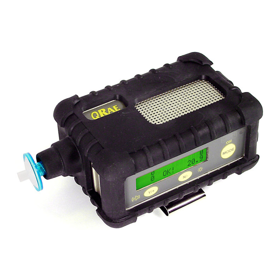
OPERATION 2.1 Physical Description Figure 2-1 shows the main components of the Q-RAE Multi-gas Monitor, which include: Gas entry port Buzzer Charge contact Serial port LCD display Wrist strap LED alarm Figure 2-1 Major parts of the Q-RAE Multi-gas Monitor •... - Page 17 OPERATION • Buzzer and red LED for alarm signal whenever the exposures exceed preset limits. • Wrist strap. • Charge contact for plugging directly to the charging station. • Gas entry port. • Serial communication port for PC interface. 2 - 3...
-
Page 18: Keys And Display
The functions of the 3 keys during normal operation are summarized in Table 2.1 on the next page: LED alarm/ charge status Light sensor 20.9 MODE [Mode] [N/-] Key [Y/+] Key Figure 2-2 Key-pad and display of the Q-RAE Multi-gas Monitor 2 - 4... - Page 19 OPERATION Table 2.1 Function in Normal Operation Turn on/off the power* and choose [MODE]: different display mode. Toggle on/off the back light. Answer as [N/-]: “No.” Alarm test and alarm acknowledgment [Y/+]: (turn off latched alarm, turn on pump or LEL sensor).
- Page 20 “Print Reading?” menu to print the reading to the RAE Printer (only shown when enabled; normally this function is disabled and not shown). • “Communicate with PC?” menu to send or receive data between PC and the Q-RAE monitor. 2 - 6...
-
Page 21: Power On/Off
After several more seconds delay, the display shows the instantaneous reading of the gas concentrations and is ready to monitor gases. To turn off the Q-RAE Multi-gas Monitor, press and hold key for 5 seconds. Monitor will beep once per [MODE] second during the power-down sequence with a count down timer showing the number of remaining seconds. - Page 22 OPERATION Turning off the Multi-gas monitor with the AC charger in place will result in a display of “Charging..” or “Battery Charged” and indication of battery voltage. This indicates that the monitor is off, but the smart charger circuit is now active.
- Page 23 OPERATION Datalogging versus Non-datalogging monitors The Q-RAE Multi-gas Monitors are available in both datalogging and non-datalogging versions. During power on sequence, a letter “D” following the version number indicates that the monitor is configured as a Datalogging monitor. Without the letter “D”, it is a Non-datalogging monitor.
-
Page 24: Operations
In the display mode, the Q-RAE Multi-gas Monitor is able to display all the information in the text mode. In addition, the following information is also available by pressing the [MODE] key: peak, minimum, STEL, TWA, run time in hours and minutes, temperature in °C, datalog... - Page 25 OPERATION The following is the detailed explanation of the displays when the [MODE] key is pressed 1) The instantaneous reading is the actual gas concentration in parts per million (ppm) for toxic gases, % of volume for oxygen and % of LEL for combustible gases.
- Page 26 OPERATION The Peak reading is the highest reading of each gas concentration since the monitor was turned on. The reading is updated at one-second intervals and is shown in the LCD display with a “Peak” message. Peak 20.9 4) The Minimum reading is the lowest reading of each gas concentration since the monitor was turned on.
- Page 27 OPERATION 6) The TWA reading is the average reading of the gas concentration times the fraction of 8 hours that the monitor has been on. TWA = Avg Reading x (Run time in hrs / 8 hrs) The reading is updated once a minute and is shown in the LCD display with “TWA”...
- Page 28 OPERATION 8) The run time reading is the accumulated “On” time in hours and minutes since the monitor was turned on. The reading is updated at one-minute intervals and is shown in the LCD display together with the current date, time and temperature. 8/3/96 8:30 On = 3:50...
- Page 29 OPERATION 12) Communicate with PC? allows the user to upload data from the Q-RAE to a Personal Computer (PC) or download configuration information from a PC to the Q-RAE. Press the [Y/+] key and the LCD displays the message “Monitor will pause, OK?” to...
- Page 30 OPERATION Displays in different user modes: See Appendix A. for more information TEXT MODE Display Instantaneous Reading & Sensor Names alternately [N]+[MODE] for 3 seconds: Password check Wrong password: back to instantaneous display Correct password: Enter Programming menu. [N]: Toggle back light [Y]: Test alarm/stop alarm [MODE] Display Battery voltage...
- Page 31 OPERATION 2. DISPLAY MODE Display Instantaneous Readings Sensor names alternately & [N]+[MODE] for 3 seconds: Password check Wrong password: back to instantaneous display Correct password: Enter Programming menu. [N]: Toggle back light [Y]: Test alarm/stop alarm [MODE] Display Peak values [MODE] Display Min values [MODE]...
-
Page 32: Alarm Signals
In addition, the Q-RAE will alarm if one of the following condition occurs: battery voltage falls below a pre-set voltage level (4.4 V), LEL sensor off, pump stall or when the datalog memory is full. - Page 33 OPERATION Alarm Signal Latching: It is possible to setup the Q-RAE from a PC or in programming mode so that when an alarm condition occurs, the alarm signals stay on even after the alarm condition is no longer present. This is called the “latching alarm”...
- Page 34 Alarm Signal Testing: Under normal non-alarm conditions, it is possible to test the Q-RAE LED, buzzer and backlight by pressing the [Y/+] key momentarily. The buzzer will beep once and the LED and back light will flash once to indicate that these alarm signals are functioning correctly.
-
Page 35: Backlight
OPERATION 2.6 Backlight The LCD display is equipped with an LED back light to assist in reading the display under poor lighting conditions. This back light can be turned on manually by pressing and holding the key for one second in normal operation. [N/-] The backlight can be turned off by pressing [N/-]... -
Page 36: Preset Alarm Limits And Calibration
OPERATION 2.7 Preset Alarm Limits and Calibration The Q-RAE Multi-gas Monitor is factory calibrated with standard calibration gas, and is programmed with default alarm limits as listed below (refer to Chapter 4 or Chapter 5 for programming procedures if new calibration or alarm limits is required). -
Page 37: Integrated Sampling Pump
OPERATION 2.8 Integrated Sampling Pump The Q-RAE Multi-gas Monitor includes an integrated sampling pump. This is a diaphragm pump providing about 250 cc per minute flow rate at the high setting. A low pump speed of about 150 cc per minute is the... -
Page 38: Datalogging
OPERATION 2.9 Datalogging The Q-RAE Multi-gas Monitor calculates and stores the gas readings based on a user-specified datalogging period and the type of measurement. Two types of gas measurements, average or peak concentration can be stored for each sensor during each datalogging interval. - Page 39 OPERATION Start/stop datalogging manually If manual datalogging mode has been selected from the normal operation menu, toggle through the menu using the key until the “Start Datalog?” prompt is [MODE] displayed. Pressing the [Y/+] key turns on datalogging. key while “Stop Datalog?” Likewise, pressing the [Y/+] is being displayed, turns off datalogging.
-
Page 41: Operation Of Accessories
OPERATION OF ACCESSORIES 3. OPERATION OF ACCESSORIES The accessories for Q-RAE include: • Battery charger • Alkaline battery adapter • Water trap filter and remote sampling probe • Dilution fitting • Calibration adapter WARNING: To reduce the risk of ignition of hazardous atmospheres, recharge battery only in areas known to be non-hazardous. -
Page 42: Battery Charging Operation
OPERATION OF ACCESSORIES 3.1 Battery Charging Operation The charging circuit of the Q-RAE is built into the monitor. It only needs a regular AC to 12 V DC adapter (wall mount transformer) to charge the monitor. 1. Connect the AC adapter (or the optional automotive charging adapter) to the DC jack on the Q-RAE monitor. - Page 43 Deep Discharge? battery will begin a deep discharge followed by a charge cycle. Note 3: The latest version of the Q-RAE monitor has a smart charging circuitry and algorithm. It may be left connected to the charger indefinitely without damaging the battery.
-
Page 44: Alkaline Battery Adapter
OPERATION OF ACCESSORIES 3.2 Alkaline Battery Adapter An alkaline battery adapter is supplied with each Q-RAE kit. It accepts four AA size alkaline batteries and can be used in place of the NiCd battery pack to provide approximately 12-14 hours of operation. The adapter is... -
Page 45: Water Trap Filter
OPERATION OF ACCESSORIES 3.3 Water Trap Filter ® The water trap filter is made of PTFE (Teflon ) membrane with a 0.2 micron pore size to prevent liquid water from being sucked into the sensor manifold, which would cause extensive damage to the monitor. It will also prevent any dust from entering the monitor and will prolong the operating life of the sensors and the pump. -
Page 46: Remote Sampling Probe Or Tygon Tubing
OPERATION OF ACCESSORIES 3.4 Remote Sampling Probe or Tygon Tubing An optional 6-foot Teflon remote sampling probe with a telescoping handle or 15-foot Tygon tubing are handy accessories for users to probe areas that are difficult to reach, such as ceilings, storage tanks, underground man- holes, etc. -
Page 47: Dilution Fitting
OPERATION OF ACCESSORIES 3.5 Dilution Fitting An optional dilution fitting can be installed together with the remote sampling probe or Tygon tubing on the gas inlet port to dilute the gas samples. This fitting is needed if the gas sample does not contain more than 15% of oxygen. This is due to the fact that the combustible sensor will not function correctly when the oxygen concentration falls below 15%. -
Page 48: Calibration Adapter
Luer connector. For calibration, simply connect the Luer adapter to the water trap filter on the Q- RAE monitor and the open Tygon or Teflon tubing to the metal adapter from the calibration gas regulator. Teflon adapter can also be used as a sampling probe during normal operation, and is preferred for LEL measurements of less-volatile compounds. -
Page 49: Programming Of Q-Rae
PROGRAMMING 4. PROGRAMMING OF Q-RAE The Q-RAE Monitor is built with a microcomputer to provide programming flexibility for the user. Authorized users can re-calibrate the monitor, change the alarm limits, change site ID, user ID, datalogging period, real time clock, etc. -
Page 50: Programming Mode
PROGRAMMING 4.1 Programming Mode The Q-RAE has three user modes: text, display and programming mode. user access programming function only if the unit is in the programming mode (or from text mode with a password). If the monitor is set to display mode, the user cannot enter the programming menu. - Page 51 PROGRAMMING Security Level There are three levels of security in the Q-RAE programming mode to provide further protection against unauthorized changes to the monitor alarm settings and other settings. Level 2 security allows a user to enter programming mode without any restrictions. This is the default security setting.
-
Page 52: Keys For Programming Mode
PROGRAMMING 4.2 Keys for Programming Mode The three keys perform a different set of functions during the programming mode as summarized below. Table 4.2 Function in Programming Menu Exit menu when press momentarily or [MODE]: exit data entry mode when pressed and held for 1 second [Y/+]: Increase numerical value for data entry... - Page 53 PROGRAMMING 4.3 Entering the Programming Menu 1. Turn on the Q-RAE monitor (refer to Section 2.3 for the power on sequence). 2. Press and hold down both keys for [MODE] [N/-] three seconds to enter programming mode. Note: This is to prevent a user from entering the programming mode by accident.
- Page 54 PROGRAMMING 6. Repeat Step 5 until all four digits are entered. Press and hold for one second. [MODE] 7. If the entered password is correct, the monitor enters the programming menu. The first menu item “Calibrate Monitor?” is displayed. 8. If the password is incorrect, the display shows “Wrong Password???”...
-
Page 55: Calibration Of Q-Rae Monitor
For maximum safety, the accuracy of the Q-RAE should be checked by exposing the sensor(s) to known concentration calibration gas before each day’s use. - Page 56 PROGRAMMING Q-RAE monitors can be calibrated either with gas from a gas sample bag (Tedlar® bag), directly from a gas bottle using a demand-flow type regulator, or from an open-tube (also open cup or Tee) that allows excess gas to escape past the inlet probe.
-
Page 57: Fresh Air Calibration
[Y/+] menu shows: “Fresh Air Calibration?” 2. If the “fresh” air bottle is available, twist the Luer calibration adapter onto the inlet port of the Q-RAE Monitor and connect the other end of the tube to the fresh gas bottle. -
Page 58: Multiple Sensor Calibration
PROGRAMMING 4.4.2 Multiple Sensor Calibration This function simultaneously determines the second point of calibration curves for multiple sensors in the monitor. A four-gas mix (Typically CH , CO, H S, O , balance N is needed to perform this procedure. Connect the monitor to the sample bag filled with mixed gas as shown in Figure 4-1. - Page 59 4. Turn off the flow of gas. Disconnect the calibration adapter from the Q-RAE Monitor. 5. If the sensor failed the calibration, the sensor name and an error message “failed, continue?” will appear. Press the [N/-] or [MODE] key to abort the calibration and move directly to the next sub-menu item.
- Page 60 PROGRAMMING 7. Press the [MODE] key momentarily to move from one sensor location to the next one. Repeat Step 7 until all of the sensors, which need to be calibrated during multiple sensor calibration, are selected. Press and hold the [MODE] key for 1 second to save the new sensor selection.
-
Page 61: Single Sensor Calibration
PROGRAMMING 4.4.3 Single Sensor Calibration This procedure determines the second point of the sensor calibration curve for a single sensor. A standard reference gas (span gas) is needed to perform this procedure. Table 2.2 shows the standard calibration gas that is typically used as the span gas in the factory. - Page 62 4. Turn off the flow of gas. Disconnect the calibration adapter from the Q-RAE Monitor. 5. Repeat Step 1 to Step 4 to calibrate the next sensor. 6. Press...
- Page 63 PROGRAMMING Oxygen Sensor Calibration The oxygen sensor calibration is slightly different from all other sensors. The oxygen sensor measures a range from 0 to 30% of oxygen in the air. During “fresh” air calibration, the oxygen sensor is calibrated to a pre-programmed value of 20.9% by volume oxygen.
-
Page 64: Modify Span Gas Value
PROGRAMMING 4.4.4 Modify Span Gas Value This function allows the user to change the span values of the standard calibration gases. 1. “Modify Span Gas Value?” is the next sub-menu item in Table 4.3. 2. Press the [Y/+] key. The display shows: span 20.9 A cursor is blinking at the first digit of the first span... -
Page 65: Change Lel Span Gas
PROGRAMMING 4.4.5 Change LEL Span Gas This function allows the user to select a specific LEL gas to be used as the span gas during LEL gas calibration. 1. “Change LEL Span Gas?” is the next sub-menu item in Table 4.3. 2. -
Page 66: Change Alarm Limits
PROGRAMMING Change Alarm Limits In the programming mode, the users may change alarm limits of each sensor for the Q-RAE Monitor. Table 4.4 shows the sub-menus for changing the alarm limits. Table 4.4 Alarm Limit Sub-Menu Change High Alarm limit? - Page 67 PROGRAMMING STEL To modify this limit, starting from the left-most digit, use the [Y/+] [N/-] key to change the digit value and press the [MODE] key momentarily to advance to the next digit. The flashing digit will move on to the next digit to its right.
-
Page 68: View Or Change Datalog
PROGRAMMING 4.6 View or Change Datalog Q-RAE monitor calculates and stores the gas readings at a specified interval. The user can review these stored readings or change datalog setup from the programming mode. Users can also program additional datalog options in PC and downloaded them to the monitor (see Section 5.0... -
Page 69: Reset Peak And Minimum
PROGRAMMING 4.6.1 Reset Peak and Minimum This function will reset peak and minimum data stored in the non-volatile data memory. 1. “Reset Peak and Minimum?” is the first sub-menu item in Table 4.5. 2. Press the [Y/+] key to clear the peak and minimum data memory. -
Page 70: Clear All Data
PROGRAMMING 4.6.2 Clear All Data This function erases all data stored in the non-volatile data memory. It does not change STEL, TWA, Peak, minimum concentration or run time values which are stored in the other location. 1. “Clear All Data?” is the next sub-menu item in Table 4.5. -
Page 71: Change Datalog Period
PROGRAMMING 4.6.3 Change Datalog Period The datalog period can be programmed from 1 to 3,600 seconds (1 hour). 1. “Change Datalog Period?” is the next sub-menu item in Table 4.5. 2. Press the key, the display shows “New Period = [Y/+] 0060”... -
Page 72: Select Data Type
PROGRAMMING 4.6.4 Select Data Type The user can choose to store either the average or the peak value during each datalog period. 1. “Select Data Type?” is the next sub-menu item in Table 4.5. 2. Press the key, the display shows the current data [Y/+] type: “Data Type = Average?”... -
Page 73: View Datalog
PROGRAMMING 4.6.5 View Datalog This function allows the user to review all the data that is stored in the non-volatile data memory. 1. “View Datalog?” is the next sub-menu item in Table 4.5. Press the [Y/+] key and the LCD display shows the first event number and start date and time of the event. -
Page 74: Enable / Disable Datalog
PROGRAMMING 4.6.6 Enable / Disable Datalog The user can choose to enable or disable the datalogging function on each individual sensor. This allows users to selectively log certain sensor readings of interest. 1. “Enable / Disable Datalog?” is the next sub-menu item in Table 4.5. -
Page 75: Change Monitor Setup
PROGRAMMING 4.7 Change Monitor Setup In the programming mode, users may change monitor setup or enter user information for the Q-RAE monitor. Table 4.6 shows the sub-menus for changing the monitor. Table 4.6 Monitor Setup Sub-Menu Change Site ID? Change User ID? -
Page 76: Change Site Id
PROGRAMMING 4.7.1 Change Site ID The user can enter an 8 digit alphanumeric site ID in the programming mode. This site ID will be included in the datalog report. 1. “Change Site ID?” and “Change User ID?” are the first and second sub-menu item in Table 4.6. -
Page 77: Change Alarm Mode
PROGRAMMING 4.7.2 Change Alarm Mode There are two different alarm modes: latched and automatic reset in Q-RAE that can be selected from the programming menu. 1. “Change Alarm Mode?” is the third sub-menu item in Table 4.6. 2. Press the... -
Page 78: Change User Mode
PROGRAMMING 4.7.3 Change User Mode There are three different user modes: text, display and programming in Q-RAE that can be selected from the programming menu. 1. “Change User Mode?” is the fourth sub-menu item in Table 4.6. 2. Press the... -
Page 79: Change Real Time Clock
PROGRAMMING 4.7.4 Change Real Time Clock The Q-RAE monitor is equipped with a real time clock. The user can enter the correct date and time into the real time clock in the programming mode. 1. The fifth sub-menu item in Table 4.6 is “Change Real Time Clock?”... -
Page 80: Change Backlight Mode
PROGRAMMING 4.7.5 Change Backlight Mode The Q-RAE monitor allows a user to choose to turn on and off LCD backlight automatically when ambient light falls bellow or above a threshold level or to turn on and off the back light manually by pressing the [N/-] key. -
Page 81: Change Password
PROGRAMMING 4.7.6 Change Password The user can modify the password from the monitor. 1. The seventh sub-menu item in Table 4.6 is “Change Password?” 2. Press the [Y/+] key and the display shows the current password: “Enter new password = xxxx” with the left most digit flashing. -
Page 82: Change Pump Speed
PROGRAMMING 4.7.7 Change Pump Speed There are two speed settings for the pump motor in the that can be selected from the programming menu: low (default) and high. The “high” setting should be used for long lengths of tubing or when rapid changes in input conditions are expected. -
Page 83: Change Averaging Method
PROGRAMMING 4.7.8 Change Averaging Method There are two methods of calculation used in the averaging of the monitor. Using this selection can cause the calculation to be performed using an eight-hour time weighted average (TWA), the default, or a running average (AVG). -
Page 84: Change Sensor Configuration
“Correction Factor” needs to be explained: Correction Factor The LEL sensors used in Q-RAE respond to a broad range of gases that have different sensitivities. The correction factor for a specific gas is defined as: Sensitivity to a calibration gas... - Page 85 PROGRAMMING The Q-RAE monitor stores a set of the correction factors for the LEL sensor. The set consists of 20 to 40 different gases. The user can choose one gas from the list to be the calibration gas and another gas to be the measurement gas.
-
Page 86: Change Lel Gas Selection
PROGRAMMING 4.8.1 Change LEL Gas Selection This function allows users to choose one of the pre-stored LEL gases in the monitor and calculate its correction factor relative to the LEL calibration gas. This factor will then be used during gas measurements to show the equivalent concentration of the selected LEL gas. - Page 87 PROGRAMMING 5. The display shows “Save new gas?” To confirm the new gas, press the key to accept the change. Press [Y/+] key or the key to discard the change [N/-] [MODE] and move to the next step. 6. Display shows Methane LEL Factor = 1.00? where “1.00”...
-
Page 88: Enable / Disable Sensor
4.8.2 Enable / Disable Sensor This function allows the user to selectively enable or disable individual sensors in the Q-RAE monitor. When a sensor is disabled, the sensor will not measure nor display the gas concentration. 1. “Enable / Disable Sensors?” is the next sub-menu item in Table 4.7. - Page 89 PROGRAMMING 4.8.3 Change Dilution Ratio An optional dilution fitting can be inserted on the gas inlet port of the MultiRAE PLUS to dilute the gas sample. The dilution ratio (from 1 to 10) can be entered so that the reading is compensated to show the actual concentration of the gas sample before dilution.
-
Page 90: Exit Programming Mode
PROGRAMMING Exit Programming Mode 1. To exit programming mode from the first tier menu level (see Table 4.1), press the key once. [MODE] Display shows an instantaneous reading of normal operation mode. 2. To exit programming mode from 2nd tier sub-menu level (see Table 4.2 - 4.6), press the [MODE] key twice. -
Page 91: Computer Interface For Q-Rae
It allows the user to configure the Q-RAE through a user-friendly interface and send the configuration information from the PC to the Q-RAE monitor. Collected data can also be extracted from the Q-RAE to the PC in order to perform data analysis, report generation or record keeping. -
Page 92: Install Prorae-Suite Software
ProRAE-Suite software package will be installed under the default directory: C:\Program Files\RAE Systems Inc\ProRAE-Suite. After the software is installed successfully, a new menu item ProRAE-Suite is added to 5 - 2... - Page 93 COMPUTER INTERFACE the Programs menu. To start the ProRAE-Suite software, click the Start button on the taskbar to display the Start menu, click the Programs menu item to display the Programs submenu, then click the ProRAE-Suite menu item to display the ProRAE-Suite submenu. There are two sub-menu items under the ProRAE-Suite submenu: ProRAE-Suite and Readme, as shown in Figure 5-2.
-
Page 94: Connect Q-Rae To Pc
During the communication session, the PC will directly control the Q-RAE monitor through the serial link. There is no need for users to press any key on the Q-RAE monitor during the communication session. If no data transfer has occurred within one minute, the Q- RAE monitor will return to instantaneous reading display. -
Page 95: Start Prorae-Suite Software
1) Configuration data category. This category includes editing the configuration data file, sending the configuration data to the Q-RAE monitor and receiving the configuration data from the Q-RAE monitor, etc.. 2) Logged data category. This category includes receiving... - Page 96 Microsoft Excel software, etc.. 3) Upgrade category. This category includes upgrading the datalog feature of the Q-RAE monitor, and upgrading the firmware in the Q-RAE monitor. There is a tool bar beneath the menu bar. The frequently used functions are represented in this tool bar in the form of a small icon.
-
Page 97: Setup Communication Port
Figure 5-4 Setup Port Dialog Note: In most PC's, there are two serial ports. Make sure that the serial port selected in the Setup Port dialog box matches the actual serial port connected to the Q-RAE monitor. The default serial port for ProRAE-Suite is COM1. -
Page 98: Processing The Configuration Data
5.5 Processing the Configuration Data The ProRAE-Suite software allows the user to edit the configuration data, send the configuration data to the Q- RAE, and receive the configuration data from the Q-RAE monitor. The following subsections describe the details of each operation. -
Page 99: Editing The Configuration Data
COMPUTER INTERFACE 5.5.1 Editing the Configuration Data There are two different sources of the configuration files. One is loaded from the unit; the other is from a configuration file stored on a PC. To load and review the configuration of the monitor: From the main menu of the ProRAE-Suite software, select the Receive Configuration…... - Page 100 ProRAE-Suite software: Default_Q-RAE_V###.CFG, where ### is the version number of the default configuration file. For example, Default_Q- RAE_V216.cfg means this file is for Q-RAE monitor and its version is V2.16. Choose a configuration file by highlighting the file name and press the...
- Page 101 COMPUTER INTERFACE button to open the Edit Configuration File dialog box, as shown in Figure 5-7. Figure 5-7 Edit Configuration File Dialog Box The Edit Configuration File dialog box contains four tab pages: General, Gas Parameters, Gas Selection and Others. To change a specific configuration setting, click the corresponding tab page header to bring that tab page to the front, then change the configuration setting on that tab...
- Page 102 There are three levels of security. They are used to provide protection against unauthorized changes to monitor settings that can be changed by using the programming menu of the Q-RAE monitor when the instrument is in the programming mode. Level 0 allows a user to enter the programming menu...
- Page 103 COMPUTER INTERFACE mode. Entry to the programming menu requires that this password be entered. User mode: In the Text mode, the monitor only displays the sensor name and an OK message during normal operation. In the Display mode, the user can view several readings in the normal operation, but cannot enter the programming menu.
- Page 104 Clock from PC: This option allows the PC clock to be downloaded to the Q-RAE monitor so that the user does not need to manually set the clock in the Q-RAE monitor. Pump Speed: This option allows the user to choose the high pump speed or low pump speed for the Q-RAE monitor.
- Page 105 COMPUTER INTERFACE Datalog Selection: The user can choose one or more sensors for datalogging purpose. This does not activate or inactivate the particular sensor’s readings except for the purpose of datalogging recording. Datalog Mode: This may be set to either of four choices: -- With Automatic start/stop, the datalogging begins when the monitor is turned on and ends when it is turned off.
- Page 106 COMPUTER INTERFACE Start Time and Stop Time: If scheduled start/stop mode is chosen for datalogging, all entry boxes must be completed for start and stop year, month, day, hour and minute. The monitor must already be turned on. Then once the start date/time is reached, the monitor will start datalogging.
- Page 107 COMPUTER INTERFACE LEL Alarm Levels (%): Here the specify the low and high alarm levels (%LEL) can be specified for the LEL sensor. OXY Alarm Levels (%): Here the specify the low and high alarm levels (% by Volume) can be specified for the OXY sensor. S Alarm Levels (ppm): Here the STEL, TWA, low alarm and high alarm levels (ppm) can be specified for the H...
- Page 108 COMPUTER INTERFACE Power On Zero: This option allows the monitor to perform a fresh air calibration automatically when the monitor is turned on. Care must be taken, when using this mode, to ensure that the monitor is in a fresh air environment when turned on. Calibration span: The user can specify the calibration gas span for LEL, OXY, H...
- Page 109 COMPUTER INTERFACE description of each field in the Gas Selection tab page of the Edit Configuration File dialog box: LEL Current Gas selection: Here the user can choose one gas from the Calibration Gas list box for calibration and another gas from the Measurement Gas list box for measurement.
-
Page 110: Send Configuration To Q-Rae
After the configuration data is loaded into the ProRAE- Suite software, the user can send the configuration settings to the Q-RAE monitor. To send the configuration settings to the instrument, click Communication->Send Config menu item or click the send toolbar icon (right arrow with “Send”... -
Page 111: Saving Configuration Data
Once the configuration file is saved on disk, it can be opened at a later time for further modification or can be sent to the Q- RAE monitor. 5 - 21... -
Page 112: Configuring All Settings
A user can use this function to update the entire configuration settings (except the instrument ID, serial number and the datalog option) in the Q-RAE monitor. To configure all the settings in the instrument, click the Option->Config All menu item and a message box will appear to remind the user to connect the instrument to the PC through the serial port. - Page 113 COMPUTER INTERFACE LCD contrast threshold, etc. Try not to use this function if possible. 5 - 23...
-
Page 114: Processing The Logged Data
5.6 Processing the Logged Data The ProRAE-Suite software allows the user to retrieve the logged data from the Q-RAE monitor and display the data in many different formats. The user can also export the displayed text to a tab delimited text file so that Microsoft Excel can read it directly. -
Page 115: Receive Data From Q-Rae
COMPUTER INTERFACE 5.6.1 Receive Data from Q-RAE To receive the logged data from the Q-RAE, click Communication->Receive Data menu item or click the Receive Data toolbar button (left arrow with “Recv” letters), a message box will appear to remind the user to connect the instrument to the PC through the serial port. -
Page 116: View Logged Data In Text Mode
COMPUTER INTERFACE 5.6.2 View Logged Data in Text Mode Once the user opened a data file or received the logged data from the instrument, a data window appears, as shown in Figure 5-10. Figure 5-10 Display Logged Data The data window is a two-pane client window. The left pane is a tree view which lists all the display format of each event, and the right pane displays the information according to the display format and the event the user... - Page 117 COMPUTER INTERFACE the right pane to the left or to the right to enlarge a pane if that pane is not big enough. To view the data points of a specific event, the user can click the item representing that event under the item Data\Text Mode.
-
Page 118: View Stel/Twa/Avg Value
COMPUTER INTERFACE 5.6.3 View STEL/TWA/AVG Value To view the STEL, TWA or AVG value of any event, click event number item under tree item STEL/TWA/AVG in the left pane, the right pane displays the STEL, TWA and AVG value of each data points of that event, as shown in Figure 5-11. -
Page 119: View Summary Information
COMPUTER INTERFACE 5.6.4 View Summary Information To view the summary information of any event, such as peak data value and minimum data value, click the event number item under the tree item Summary in the left pane, the right pane displays the summary information of that event, as shown in Figure 5-12. -
Page 120: View Logged Data In Graph Mode
COMPUTER INTERFACE 5.6.5 View Logged Data in Graph Mode To view the logged data of a specific event in graph mode, click the event item under the tree item Graph Mode in the left pane, and the right pane displays the graph of that event, as shown in Figure 5-13. - Page 121 COMPUTER INTERFACE Figure 5-14 Graph Type Tab Page Select Graph Range: The user can choose the value range on the x-axis and y- axis in the Graph Range tab page of the Graph Settings dialog box. To display the Graph Settings dialog box, click any place in the right pane so that pane has the focus, then click Option->Graph Settings menu item to display the Graph Settings dialog box.
- Page 122 COMPUTER INTERFACE Figure 5-15 Graph Range Tab Page To choose the range of Y-axis, the user first click the User Defined radio button in the Y-Axis (Data Value) Range group box, then the user can specify the top value and the bottom value in the Data Value Range (Y-axis) group box.
- Page 123 COMPUTER INTERFACE group box, then specify the start time fields in the Start Time (X-axis) group box and the end time fields in the End Time (X-axis) group box. If the user select the Default radio button in the X-Axis (Data Time) Range group box, the ProRAE-Suite will scale the range of X-axis by itself to cover the every data points on x-axis.
-
Page 124: Export The Displayed Data To A Text File
COMPUTER INTERFACE 5.6.6 Export the Displayed Data to a Text File The ProRAE-Suite software allows the user to export the displayed text to a tab delimited text file so that Microsoft ® Execl can read it directly. To export the text displayed in the right pane to a tab delimited text file, click Option ->... -
Page 125: Export Graphic To A File
COMPUTER INTERFACE 5.6.7 Export Graphic to a File The ProRAE-Suite software allows the user to export the displayed graph to a windows bitmap (.bmp) file or a windows metafile (.wmf) file. To export the displayed graph in the right pane to a windows bitmap or metafile file, first click any place in the right pane to make sure that the graph pane has the focus, then click Option ->... -
Page 126: Print The Logged Data
COMPUTER INTERFACE 5.6.8 Print the Logged Data After viewing the data results, the user may print the data to a printer in order to obtain a hard copy of the text or graphic data report. First, click any place in the right pane to set the focus on that pane, then select Print function from the File sub-menu, or click the Print toolbar button (a printer) to print the graphic or text data. -
Page 127: Upgrade The Datalog Option
PC through the serial port. After making sure that the Q-RAE monitor is connected to the PC, click the OK button to start. After the ProRAE-Suite software made successful contact to the instrument connected to the PC, a dialog box is displayed, as shown on Figure 5-17. - Page 128 Note: Each Q-RAE with datalogging function should be shipped with a 3-digit authorization code. If the code is missing, call the factory’s Customer Service Department to obtain one.
-
Page 129: Upgrade The Firmware
COMPUTER INTERFACE 5.8 Upgrade the Firmware To upgrade the firmware in the Q-RAE monitor, open the ProRAE-Suite software. Do not open any configuration file or data file so the ProRAE-Suite software has no client window open, as shown in Figure 5-16. Click Option ->... -
Page 131: Theory Of Operation
THEORY OF OPERATION 6. THEORY OF OPERATION The Q-RAE monitor uses one to four different sensors to measure a variety of gases. Up to two electrochemical, toxic-gas sensors can be installed in the monitor to measure inorganic toxic gases. A catalytic bead sensor is used to measure combustible gases. - Page 132 THEORY OF OPERATION It measures the sensor readings and calculates the gas concentrations based on calibration to known standard gases. The data are stored in non-volatile memory so that they can be sent to a PC for record keeping. RS-232 transceivers provide a serial interface between the monitor and the serial port of a PC.
-
Page 133: Maintenance
7. MAINTENANCE As shown in Figure 7-1, the major maintenance items of Q-RAE are: • Battery pack • Sensor modules • Sampling pump Monitor Cover Battery Pack Gas Plate Monitor Case Water Trap Case Screw Figure 7-1 Main Components of Q-RAE... -
Page 134: Battery Replacement
The battery may be replaced in the field (in area known to be non-hazardous) if required. It is recommended to recharge the Q-RAE monitor upon returning from field work. A fully charged NiCd battery powers a Q-RAE monitor for 10 hours continuous operation and an extended life Li-ion battery for at least 18 hours. - Page 135 RAE. 6. Ensure the battery plug is securely connected to the Q- RAE. 7. Close the Q-RAE cover and tighten the screws. Replacing Alkaline Battery Adapter 1. Insert four fresh AA size alkaline batteries into the alkaline battery adapter. Make sure that the polarity of the battery is correct.
-
Page 136: Sensor Replacement
Sensor Replacement Procedure The hydrogen sulfide, carbon monoxide, oxygen and combustible sensors each have their own unique sensor sockets in the Q-RAE monitor. This requires careful notice to be paid when replacing sensors. 1. Turn off power of the Q-RAE. - Page 137 MAINTENANCE Figure 7-2 Sensor Assembly of Q-RAE 3. Refer to Figure 7-2, carefully unscrew four No. 2 screws that hold down the gas piping plate to the analog PCB and sensors. Remove the gas piping plate. 4. Refer to Figure 7-2, identify the location of a specific...
- Page 138 6. Replace the gas piping plate and tighten the four screws to hold down the sensors. Re-connect the battery pack. Replace the monitor cover. 7. Turn on the power of the Q-RAE. The microprocessor will automatically recognize the sensors installed and configure the monitor accordingly.
-
Page 139: Sampling Pump Replacement
MAINTENANCE 7.3 7.3 Sampling Pump Replacement The sampling pump is positive displacement piston pump. When approaching the end of the specified lifetime of the pump, it will consume higher amount of energy and reduce its sample draw capability significantly. When this occurs, it is necessary to replace the pump. -
Page 141: Troubleshooting
Section 8.2 summarizes the frequently encountered problems and suggested solutions. Turning on the Q-RAE monitor in diagnostic mode and using the troubleshooting table in Section 8.2, the user can usually narrow the problem down to one or two areas and correct the problem without having to return the monitor for repair. -
Page 142: Special Diagnostic Mode
TROUBLESHOOTING 8.1 Special Diagnostic Mode To place the monitor into the special diagnostic mode, first turn the monitor off. Next push and hold the [Y/+] key, while still holding the key, also push and hold the [Y/+] key for at least two seconds or until the beep [MODE] stops. - Page 143 TROUBLESHOOTING Table 8.1 Key Action Display Show raw readings [MODE] Show sensor name [MODE] Show battery type [MODE] Adjust LCD contrast [MODE] Check LEL power on/off [MODE] Show clock, battery voltage and temperature [MODE] Show LEL & OXY sensor expiration date [MODE] Show H2S &...
- Page 144 TROUBLESHOOTING Here is a brief description of each diagnostic display and how to interpret the displayed values: 1) Raw Sensor Readings The raw sensor readings provide a quick diagnosis on the response and the sensitivity of each sensor. When zero gas (fresh clean air) is applied to the monitor, the raw sensor readings typically should be between 100 to 1300 for LEL sensor and between 1200 to 2300 for oxygen sensor.
- Page 145 TROUBLESHOOTING 3) Battery Type The Q-RAE monitor can be powered by either a rechargeable Li-ion or NiCd battery pack or an alkaline battery adapter. This display also shows the type of battery that is installed inside the monitor. 4) Adjust LCD Contrast This display allows the user to adjust the LCD contrast.
- Page 146 TROUBLESHOOTING the current date exceeds the expiration date of any sensor, the performance of the given sensor can no longer be guaranteed. It is strongly recommended that the user replace the sensor immediately to ensure proper operation of the sensor. 8) Adjust Pump Stall Threshold This display can be used to calibrate the pump stall threshold.
- Page 147 TROUBLESHOOTING stall threshold?” will appear. Press [Y/+] to confirm the change, [N/-] or [MODE] key to abandon the changes. d. The pump stall threshold should be re-adjusted if the pump speed is switched to “low” or “high”, or water trap filter changed, or the firmware configuration has been totally refreshed.
-
Page 148: Troubleshooting Table
TROUBLESHOOTING 8.2 Troubleshooting Table Table 8.2 Problem Possible Reasons & Solutions Cannot turn on Reasons: Discharged battery. power after Defective battery. charging the Microcomputer hang-up. battery Charge or replace battery. Solutions: Disconnect then connect battery to reset computer. No LED or Defective LED or LCD Reasons: LCD back... - Page 149 TROUBLESHOOTING Problem Possible Reasons & Solutions Reading Reasons: Wrong calibration data. abnormally Dirty sensor module. high Dirty water trap filter. Excessive moisture and water condensation. Re-calibrate with the gas. Solutions: Clean sensor module. Replace water trap filter. Blow dry the sensor module.
- Page 150 TROUBLESHOOTING Problem Possible Reasons & Solutions Read a small Reasons: Sensor zero drifted. background Unit was disconnected value when from battery power or the there is no sensor just plugged in. detectable gas. Do fresh air calibration Solutions: (see Section 4.4.1). Wait for reading to stabilized.
- Page 151 TROUBLESHOOTING Problem Possible Reasons & Solutions “Bat” message Reasons: Discharged battery. in operation Recharge battery. Solutions: “Voltage Battery fuse blown or Reasons: too high wrong AC adapter or AC message” in adapter does not fully charge mode plug in. Check battery and adapter. Solutions: Detach and plug in the adapter again.
- Page 152 APPENDIX A...
-
Page 153: Appendix A. Quick Reference Guide
APPENDIX A APPENDIX A. QUICK REFERENCE GUIDE TEXT MODE Display Instantaneous Reading & Sensor names alternately [N]+[MODE] for 3 seconds: Password check Wrong password: back to instantaneous display Correct password: Enter Programming menu. [N]: Toggle back light [Y]: Test alarm/stop alarm [MODE] Display Battery voltage [MODE]... - Page 154 APPENDIX A 2. DISPLAY MODE Display Instantaneous Readings & Sensor names alternately [N]+[MODE] for 3 seconds: Password check Wrong password: back to instantaneous display Correct password: Enter Programming menu. [N]: Toggle back light [Y]: Test alarm/stop alarm [MODE] Display Peak values [MODE] Display Min values [MODE]...
- Page 155 APPENDIX A 3. PROGRAM MODE Display Instantaneous Readings & Sensor names alternately [N]+[MODE] for 3 seconds: Password check Wrong password: back to instantaneous display Correct password: Enter Programming menu. [N]: Toggle back light [Y]: Test alarm/stop alarm [MODE] Display Peak values [MODE] Display Min values [MODE]...
- Page 156 APPENDIX A PROGRAMMING MODE Press [N] and [MODE] together for 3 seconds to enter, [MODE] to return Calibrate Monitor? (press [Y] to select menu) Fresh Air Calibration? Multiple Sensor Calibration? Single Sensor Calibration? Modify Span Gas Value? Mode Change LEL Span Gas? Change Alarm Limits? Change High Alarm limit? Change Low Alarm limit?
-
Page 157: Appendix B. Correction Factors
APPENDIX B APPENDIX B. CORRECTION FACTORS A partial list of correction factors for a number of commonly used compounds for the LEL sensor is as follows (refer to TN-156 at www.raesystems.com for complete lists of correction factors): Table B.1 Correction Factors for LEL Sensor Compound LEL CF Acetaldehyde... - Page 158 APPENDIX B Compound LEL CF Methane Methanol Methyl ethyl ketone Octane, n- Pentane Propane Propene Toluene Vinyl chloride Xylene, m- Xylene, o- Xylene, p- The LEL correction factors in Table B.1 are measured relative to methane gas. All measurements are at <5% relative humidity and 25 o C, typically at 20-80% LEL.
-
Page 159: Appendix C. Q-Rae Data Conversion To Microsoft Excel
APPENDIX C: DATA CONVERSION TO ® MICROSOFT EXCEL FOR Q-RAE Q-RAE multi-gas monitors, configured with datalogging, have 20,000 datalogging points built-in. The ProRAE- Suite software provides data that can be converted into ® other application programs such as Microsoft Excel (Version 7.0) for further data manipulation or graphing. - Page 160 APPENDIX C 2. Click the File->Open menu item to open the Open dialog box, select the folder where the file TextEvent.txt resides, and select the Files of type as Text Files. Click to select the file TextEvent.txt, as shown in Figure C-2. Figure C-2 Open Dialog Box 3.
- Page 161 MS-Excel file. Ensure that in the Save As dialog box, the Save as type is Microsoft Excel Workbook. ® Graphing Q-RAE Data in Excel ® 1. Open the Excel data file that contains the data to be graphed by selecting “File”...
- Page 162 APPENDIX C 3. The first step of the ChartWizard will appear. In the “Range” area, the cells that were highlighted on the chart will be denoted. Press the “Next” button to continue. 4. The next step will show the different chart types. For this example, the “Line”...
- Page 163 APPENDIX C Press the “Next” button to continue. 6. Previewing the chart will ensure that the correct columns were chosen in the spreadsheet that comprises the chart. Press the “Next” button to continue. 7. The final step is where the chart title and axis titles may be added.
- Page 165 TN-116 ToxiRAE Oxygen Monitor (PGM-36) at a Glance TN-117 ToxiRAE Combustible Gas Monitor (PGM-37) at a Glance TN-118 Use of RAE PIDs for Soil Headspace Measurements TN-119 Calculation of STEL, TWA, Min., Max., and Average Values for ToxiRAE PID. TN-120 Measuring Correction Factors for Volatile Compounds...
- Page 166 TN-135 UltraRAE Firmware & Tube Data Upgrade Procedures TN-136 UltraRAE Operations Tips TN-137 Exiting Diagnostic Mode for ToxiRAE LEL TN-138 RAE System Year 2000 Compliance TN-139 UltraRAE Communication with NT TN-140 Extension Tubing Volume and Delay Time TN-141 MultiRAE Remote Control Functions...
- Page 167 AP-207 PIDs as an Arson Investigation Tool AP-208 HAZMAT User List AP-209 UltraRAE User List AP-210 North American RAE User List AP-211 PIDs for Continuous Monitoring of VOCs AP-212 PIDs for Indoor Air Quality AP-213 ModuRAE PID Configuration and Applications...
-
Page 168: Appendix F. Literature Request
Please send me the following information: Name: Company: Mailing Address: City, State, Zip: Country: Telephone: Fax: Technical Notes: (just list TN #) Application Notes: (just list AP #) Comments: Thank you, RAE Systems Sales & Marketing Department F - 1... -
Page 169: Appendix G. Request For Return Authorization Form
Only send accessories with the instrument when they are also in need of repair. This will help us get your equipment back to you in an efficient manner. Thank you, RAE Systems Service Department G - 1... -
Page 170: Main Contact Numbers
RAE Systems Inc. 1339 Moffett Park Drive Sunnyvale, California 94089 Main Contact Numbers TEL: 408.752.0723 FAX: 408.752.0724 Toll Free Numbers Instrument Sales: 877.RAE.CUSTomer (723-2878) Technical Service: 888.RAE.4800 (723.4800) Tube Sales: 888.RAE.TUBE (723.8823) E-mail: Instrument Sales: raesales@raesystems.com Technical Service: tech@raesystems.com World Wide Web site:...
Need help?
Do you have a question about the Q-RAE and is the answer not in the manual?
Questions and answers