
Related Manuals for Rae microrae


Summary of Contents for Rae microrae
- Page 1 MicroRAE Wireless Personal Four-Gas Monitor Rev. A January 2016 P/N M03-4002-000...
-
Page 2: Product Registration
By registering your product, you can: • Receive notification of product upgrades or enhancements • Be alerted to Training classes in your area • Take advantage of RAE Systems special offers and promotions © 2016 RAE Systems by Honeywell... -
Page 3: Table Of Contents
Confidence LED ....................15 4. Mesh Wireless Control And Submenus ................ 16 5. Battery Charging ......................17 6. External Filter ....................... 20 7. Turning The MicroRAE On And Off ................21 7.1. Turning The MicroRAE On ................21 7.2. Turning The MicroRAE Off ................21 7.3. - Page 4 14. Alarms Overview ......................48 15. Troubleshooting ......................51 16. Diagnostic Mode ......................51 17. Editing Features ......................53 18. Specifications ......................55 19. Controlled Part of the Manual for PGM-2600 ............59 20. Technical Support ....................... 63 21. RAE Systems Contacts ....................63...
- Page 5 The user should understand how to set the correct parameters and interpret the obtained results. CAUTION! • Only use the RAE Systems rechargeable lithium-ion battery pack supplied with the instrument. • Charge the instrument Li-ion battery using the specifically supplied RAE Systems charger and only outside hazardous areas.
- Page 6 MicroRAE User’s Guide WARNINGS ONLY THE COMBUSTIBLE GAS DETECTION PORTION OF THIS INSTRUMENT HAS BEEN ASSESSED FOR PERFORMANCE. UNIQUMENT, LA PORTION POUR DÉTECTOR LES GAZ COMBUSTIBLES DE CET INSTRUMENT A ÉTÉ ÉVALUÉE. CAUTION: BEFORE EACH DAY’S USAGE, SENSITIVITY OF THE...
- Page 7 MicroRAE User’s Guide Product Marking The MicroRAE (PGM-2600) is certified according to the IECEx scheme, ATEX and CSA for US and Canada under the intrinsic safety method of protection. The PGM-2600 is marked with the following information: RAE SYSTEMS 3775 N. 1 .
- Page 8 Sensor Specifications, Cross-Sensitivities, And Calibration Information For information on sensor specifications, cross-sensitivities, and calibration information, refer to RAE Systems Technical Note TN-114: Sensor Specifications And Cross- Sensitivities (available for free download from www.raesystems.com). All specifications presented in this Technical Note reflect the performance of standalone sensors. Actual sensor characteristics may differ when the sensor is installed in different instruments.
-
Page 9: Standard Contents
MicroRAE User’s Guide 1. Standard Contents The MicroRAE is available in various user-specified configurations, each with the accessories shown below. In addition to the instrument, the following are included: Item Part Number Travel charger M03-3005-000 AC adapter 500-0036-102 USB cable... -
Page 10: General Information
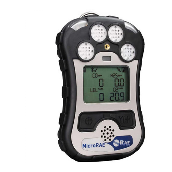
MicroRAE User’s Guide 2. General Information The MicroRAE gas monitor combines continuous monitoring capabilities for toxic and combustible gases with Man Down Alarm functionality, BLE (Bluetooth Low Energy), and optional GPS and either WiFi or Mesh Radio wireless connectivity in a compact, portable instrument. -
Page 11: User Interface
MicroRAE User’s Guide 3. User Interface The MicroRAE’s user interface consists of the display, LEDs, an alarm buzzer, and two keys. 3.1. Display Overview The LCD display provides visual feedback that includes the sensor types, readings, battery condition, and other functions. - Page 12 MicroRAE User’s Guide Icon Function Network joined, signal low RSSI (20% to 49%) Network joined, signal medium RSSI (50% to 69%) Network joined, signal good RSSI (70% to 100%) No radio icon: The instrument is not equipped with a radio module.
-
Page 13: Keys & Interface
Press a key when the backlighting is off to turn it on. 3.2. Screen Display For Various Numbers Of Active Sensors The MicroRAE can accommodate from one to four sensors. When one or more sensors is either not installed or turned off, the display only shows the installed, active sensors:... -
Page 14: Menus
* If the MicroRAE is WiFi equipped: WiFi-equipped instruments can receive up to five messages. If a message has been received by the MicroRAE, the number of messages is displayed (1 MSG, etc.). The display shows the message sequentially, cycling through the message each half-second. -
Page 15: Glance Mode
Press [Y/+] to clear the alarm. The alarm stops and the display returns to the main reading screen. 3.6. Confidence LED You can use ProRAE Studio II to program the MicroRAE to continually provide an LED blink every 3 seconds so that you can tell without looking closely that the instrument is working. -
Page 16: Mesh Wireless Control And Submenus
If Roaming is not turned on, then you must set a PAN ID in order to communicate with a Mesh Network. Note: These are only present if the MicroRAE is equipped with a Mesh Network wireless module. -
Page 17: Battery Charging
LED glows red. The LED glows green when the battery is fully charged. Note: For mobile charging, only use Automotive Charging Adapter (P/N 003-3004-000) from RAE Systems. To remove the MicroRAE from the Travel Charger, squeeze the latches on the sides of the Travel Charger and pull it away from the instrument. - Page 18 5.1.1 Charging With The Multi Charger Press the MicroRAE into any of the Multi Charger’s cradles. It should be held firmly in place. If the power is connected to the Multi Charger, the LED indicator on the cradle should glow. When power is applied and the MicroRAE’s battery is charging, the LED glows red.
- Page 19 MicroRAE User’s Guide Remove the instrument from the cradle by tilting the release on the rear of the charging cradle away from the instrument and lifting the MicroRAE.
-
Page 20: External Filter
6. External Filter The External Filter (M03-3009-000) is designed to prevent debris from entering the MicroRAE in dirty or dusty environments. Align the filter over the sensor openings and tighten the Philips... -
Page 21: Turning The Microrae On And Off
With the instrument turned off, press and hold the [MODE] key until the audible alarm stops, and then release. When starting up, the MicroRAE turns the backlight on and off, beeps once, blinks once, and vibrates once. A RAE Systems logo should appear first. During a normal startup, this is followed by a progression of screens that tell you the MicroRAE’s current settings. -
Page 22: Testing Alarm Indicators
“On”). This can be done in ProRAE Studio II. With the MicroRAE turned off, press and hold [Y/+] to enter Glance Mode. The feature is latched, meaning that it runs even after you release the [Y/+] key. If you see the message “GLANCE DISABLED,”... -
Page 23: Exit Glance Mode
Super Alarm (gas and Man Down) with four beeps/flashes per second. When the Man Down feature is on and there is no gas alarm, the MicroRAE senses that it is motionless for the amount of time set in the “Motionless Time” parameter via ProRAE Studio II. If the instrument is not moved during that time, then a pre-alarm is activated to alert the user, and shows the “OK?”... - Page 24 When the Man Down alarm is activated, the buzzer sounds and LEDs flash continuously, and a countdown begins. • If the MicroRAE’s user presses [Y/+] for “Yes” in response to the “OK?” question on the screen before the countdown reaches zero, the Man Down alarm stops and the main reading screen is displayed.
- Page 25 MicroRAE User’s Guide 7.8. Bump Status If any sensor requires a bump test, then “Bump Overdue” icon is shown by the sensor name in the display: A bump test is required if the defined period of time between bump tests has been exceeded. This...
-
Page 26: Modes Of Operation
Note: Some settings are only visible and can only be changed in ProRAE Studio II. This requires connecting the instrument to a computer running ProRAE Studio II and having administrative privileges. For a list of which parameters can be set in Programming Mode on the MicroRAE, in ProRAE Studio II, or both 9.1. -
Page 27: Enter Programming In Advanced Mode
MicroRAE User’s Guide Once you enter Programming Mode, the Calibration screen is shown. Press [MODE] to step through the programming screens. 9.2. Enter Programming In Advanced Mode To enter Programming Mode, press and hold [MODE] and [Y/+] until you see the Calibration screen. -
Page 28: Calibration
MicroRAE User’s Guide 9.3.1. Calibration Use this menu to perform zero or span calibration for one or more sensors, and change the gas concentration value assumed to be used in span calibration, as well as zero calibration and calibration reference gas. Refer to “Calibration And Testing” on page 39 for guidance on setting up the instrument for calibration. - Page 29 9.3.1.4. Multi Bump Depending on the configuration of your MicroRAE and the span gas you have, you can perform a bump test simultaneously on multiple sensors. The selected sensors and their values are shown on the screen. With calibration gas connected to the instrument, start a multiple bump test by pressing [Y/+].
-
Page 30: Sensor On/Off
3. Press [MODE] to save your choice and advance to “Set Site ID”. 9.3.4.2. Set User ID If your MicroRAE is to be used by a specific user, it can have a uniquely named User ID (a name or numbers or combination) to help identify it in ProRAE Guardian monitoring software. The User ID must be eight alphanumeric characters. -
Page 31: Set Site Id
9.3.4.3. Set Site ID If your MicroRAE is to be used at a specific site, it can have a uniquely named Site ID (a name or numbers or combination) to help identify it in ProRAE Guardian monitoring software. The Site ID must be eight characters in length, with the first four characters alphanumeric (letters and numerals) and the last four must be numerals. -
Page 32: Radio On/Off
This is only available if your MicroRAE is configured with WiFi or Mesh Radio. You can tell the MicroRAE to automatically join a network. The PAN ID and Channel are shown for reference (if either is incorrect, you can change it, as described above). Press [Y/+] to join or [MODE] to advance to “Interval”... -
Page 33: Factory Reset
MicroRAE User’s Guide While it is searching for a network to join, the display shows this message: If it is unsuccessful, the display shows this message: Check your other settings, as well as those of the network you are trying to join. -
Page 34: Parameters Accessed Through Prorae Studio Ii
ProRAE Studio II. 9.4.1.1. Alarm Mode You can program the MicroRAE so that there are two ways to shut off an alarm: When the alarm condition is no longer present, the alarm stops and resets itself. Auto Reset... - Page 35 9.4.1.8. Zero At Start If your MicroRAE has been configured to perform a zero (fresh air) calibration upon startup, called Zero At Start, then the startup routine is interrupted so that you can perform a fresh air calibration. Choices are On or Off.
-
Page 36: Policy Enforcement
MicroRAE screen: If Policy Enforcement is enabled, then after startup the MicroRAE displays a screen that informs the user that the instrument requires either a bump test or a calibration. If both... - Page 37 Make sure the AC adapter is connected and that a USB cable is connected between the Travel Charger and a computer running ProRAE Studio II. 1. Turn on the MicroRAE. Allow the system to start up and go through its startup routine.
- Page 38 14. A confirmation screen is shown. Click “Yes” to perform the upload, or “No” to abort. Uploading takes a few seconds, and this progress bar is shown. You can abort the upload by clicking “Cancel.” 15. Exit ProRAE Studio II. 16. Press [MODE] on the MicroRAE to apply settings and exit Communication Mode.
-
Page 39: Calibration And Testing
• The MicroRAE multi-gas detector must be calibrated if it does not pass a bump test, or at least once every 180 days, depending on use and sensor exposure to poisons and contaminants. -
Page 40: Bump (Functional) Testing (Single Bump Or Multi Bump)
If it has not warmed up, you see three dashes (“--”) next to it. 2. Install the calibration adapter on the MicroRAE by setting it on over the sensors and turning the knob until it is snug against the surface of the instrument. -
Page 41: Zero Calibration
This operation sets the zero point of the sensor calibration curve for clean air. It should be performed before other calibrations. Note: If you use a zero air cylinder, you must use the MicroRAE Calibration Adapter. Using a calibration adapter is not necessary for calibration in fresh air. -
Page 42: Span Calibration
Calibration Adapter must be used for supplying calibration gas to all sensors at one time: 1. Align the Calibration Adapter’s main body with the indented area around the MicroRAE’s gas inlets. 2. Turn the knob clockwise to secure the Calibration Adapter to the instrument. - Page 43 MicroRAE User’s Guide 6. Press [Y/+] to start calibrating. You can abort the calibration at any time during the countdown by pressing [MODE]. After a timer countdown, the span calibration is done. The LCD will display whether the calibration was successful and the reading for that calibration gas.
-
Page 44: Datalog Transfer, Monitor Configuration, And Firmware Upgrades Via Computer
Datalogs can be downloaded from the MicroRAE to a computer, and firmware updates can be uploaded to the MicroRAE via the USB port on the Travel Charger. Use the included Mini B USB (5-pin)-to-USB cable to connect the Travel Charger to a computer running ProRAE Studio II (version 1.10.0 or higher). -
Page 45: Maintenance
13.1. Removing Sensors WARNING! Do not replace sensors in hazardous locations. All sensors are located inside the sensor compartment in the upper half of the MicroRAE. To access the sensors: 1. Turn off the instrument. 2. Remove the four screws in the back of the instrument. - Page 46 MicroRAE User’s Guide The LEL sensor is square and has four pins that insert into four plated holes in the PC board. When removing or installing an LEL sensor, lift it straight out and be careful not to bend the pins.
- Page 47 13.4. Reassembling The MicroRAE When you reassemble the MicroRAE, inspect for any damage and make sure the sealing rib is in place and that you use new O-rings for the four screws. (Screws and O-rings, package of 10, P/N: M03-3010-000.) Important! If the housing is damaged, it should be replaced.
-
Page 48: Alarms Overview
Low, High, TWA and STEL alarm. If the concentration exceeds any of the preset limits, the alarms are activated immediately to warn both the MicroRAE user and a remote safety officer (if wireless is enabled) of the alarm condition. - Page 49 Notes • “Negative” means that the reading is below zero. • “Network Lost” means that the MicroRAE has lost wireless connectivity with its network. • “Network Joined” means that the MicroRAE has joined a wireless network. • “CAL” includes Span calibration failure, Zero/fresh air calibration failure.
- Page 50 [Y/+]. If any alarm does not respond, connect the MicroRAE to a PC running ProRAE Studio II and check the alarm settings to make sure all alarms are enabled. If any alarms are enabled but not functional, the instrument should not be used.
-
Page 51: Troubleshooting
Most of these screens are useful only to service technicians. Many allow access for changing settings. The MicroRAE’s Diagnostic Mode can only be accessed at startup time. In Diagnostic Mode, MicroRAE displays readings in raw counts instead of units such as parts per million (ppm) or other units of measure. 16.1. - Page 52 MicroRAE User’s Guide 16.3. Navigating Diagnostic Mode Step through Diagnostic Mode by pressing [MODE]. The first screen you see is information about the product, including the serial number, firmware version, etc. Exit Diagnostic Mode at any time by shutting the instrument off (hold [MODE] for the 5-second countdown).
-
Page 53: Editing Features
MicroRAE User’s Guide 17. Editing Features Some features can be turned on or off or edited directly on the MicroRAE, some can only be accessed through ProRAE Studio II, and some can be accessed and changed through both. The table below shows where features can be accessed. - Page 54 MicroRAE User’s Guide Editing Features, continued Feature MicroRAE ProRAE Studio II GPS On/Off GPS Recover Mode Period BLE On/Off WiFi On/Off Set Access Point SSID Set Access Point Password DHCP Enable ...
-
Page 55: Specifications
Approvals EchoView Host & MicroRAE: Line of sight >200m (650 ft), receiving data >80% Wireless Range ProRAE Guardian & Mesh Reader & MicroRAE: Line of sight >200m (650 ft), receiving data (Typical) >80% ProRAE Guardian & RAELink3 & MicroRAE: Line of sight >100m (330 ft), receiving data >80%... - Page 56 LEL Range, Resolution & Response Time Range 0 to 100% LEL Resolution Response Time: < 30 sec. Caution: • Refer to RAE Systems Technical Note TN-114 for LEL sensor cross-sensitivities. • Refer to RAE Systems Technical Note TN-144 for LEL sensor poisoning.
- Page 57 MicroRAE User’s Guide Year Of Manufacture To identify the year and month of manufacture, refer to the two digit marking placed adjacent to the serial number on the instrument label according to the following table: Year First digit Month Second digit...
- Page 58 MicroRAE User’s Guide Sensor Parameters Edit Range Parameter Unit Minimum Maximum Default CO Span CO Range 1000 CO Low 1000 CO High 1000 CO STEL 1000 CO TWA 1000 S Span S Range S Low S High S STEL S TWA...
-
Page 59: Controlled Part Of The Manual For
IEC standard. The maximum voltage from the charger shall not exceed 6.0 Vdc. Likewise, any data download device connected to the PGM-2600 shall also be approved SELV or Class 2 equipment. Use of non-RAE Systems components will void the warranty and can compromise the safe performance of this product. - Page 60 MicroRAE User’s Guide PGM2600 Marking The PGM-2600 is certified according to the IECEx scheme, ATEX and CSA for US and Canada as protected by intrinsic safety. The PGM-2600 is certified according to the IECEx scheme, ATEX and CSA for US and Canada under the intrinsic safety method of protection.
- Page 61 MicroRAE User’s Guide Operation Area and Conditions Hazardous Areas classified by Zones PGM-2600 are intended to be used in hazardous areas classified zone 1 or zone 2 within the temperature range of -20ºC to +60ºC, where gases of explosion groups IIA, IIB or IIC and T4 may be present, and in underground mines endangered by firedamp.
- Page 62 MicroRAE User’s Guide Year of manufacture To identify the year and month of manufacture, refer to the two digit marking placed adjacent to the serial number on the instrument label according to the following table: Year First digit Month Second digit...
-
Page 63: Technical Support
MicroRAE User’s Guide 20. Technical Support To contact RAE Systems Technical Support: Monday through Friday, 7:00AM to 5:00PM Pacific (US) Time Phone (toll-free): +1 877-723-2878 Phone: +1 408-952-8200 Fax: +1 408-952-8480 Email: RAE-tech@honeywell.com 21. RAE Systems Contacts RAE Systems by Honeywell World Headquarters 3775 N. - Page 64 MicroRAE User’s Guide CORPORATE HEADQUARTERS RAE Systems by Honeywell 3775 North First Street San Jose, CA 95134 USA Phone: 408.952.8200 Fax: 408.952.8480 RAE-tech@honeywell.com WORLDWIDE SALES OFFICES USA/Canada 1.877.723.2878 Europe +800.333.222.44/+41.44.943.4380 Middle East +971.4.450.5852 China +86.10.5885.8788-3000 Asia P acific +852.2669.0828 Rev. A...
Need help?
Do you have a question about the microrae and is the answer not in the manual?
Questions and answers